SF6 Circuit Breaker Maintenance: Checklist, Intervals & Best Practices
Published: Author: Lisa
Most SF6 circuit breakers do not fail because they were badly made. They fail because nobody looked at them for six years, and the first symptom was a lockout during a storm. A working SF6 circuit breaker maintenance programme is not a list of tasks borrowed from a manual — it is a schedule built around the three things that actually degrade in service: gas tightness, mechanism condition, and contact wear.
This guide sets out a practical maintenance regime for outdoor high-voltage SF6 breakers in the 40.5 kV to 252 kV range, the kind used in distribution and industrial substations from the high voltage SF6 circuit breakers range. It covers what to check, how often, what the readings mean, and where a maintenance plan usually goes wrong. Manufacturer instructions always override generic intervals — treat what follows as the framework you adapt, not a substitute for the OEM manual.
What Maintenance Is Actually Protecting Against
Three degradation mechanisms account for the overwhelming majority of SF6 breaker failures in service. Each one has a different timescale, which is why a single “annual service” cannot address all three equally.
Gas loss and moisture ingress — slow, measured in fractions of a percent per year. A seal that leaks 0.3% per year is within specification; a seal that starts leaking 3% per year will reach lockout in a few years without anyone noticing unless density trends are recorded.
Mechanism degradation — lubrication drying out, damper wear, spring fatigue, auxiliary contact erosion, coil resistance drift. This is what turns a breaker that opens in 40 ms into one that opens in 90 ms, or does not open at all.
Contact and nozzle wear — cumulative, driven by fault interruptions rather than by time. A breaker that has cleared twenty 40 kA faults is not in the same condition as one that has never fault-tripped, even if both are ten years old.
Any maintenance plan that only counts calendar years misses the third mechanism entirely, and any plan that only counts operations misses the first two. A defensible programme uses all three inputs.
The Maintenance Interval Ladder
Intervals in this table reflect common utility and industrial practice. They assume a breaker in a reasonably clean outdoor environment; coastal, desert, heavily polluted or very humid sites should compress every interval.
Stage
Typical timing
Main focus
Commissioning checks
Before energisation
Gas purity and dew point, density relay settings, wiring, interlock tests, timing and resistance baseline
Routine inspection
Every 6 to 12 months
Visual condition, gas density reading, leak survey, cabinet heating, counter and alarm log
Gas top-up, seal replacement, contact wear assessment, mechanism overhaul
Major overhaul or replacement
12 to 20 years, or at rated operations
Interrupter inspection, seal replacement, full mechanism refurbishment
Two adjustments matter more than the table itself. First, breakers that trip frequently on faults should move to a shorter preventive interval regardless of age — the accumulated breaking duty is the real clock. Second, any breaker that has been in storage or de-energised for more than a year needs the commissioning checks repeated before it is put back into service, because seals and lubrication do not improve with idleness.
Intervals shift shorter as pollution, humidity and fault frequency rise.
Routine Inspection Checklist
Routine inspection is a visual and sensory pass, done with the breaker in service. It should take under an hour per breaker and it catches the majority of developing faults early. Do it with a written checklist and record the values, not just a tick.
Gas density gauge reading — record the value and the ambient temperature at the time. A single reading tells you little; a trend tells you everything.
Oil or grease traces below the mechanism box, on the base frame or on the foundation — usually the first visible sign of a seal or damper problem.
Porcelain and composite condition — chips, cracks, tracking marks, heavy pollution deposits, bird nests or vegetation contact.
Rust and paint damage on the tank, frame and terminal pads, especially at the base where water collects.
Terminal connections — discolouration, heat marks, loose bolts, and the condition of flexible braids or expansion links.
Mechanism cabinet — door seals, heater operation, condensation inside, insect or rodent entry, desiccant condition.
Counter readings — total operations and fault-trip counter, if fitted. Record both; the difference is the number of fault interruptions.
Alarm and event log — any low-density alarm, motor protection trip, or heater failure since the last visit.
Labels and safety signage — legible, present, and matching the current single-line diagram.
Infrared thermography belongs on this list as well, but as a separate exercise with the breaker under load. Comparing phase-to-phase temperature on the terminals and bushings will find loose connections long before they fail.
Gas System Checks
The gas system is where most maintenance decisions are actually made, and where most maintenance errors happen.
Density and dew point readings are only useful when recorded and trended.
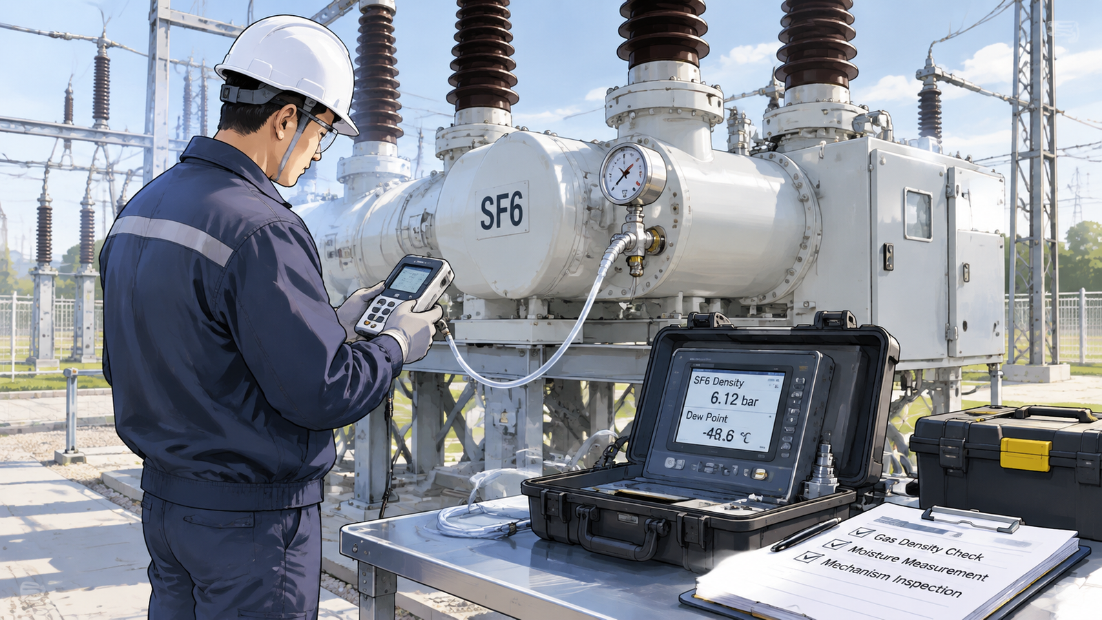
Read density, not pressure. SF6 pressure changes with ambient temperature following a predictable curve, so a gauge reading of 0.55 MPa at 15 °C and 0.62 MPa at 35 °C may both represent the same density. Every SF6 breaker is fitted with a temperature-compensated density relay for exactly this reason, and the relay’s two stages — alarm and lockout — are set in density, not pressure. If someone tops up a breaker to “the right pressure” on a cold morning, they will overfill it and stress the relief device. Top up to the density curve in the manual, using the temperature correction table.
Track the leak rate, not the leak. A single top-up is an event; a leak rate is a diagnosis. Record every top-up with date, quantity and the density before and after. Closed pressure systems are typically allowed around 0.5% per year of the compartment’s filling quantity, and sealed-for-life designs around 0.1% per year. A breaker that needs topping up twice in three years is leaking well beyond specification and needs a seal investigation, not another cylinder.
Check moisture on a schedule, not on suspicion. Moisture enters through seals and through gas handling itself. Dew point measurement at commissioning and then at every preventive maintenance visit is enough; anything approaching the limit in the OEM manual triggers a dry-out or gas replacement. Moisture limits are voltage-class dependent and are covered in detail in the SF6 gas quality guide.
Use a proper leak survey. Annual surveys with a portable detector around flanges, density relay connections, gauge roots, the burst disc and the operating rod seals will localise a leak before it becomes an outage. Where the detector is inconclusive, bagging the suspect joint and measuring concentration build-up gives a quantitative answer.
Never repeatedly top up a leaking compartment. This is the single most common bad practice in SF6 maintenance. Each top-up adds moisture and handling risk, masks the trend, and eventually delivers a breaker that reaches lockout mid-operation. If a compartment will not hold density, find the leak or replace the compartment.
Gas pressure ratings are part of the design, not a maintenance variable. Units such as the 40.5 kV breaker rated at 0.5 MPa gas pressure are engineered around a specific density; deviating from it in either direction changes both the dielectric margin and the interruption capability.
Mechanism Maintenance
The operating mechanism is the highest-risk subsystem in any SF6 breaker, and it is the one most often left alone because it is “sealed” or “maintenance-free”. Nothing mechanical is maintenance-free over twenty years.
Spring mechanism checks. Verify the recharge time against the manual — a spring that takes noticeably longer to recharge points to a tired motor, a dry bearing or a weakening spring. Measure motor current; a rising trend indicates mechanical resistance. Check the close and open coil resistances and compare against the commissioning baseline, and confirm anti-pumping operates by holding the close command on.
Lubrication. Apply only the lubricant specified by the manufacturer, at the points specified. The wrong grease on a mechanism is worse than no grease, because it can harden, migrate into contact areas, or attack seals. Re-lubrication intervals are typically tied to the preventive maintenance cycle, not to the inspection cycle.
Dampers and buffers. End-of-travel dampers absorb energy on every operation. Worn dampers change the closing characteristic and increase shock loading on the interrupter, which shows up later as cracked nozzles or loosened contacts. Check for oil seepage and for a change in the sound of the closing operation.
Auxiliary contacts and wiring. Auxiliary contacts carry the interlock logic and the breaker-failure signals. Clean, inspect for erosion, and verify changeover timing. Loose terminal screws inside the cabinet are a recurring cause of intermittent “breaker status unknown” alarms that send maintenance teams chasing the wrong fault.
Mechanical endurance baseline. The design endurance class tells you how many operations the mechanism is built for. A breaker rated for 3000 operations of mechanical life at 40.5 kV is expected to reach that count with routine lubrication, not with an overhaul at 500. Track operations against the class rating — it is the only honest way to judge whether a mechanism is “old”.
How spring, pneumatic and hydraulic mechanisms differ in maintenance burden is covered in SF6 breaker operating mechanisms; spring designs dominate new installations precisely because they need the least routine attention.
Contact and Interrupter Wear
Contact wear is the one maintenance item that cannot be judged by looking at the outside of the breaker, and the one most often skipped because it requires an outage.
Measure static contact resistance. Inject a DC current — typically 100 A to 200 A — across each pole and record the micro-ohm value. Compare phases against each other and against the commissioning baseline. A phase that has drifted 20% above its siblings is telling you something, even if the absolute value is still inside the limit. Rising resistance means contact erosion, loose joints or surface film, and it also means heat.
Assess accumulated breaking duty. Electrical endurance is not a count of operations; it is a weighted sum in which each interruption contributes in proportion to a power of the current it interrupted, typically between 1.8 and 2. The practical consequence is that one 40 kA fault interruption consumes as much contact life as dozens of load-current operations. Record every fault trip with its current, and sum the duty against the interrupter’s rated electrical endurance.
Check travel and penetration where the design allows. On breakers with accessible contact assemblies, measure contact travel, overtravel and penetration against the manual. On sealed-for-life interrupters, this is replaced by resistance trending and by the accumulated duty calculation.
Do not open a sealed interrupter to “have a look”. Breaking the gas seal on a sealed-for-life unit converts a maintenance task into a workshop overhaul and usually voids the warranty. If the resistance trend and duty sum both say the interrupter is worn, replace the pole unit rather than inspecting it.
Electrical and Insulation Checks
These checks are cheap, and they catch the failures that would otherwise appear as flashovers.
Insulation resistance on each pole to earth and across the open gap, at the voltage specified in the manual. Trend the values; a single pass is nearly meaningless.
Power-frequency withstand on the open gap during major overhauls, where test equipment is available. This is the check that proves the interrupter still has dielectric margin.
Partial discharge or UV imaging on porcelain and composite insulators at polluted sites, to find tracking before it becomes a flashover.
Infrared survey under load, on terminals, bushings and cable connections.
Protection trip test from the relay through the trip coil, to prove the whole chain and not just the breaker. A breaker that passes a local trip test but cannot be tripped from the relay is not maintained — it is untested.
The full set of type, routine and commissioning tests, and how they differ from in-service maintenance testing, is set out in SF6 circuit breaker testing. The acceptance criteria those tests are judged against come from the IEC 62271-100 and IEEE C37 standards, which is also where the endurance classes that define “worn out” are written down.
Records and Condition-Based Triggers
A maintenance programme is only as good as its records. Without a baseline and a trend, every reading is an opinion. The minimum record set per breaker is: commissioning values for gas density, dew point, contact resistance, timing and coil resistance; every top-up with quantity and date; every fault trip with current; and every alarm with its timestamp.
Observation
Likely cause
Action
Density falling faster than 0.5% per year
Seal degradation, gauge root leak, burst disc seepage
Leak survey, then seal replacement at the next outage
Dew point rising between visits
Moisture ingress through seals or during top-up
Dry-out or gas replacement; check handling procedure
Contact resistance rising on one phase
Contact erosion, loose terminal, surface film
Re-torque, then schedule interrupter assessment
Recharge time increasing
Motor wear, dry bearings, spring fatigue
Lubricate and measure motor current; replace motor if trending up
Operating times drifting
Damper wear, linkage wear, low gas density
Compare against baseline; investigate before the next fault
Condensation inside the cabinet
Heater failure, door seal failure
Replace heater and seal; dry the cabinet before energising
Frequent low-density alarms
Genuine leak or a failing density relay
Cross-check with a calibrated gauge before replacing gas
Each row in that table is a trigger, not a fault. The point of condition-based maintenance is to act at the trigger stage, when the intervention is a seal, a lubricant or a re-torque, rather than at the failure stage, when it is a pole replacement and an unplanned outage.
Maintenance Mistakes Worth Avoiding
Treating the annual inspection as the whole programme. A visual pass with no measurements produces no trend, and no trend means no early warning.
Topping up instead of diagnosing. Repeated top-ups hide leak rates and add moisture. They are the most expensive form of “fixing” an SF6 breaker.
Ignoring the fault-trip counter. Time-based maintenance on a breaker that has cleared fifteen faults is maintenance aimed at the wrong failure mode.
Testing the breaker but not the trip path. The most common reason a maintained breaker fails to trip is not the breaker — it is a relay output, a wiring termination or a DC supply that was never in the test.
Using the wrong lubricant or the wrong grease quantity. Both cause mechanism problems that take years to trace.
Opening sealed interrupters for inspection. It converts a healthy unit into a workshop job and often into a warranty dispute.
Building a Programme That Survives Contact With Reality
The practical recipe is short. Set intervals from the manufacturer’s manual, then compress them for pollution, humidity and fault frequency. Record four numbers at commissioning — density, dew point, contact resistance and operating time — because everything later is a comparison against them. Survey for leaks annually. Test the trip path from the relay, not just from the local cabinet. And treat every fault trip as a data point that consumes interrupter life.
For industrial substations where the breaker protects a production line rather than a transmission corridor, the cost of an unplanned trip usually dwarfs the cost of the switchgear itself, which is why units designed for industrial power grid protection at 126 kV are specified with accessible mechanism cabinets and standard gas interfaces — the maintenance access is part of the product, not an afterthought. Where the load is heavier and the breaker is worked harder, a 40 kA class 126 kV unit gives more interrupter margin for the same maintenance effort.
If you are writing a maintenance specification for a new installation, start from the selection sequence — the ratings you choose there determine how much maintenance the breaker will need over its life.
Frequently Asked Questions
How often should an SF6 circuit breaker be serviced?
Routine visual inspection every 6 to 12 months, preventive maintenance every 3 to 6 years, and a major overhaul at 12 to 20 years or when the rated operation count is reached. Sites with heavy pollution, high humidity or frequent fault tripping should use the shorter end of every range.
Can SF6 breakers be maintained while energised?
Only visual inspection, gas density reading, infrared survey and leak detection can be done with the breaker in service. Anything involving the mechanism, the gas compartment, the secondary wiring or the contacts requires the breaker to be isolated, and gas work requires the compartment to be de-energised and earthed.
What is a normal SF6 leak rate?
Closed pressure systems are typically permitted around 0.5% per year of filling quantity, and sealed-for-life designs around 0.1% per year. Anything above the specification in the manual is a leak to be found, not a top-up to be scheduled.
How do I know when the interrupter is worn out?
Two indicators: a contact resistance trend that has drifted significantly above the commissioning baseline, and an accumulated breaking duty that has reached the interrupter’s rated electrical endurance. The duty is calculated by summing each fault interruption weighted by a power of the current, not by counting operations.
Does topping up the gas extend breaker life?
No. Topping up restores density but does nothing about the leak, and each top-up introduces moisture and handling risk. It is a temporary measure to keep a breaker in service until the leak can be repaired, not a maintenance strategy.
Why do breakers fail shortly after maintenance?
Usually because something was disturbed and not restored: a wiring termination, an auxiliary contact, a heater, a density relay connection, or a mechanism left with the wrong lubricant. Post-maintenance testing from the relay through the trip coil, plus a full interlock verification, catches most of these before energisation.
Why a breaker rated 40 kA may still restrike on 50 A: the four capacitive duties, preferred current values by voltage class, C1 vs C2 tests and what to check.