Live Tank vs Dead Tank SF6 Circuit Breakers: Which Configuration Fits Your Grid?
A bay-level comparison of live tank and dead tank SF6 breakers: CT integration, footprint, seismic behaviour, maintenance and where each wins.
Read More
A circuit breaker rated 40 kA can interrupt a fault current eight hundred times larger than the 50 A charging current of an unloaded cable. That same breaker may still restrike on the 50 A. This is the counter-intuitive fact at the centre of capacitive current switching, and it is why a short-circuit rating tells you almost nothing about whether a breaker can be trusted on cables, capacitor banks and unloaded lines.
The current is small. The recovery voltage is not. When a breaker clears a capacitive circuit it traps charge on the load side at peak voltage while the source swings to the opposite peak half a cycle later, so the contact gap must withstand roughly twice the system peak at the very moment it is shortest. If the gap breaks down, current flows again, the trapped charge is topped up, and the voltage escalates with every event. The C1 and C2 classes exist to quantify how well a design resists that, and capacitive duty is specified separately from short-circuit duty in every serious SF6 circuit breaker datasheet for exactly this reason.
This guide covers the four capacitive duties that get rated, the preferred current values by voltage class, how the C1 and C2 test regimes differ, what a restrike costs, and what to demand in writing when you specify for capacitor bank or cable duty.
Three things change when the current falls from tens of kiloamps to tens of amps. None of them is about carrying current, and all of them are about the two or three milliseconds around current zero.
Most modern SF6 interrupters are self-blast or hybrid designs. The arc heats gas in an expansion volume, and the pressure built during the arc is what blasts across the gap at current zero and rebuilds dielectric strength. The mechanism scales with fault level: 40 kA of arc energy produces an enormous pressure rise in a fraction of a millisecond.
At 50 A there is almost no arc energy to harvest. The blast has to come from a mechanical puffer volume driven by the mechanism, or from a design that deliberately provides cold gas flow at low current. A chamber optimised purely for thermal self-blast can therefore be excellent at 40 kA and only adequate at 50 A. That is why serious manufacturers describe their interrupters as covering the whole current range rather than a single point on it, and why the difference between puffer and self-blast interrupter designs matters more here than in fault clearing.
In a capacitive circuit the current leads the voltage by a quarter cycle, so at the instant of current zero the load-side voltage is at its peak. If the contacts part close to that zero, the arc lasts only a moment and the gap at the following current zero is a few millimetres wide — and that narrow gap must hold off twice the peak voltage a quarter cycle later.
Short-circuit interruption is forgiving in comparison: the arc burns long enough for the contacts to travel a substantial distance before current zero arrives. Capacitive test duties therefore distribute operations across both polarities and across short and long arcing times. The short-arcing cases are the hard ones, and a report that quotes a restrike-free result without stating the arcing-time distribution is not telling you much.
Small inductive currents — transformer magnetising current, shunt reactor current — are chopped before their natural zero, and the stored magnetic energy produces an overvoltage. Capacitive duty works the other way round: the current is interrupted cleanly at zero and the problem is the charge left behind. Both involve a few tens of amps and both get called “small current switching”, which is why the two are so often confused in specifications. They need different ratings and different tests.
IEC 62271-100 does not define a single “capacitive switching current”. It defines four separate ratings, and a breaker may be assigned any combination of them. A datasheet that lists only one number is either incomplete or hiding a limitation.
| Rated quantity | What it covers | Typical order of magnitude |
|---|---|---|
| Rated line-charging breaking current, Il | Dropping an unloaded overhead line; capacitance is distributed along the conductors | Tens of amps at 72.5 kV, rising to several hundred amps at 420 kV |
| Rated cable-charging breaking current, Ic | Dropping an unloaded cable circuit; far higher capacitance per kilometre than a line | Tens to a few hundred amps, by voltage class and cable construction |
| Rated single capacitor bank breaking current, Isb | Isolating one shunt bank with no other bank in parallel nearby | Hundreds of amps |
| Rated back-to-back capacitor bank breaking current, Ibb | Isolating one bank while another is already energised on the same busbar | Hundreds of amps, plus a separate inrush making rating |
Back-to-back duty adds a rating that has nothing to do with breaking. Energising a bank next to an already-charged bank drives a very high-frequency current through the closing contacts, and the standard’s preferred values are 20 kA peak at around 4,250 Hz. At that frequency the current is limited mainly by the loop inductance between the banks, which is why back-to-back installations almost always include a series reactor. Without one, the inrush can exceed what the contacts can make without welding or heavy erosion.
The practical consequence: a breaker can break 400 A of capacitor current perfectly well and still be wrong for a back-to-back installation, because making is a separate qualification.
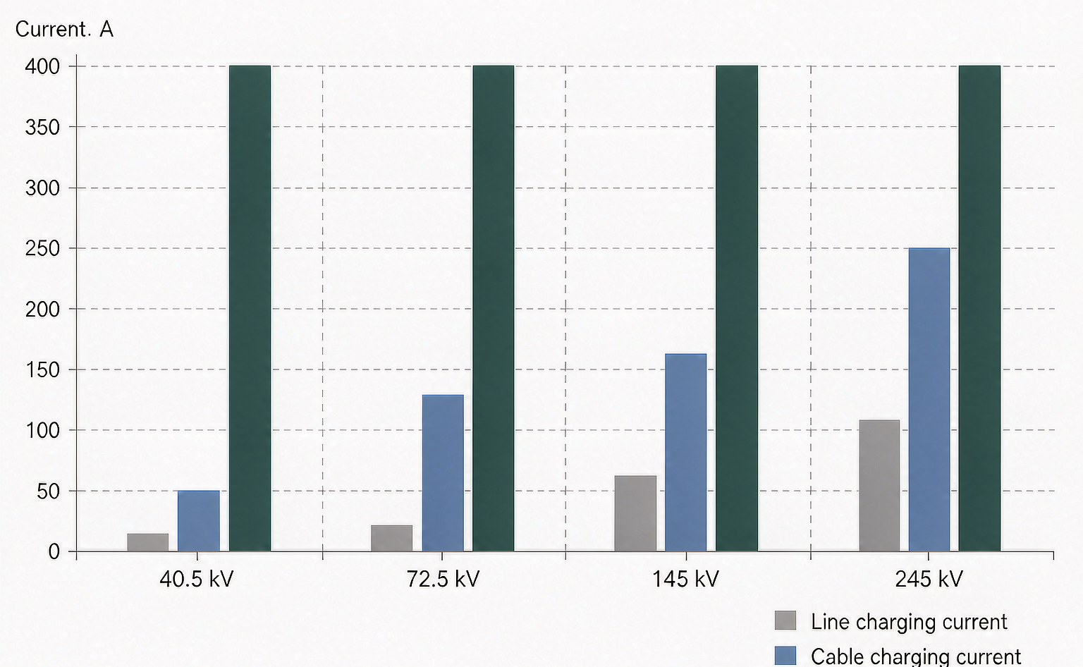
The standard publishes preferred values so that a 145 kV breaker from one supplier and a 145 kV breaker from another can be compared at all. These are the preferred values from IEC 62271-100:2021 with Amendment 1:2024 for the classes that matter in distribution and sub-transmission work.
| Rated voltage Ur (kV) | Line charging Il (A) | Cable charging Ic (A) | Single bank Isb (A) | Back-to-back Ibb (A) | Inrush Ibi (kA peak) |
|---|---|---|---|---|---|
| 12 | 10 | 25 | 400 | 400 | 20 |
| 24 | 10 | 31.5 | 400 | 400 | 20 |
| 36 | 10 | 50 | 400 | 400 | 20 |
| 40.5 | 10 | 50 | 400 | 400 | 20 |
| 72.5 | 10 | 125 | 400 | 400 | 20 |
| 123 | 31.5 | 140 | 400 | 400 | 20 |
| 145 | 50 | 160 | 400 | 400 | 20 |
| 245 | 125 | 250 | 400 | 400 | 20 |
| 420 | 400 | 400 | 400 | 400 | 20 |
These are preferred values chosen for standardisation, not physical limits: a manufacturer may offer more, and a project may legitimately need more. The line-charging figure scales hardest with voltage. At 40.5 kV, 10 A covers tens of kilometres of overhead line; at 420 kV, 400 A corresponds to roughly four hundred kilometres, and the interruption is no longer a small-current problem in any meaningful sense. At medium voltage the line-charging rating is rarely the binding one, because distribution feeders are cables — the 50 A cable-charging rating at 40.5 kV is what governs.
The class is a statement about restrike probability, demonstrated by type test. It says nothing about current magnitude and is not interchangeable with the ratings above: a breaker needs both the current rating and the class.
| Class C1 | Class C2 | |
|---|---|---|
| Restrike probability | Low | Very low |
| Preconditioning | None | Terminal fault T60 — three close–open operations at 60% of rated short-circuit current |
| Full-current series | 24 close–open operations at 100% | Around 128 close–open operations at 100% across the three duties |
| Restrikes permitted | Up to one during duties 1 and 2, with a repeat rule if a second occurs | None. One restrike restarts the series; a second fails the test |
| Where it is used | Infrequent switching of lines and cables | Capacitor banks and any circuit switched frequently |
Test duty 1 is the arcing-time-sensitive part: 24 opening operations at 10% to 40% of rated capacitive current, distributed across both polarities and across deliberately short and long arcing times. The current is easy. The point is to arrive at current zero with a short gap and a long arcing time — the worst combination for dielectric recovery.
Test duty 2 repeats the exercise at 100% as close–open operations, so the making prestrike and the break that follows are both exercised. For capacitor bank duty the full-current series is much longer than for line or cable duty, because bank switching happens often and a restrike on a bank is more damaging.
Operations run at rated voltage measured at the terminals immediately before opening, with the recovery voltage shaped for the capacitive case. That recovery voltage is the whole test: it is what the gap must survive, which is why arcing-time distribution matters more than current level.
The T60 preconditioning is not administrative. Three close–open operations at 60% of rated short-circuit current leave the interrupter, nozzle and contacts in the state they would be in after a period of fault clearing: eroded nozzle throat, roughened contact surfaces, decomposition byproducts in the gas. A C2 claim is a claim about performance in that condition, not about a factory-fresh chamber.
This is also why C2 is normally paired with an extended mechanical class. A bank switched daily accumulates operations far faster than a line breaker does, and the M2 requirement accompanying C2 testing is a statement about keeping contact travel consistent over thousands of operations. A 3,000-operation mechanical life is a reasonable floor for a distribution breaker on capacitor duty; transmission-class units on shunt banks should be specified higher.
A restrike is a resumption of current after an interval of zero current of a quarter cycle of power frequency or longer. Anything shorter is a reignition. The distinction is not pedantry: reignitions occur while the gap is still hot and are relatively benign, while restrikes happen after the gap has had time to recover and involve the full trapped charge.
The escalation is arithmetic. Suppose the bank is trapped at +1.0 pu when the breaker opens and the source reaches −1.0 pu half a cycle later: the gap sees 2.0 pu. If it restrikes, the bank is driven toward source voltage and may be left trapped at −1.0 pu or worse; the next event sees 3.0 pu; the next, 4.0 pu. Successive restrikes are how capacitor banks lose units and how cable insulation that passed its acceptance test fails a year later.
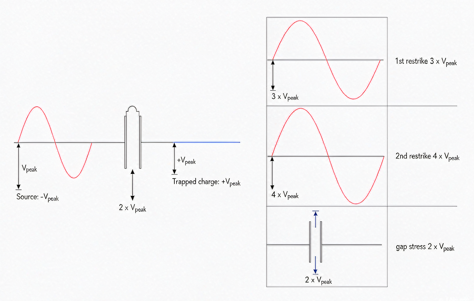
Three consequences follow, and they land on different budgets:
None of this appears in a short-circuit test report, which is why utilities that switch shunt banks frequently treat the C2 certificate as a mandatory document rather than a nice-to-have.
Four situations account for most of the capacitive switching specified in practice, and each stresses a different rating.
Which rating binds depends on voltage class: at 40.5 kV cable charging governs, so the class matters more than the number; at 245 kV line charging governs and the number itself is large; at 420 kV both reach 400 A and the duties converge.
Six items, all of which should be answered in the quotation rather than discovered at commissioning.
For a 72.5 kV cable-heavy substation the practical answer is usually a live tank unit with a full set of capacitive ratings — a 72.5 kV breaker rated 4,000 A with high breaking capacity covers both the fault level and the 125 A cable-charging duty the standard prefers at that voltage. At 252 kV, where line dropping and bank switching both matter, a 252 kV split-type unit rated 4,000 A is the equivalent starting point, and the capacitive ratings need checking against actual line length rather than assumption.
The pattern across all of this is worth stating plainly: capacitive switching is the one duty where a breaker’s headline short-circuit rating is close to irrelevant. The IEC 62271-100 standard treats it as a separate qualification for that reason, and the type test programme that establishes it is longer and more repetitive than the fault-clearing series.
A 40 kA breaker cannot necessarily break 50 A because the two duties stress different things. Fault clearing is about energy, pressure and arc control at high current. Capacitive switching is about dielectric recovery across a short gap against a recovery voltage of twice the system peak, with a trapped charge waiting to escalate if the gap fails.
The discipline is short: get all four current ratings, get the class with its report, check that T60 preconditioning was part of it, and match rated voltage and earthing condition to the site. Everything else — brand, enclosure type, mechanism — is secondary to those four documents. If you are specifying for a capacitor bank, a cable-heavy network or a line-dropping duty, send us the voltage class, the bank or cable data and the switching frequency, and we will tell you which ratings bind before you go to quotation. The full range is in the SF6 circuit breaker library, and SF6 vs vacuum covers how vacuum interrupters behave on the same duty.
It is the making and breaking of small currents flowing into capacitance — an unloaded overhead line, an unloaded cable, or a shunt capacitor bank. The current is small but the load stores charge, so at current zero the load-side voltage is at its peak and the gap must withstand about twice system peak shortly afterwards.
Both are restrike-probability classes. C1 means low probability, demonstrated by 24 low-current operations and 24 full-current close–open operations, with up to one restrike permitted. C2 means very low, demonstrated after T60 preconditioning with a much longer full-current series and no restrikes at all.
Because the two duties depend on different physics. At tens of kiloamps the arc supplies the energy that pressurises the quenching chamber. At tens of amps there is almost no arc energy, so the blast must come from the mechanical puffer volume, and the gap at current zero is only a few millimetres wide.
Cable charging. The two are separate because cable capacitance per kilometre is much higher than line capacitance. At 40.5 kV the preferred cable-charging rating is 50 A against 10 A for line charging, so a cable feeder reaches the limit far sooner than an overhead line of the same length.
Both, differently. Inside the breaker a restrike is an internal flashover that erodes the nozzle and contacts and leaves decomposition products in the gas. On the bank side each restrike can raise the trapped voltage, pushing units and reactors several times above design voltage.
Usually yes. Energising a bank next to an already-charged bank produces inrush at a few kilohertz, limited mainly by the inductance between the banks. The preferred inrush making rating is 20 kA peak at around 4,250 Hz; a series reactor is the normal way to stay inside it and protect the closing contacts.