SF6 Gas Density Monitor: Alarm Pressure, Lockout Pressure & Density Relay Calibration
Published: Author: Lisa
A pressure gauge on an SF6 breaker tells you almost nothing on its own. On a cold morning it will read low on a perfectly healthy unit, and on a hot afternoon it will read high on one that is slowly leaking. What the breaker actually needs to know is how much gas is inside — the density — and that is the single job of the SF6 gas density monitor.
This article covers the device end to end: why density is the correct measured quantity, how a compensated relay derives it, how the two-stage alarm and lockout logic should be set, what calibration actually verifies, and why so many “gas low” alarms turn out to be instrumentation rather than leakage. It applies to the density relays fitted on outdoor HV breakers across the SF6 circuit breaker range, from 40.5 kV distribution units to 252 kV transmission equipment.
Why the device monitors density, not pressure
SF6 dielectric strength and arc-quenching ability depend on the number of gas molecules per unit volume between the contacts, not on the force those molecules exert on a gauge. Density is that quantity. Pressure is density multiplied by temperature, which is why a gauge alone cannot distinguish a healthy breaker in winter from a leaking one in summer.
The arithmetic is not subtle. For a sealed compartment, density is fixed unless gas escapes. Pressure, by contrast, moves with ambient temperature by roughly 0.7% per kelvin at constant volume — around 20% across a −20 °C to +40 °C ambient swing. That is far larger than the gap between normal operation and the alarm threshold, so any device that simply measures pressure and calls it density will produce alarms that mean nothing.
Ratings are defined at a reference temperature of 20 °C. A breaker rated at 0.5 MPa means 0.5 MPa gauge at 20 °C, at the specified density. Everything the density monitor does is an attempt to recover that 20 °C value from a measurement taken at whatever temperature the site happens to be.
How a density monitor works
The compensated mechanical relay
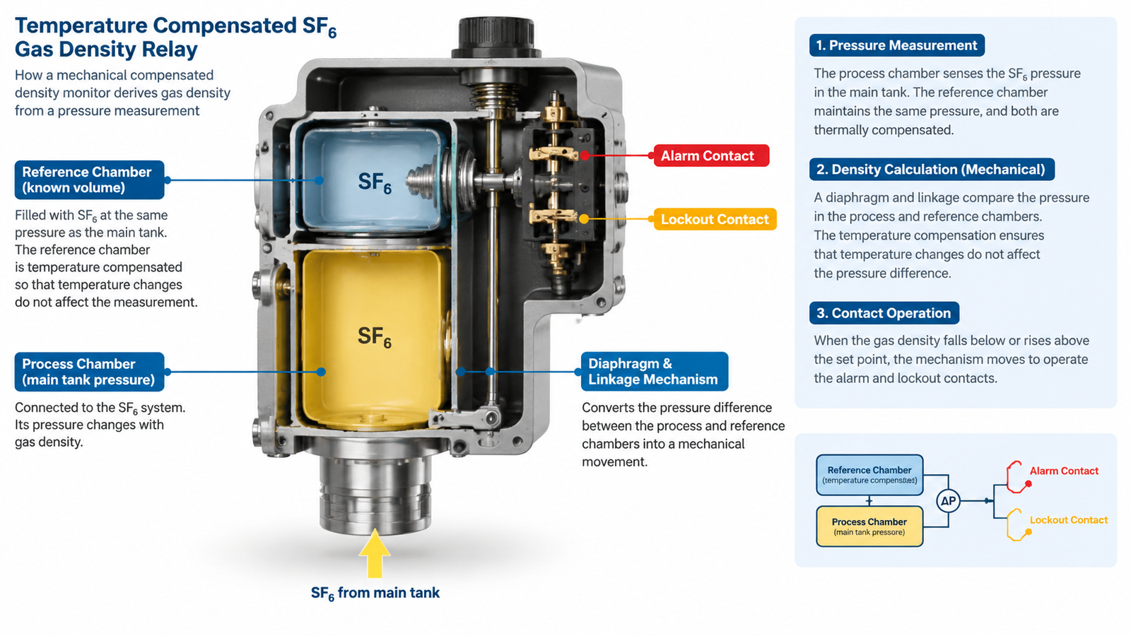
Most outdoor HV breakers use a mechanical density relay. The construction is a pressure switch with a reference:
A sealed reference chamber is filled with SF6 at the rated density during manufacture, then permanently sealed.
A bellows or diaphragm assembly separates the reference chamber from the breaker’s gas compartment.
The force balance between reference and compartment depends only on the density difference between them, because both volumes experience the same temperature.
Micro-switches actuate at defined displacement positions, producing the alarm and lockout signals.
The elegance of the design is that temperature cancels. When the whole device cools, the reference chamber pressure falls at the same rate as the compartment pressure, the bellows stays in balance, and no signal is produced. Only a real loss of molecules from the compartment unbalances it. This is genuine density measurement with no electronics, no power supply, and no firmware — which is why the mechanical relay remains the default on transmission equipment.
The electronic density transmitter
Electronic versions combine a pressure sensor with a temperature sensor and compute density using the SF6 compressibility factor. They offer advantages a mechanical relay cannot: continuous readings instead of discrete contacts, trend data for condition monitoring, remote indication over SCADA, and self-diagnostics.
The trade-off is dependency. An electronic transmitter needs a power supply, a communication path, and a calibration that can drift. In practice, many modern installations use both — a mechanical relay for the hard-wired trip and lockout path, and a transmitter for monitoring. Keeping the protection function on a passive device and the monitoring function on an active one is a sound division of labour.
Where the relay sits
The relay is mounted on the gas compartment it protects, usually on the breaker tank or on a small manifold. Location matters: a relay mounted on a long capillary in a different thermal environment from the tank will read a temperature gradient as a density change. Short, direct mounting with the relay body at tank temperature is the arrangement that avoids this class of false alarm.
The two-stage logic: alarm and lockout
Every density relay has two thresholds, and confusing them is the most common specification error. They serve different purposes and drive different actions.
Alarm stage — the top-up signal
The alarm contact closes when density falls to the first threshold. Its meaning is: the breaker is still fully capable, but the charge needs attention. The correct response is to schedule a top-up, investigate the leak, and record the event — not to remove the breaker from service.
Typical margin below rated density is 8–10%. For a 0.5 MPa rating, alarm is normally around 0.45 MPa; for 0.6 MPa, around 0.55 MPa. The margin is sized so that a normal year of slow leakage between maintenance intervals does not reach it.
Lockout stage — the blocking signal
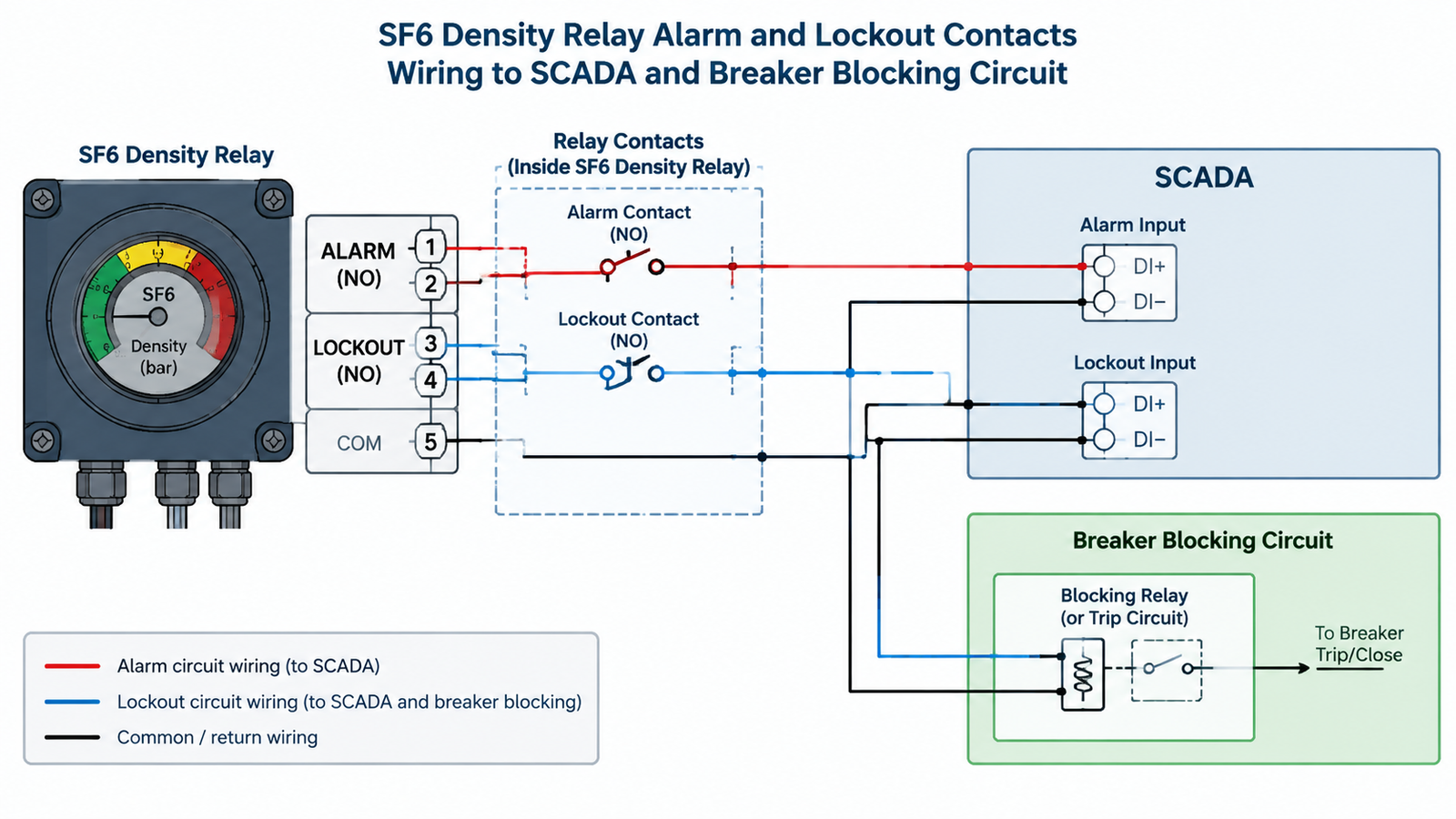
The lockout contact closes at the second threshold. Its meaning is: dielectric strength is no longer assured; the breaker must not be operated. The signal is hard-wired to block open and close commands, and often to block the reclose relay and the disconnector interlocks as well.
Typical margin is 15–20% below rated density. For 0.5 MPa, lockout is around 0.40 MPa; for 0.6 MPa, around 0.50 MPa. The gap between alarm and lockout is usually 0.05 to 0.08 MPa — enough for an orderly response, not enough to allow the breaker to be operated at reduced insulation for long.
Rated filling pressure (20 °C)
Alarm (typical)
Lockout (typical)
Gap
0.40 MPa
0.36 MPa
0.32 MPa
0.04 MPa
0.50 MPa
0.45 MPa
0.40 MPa
0.05 MPa
0.60 MPa
0.55 MPa
0.50 MPa
0.05 MPa
0.70 MPa
0.64 MPa
0.58 MPa
0.06 MPa
These are typical values for orientation. The authoritative numbers are on the rating plate and in the manufacturer’s density curve for that specific compartment — and they differ between the interrupter chamber and any separate busbar or CT compartment on the same breaker.
One relay per compartment
A three-pole breaker with independent gas compartments needs three density relays, not one. Linking three compartments to a single relay means a leak in one pole is diluted by the healthy charge in the other two, and the alarm arrives when all three are depleted. This is a design mistake that only becomes visible years later, when a pole fails its dielectric test.
Alarm schedules a top-up; lockout blocks operation. They must never share a circuit.
Temperature compensation and why winter causes false alarms
A correctly compensated relay does not alarm in cold weather. When one does, the cause is usually one of four things.
Relay not actually compensated. A pressure switch installed in place of a density relay, or a relay whose reference chamber has lost its charge, behaves like a plain pressure switch and alarms at low ambient.
Thermal gradient between relay and tank. A relay on a capillary or on a sun-exposed bracket sees a different temperature from the gas it is judging.
Liquid SF6 present. Below the liquefaction temperature, gas becomes liquid, and the pressure no longer follows the gas law the compensation assumes. This is a real physical effect, not an instrument fault — and it is why cold-climate sites need heater blankets or a lower filling pressure.
Moisture or ice in the capillary. Condensed water freezes and blocks or biases the sensing path.
Distinguishing the four requires the temperature at the time of alarm and the site’s ambient record. A relay that alarms at −25 °C and resets by mid-morning is behaving consistently with liquefaction; one that alarms at +15 °C is an instrument problem.
Calibration and verification
At commissioning
Verify each relay before energisation. The standard method uses a portable gas filling and calibration device: connect to the relay’s test port, set the pressure to the value corresponding to the alarm threshold at the measured temperature, and confirm the contact operates. Repeat at the lockout threshold and on the reset path.
Two checks are routinely skipped and should not be:
Contact function in the actual circuit. Confirm the alarm and lockout contacts actually reach the relay, the SCADA point, and the blocking circuit — not just that the micro-switch clicks.
Setpoint recorded at commissioning temperature. Record the gauge reading, the ambient temperature, and the computed 20 °C equivalent. Without that baseline, every future comparison is guesswork.
Periodic verification
Mechanical density relays are stable devices, but they are not exempt from verification. A three to five year interval is common practice, tightened to one to two years where the site has a history of relay faults or extreme temperature cycling. Verification follows the same procedure as commissioning: apply known pressures at known temperatures and compare the operating points against the manufacturer’s curve.
Verification is not the same as adjustment. A relay that operates within tolerance is left alone; one that has drifted is replaced rather than re-set in the field, because field adjustment of a sealed reference chamber destroys the traceability that made the device trustworthy in the first place.
What the calibration actually proves
A successful calibration confirms that the relay switches at the right density. It does not confirm that the compartment holds gas, that the alarm reaches the control room, or that the blocking circuit works. Those are three separate tests, and all four together are what “the gas monitoring system works” means.
A sealed reference chamber cancels temperature, so only a real loss of gas unbalances the relay.
Troubleshooting false alarms and drift
Symptom
Probable cause
Check
Alarm only in cold weather, resets when warm
Liquefaction or uncompensated relay
Compare alarm temperature against the liquefaction curve for the rated pressure
Alarm on all three poles at once
Common wiring, common relay, or genuine system-wide under-fill
Verify compartment independence; check commissioning charge records
Alarm fluctuates without temperature change
Loose capillary, vibration, contact bounce
Inspect mounting; check contact continuity with a logger
Reading drifts slowly downward over months
Genuine leak, or reference chamber loss
Leak survey with detector; if no external leak, suspect the relay
Alarm after a fault interruption
Pressure transient from arc energy
Confirm recovery to normal within minutes; if not, gas analysis is due
Lockout without prior alarm
Alarm stage failed or was never wired
Test both stages independently
The single most useful diagnostic habit is trend recording. A relay that reads the same 20 °C equivalent density every quarter for five years and then drops 0.02 MPa in six months is telling you something, even if it is still above the alarm threshold. That trend is only visible if someone writes the number down — which is why the commissioning baseline matters more than the alarm setting.
Specification checklist
When specifying a breaker, state these six items explicitly rather than accepting “standard density relay”.
One relay per gas compartment, with independent alarm and lockout contacts.
Setpoints in MPa at 20 °C, for both stages, per compartment type.
Contact rating and type — normally open or normally closed for alarm, and fail-safe orientation for lockout.
Operating temperature range matching the site minimum, with heater provisions where liquefaction is possible.
Test port for verification without depressurising the compartment.
Monitoring option — a density transmitter or analogue output if the site is going to be remotely monitored.
A 0.5 MPa rated 40.5 kV breaker is a good example of why the setpoints must come from the manufacturer rather than from a generic table: at that rating the alarm and lockout values sit close to the liquefaction point in cold climates, and the heater and relay settings have to be designed together. The LW8-40.5 with 0.5 MPa rated gas pressure publishes both the pressure rating and the cold-climate provisions for exactly this reason.
Conclusion
The density monitor is a small device with an outsized role: it is the only component that knows whether the breaker can still interrupt fault current. Treat it as protection equipment, not as an accessory. Set both stages from the manufacturer’s curve, verify them at commissioning with the actual control circuit, record the baseline, and trend the readings between verifications.
Do that and a gas alarm means something. Skip it and you will spend maintenance budget chasing winter false alarms while a real leak goes unnoticed. For the gas side of the same job — filling, recovery, moisture limits, and decomposition products — see SF6 gas handling on site and SF6 gas quality: purity, moisture and decomposition. For the wider maintenance rhythm, the maintenance checklist sets out intervals, and the article library covers the rest of the equipment.
FAQ
What is the difference between an SF6 pressure gauge and a density monitor?
A pressure gauge shows pressure at the current temperature and requires manual correction to be meaningful. A density monitor compensates internally and indicates whether the mass of gas in the compartment has changed. Only the second can be used for alarm and lockout decisions.
At what pressure should the alarm stage be set?
Typically 8–10% below the rated filling pressure at 20 °C — around 0.45 MPa for a 0.5 MPa breaker. Use the manufacturer’s density curve for the specific compartment, because interrupter chambers and busbar compartments often have different ratings.
Why does my breaker alarm only in winter?
Either the relay is not temperature compensated, or the compartment is near its liquefaction temperature and gas is condensing. The second case is a design issue rather than a fault, and is resolved with heater blankets, a lower filling pressure, or a gas mixture.
How often should a density relay be verified?
Every three to five years is common practice, with a shorter interval where relay faults have occurred before. Verification uses a portable filling device at the relay’s test port and compares operating points against the manufacturer’s curve.
Can the alarm and lockout contacts share a circuit?
No. They must be independent and separately wired, because they trigger different actions: alarm schedules a top-up, lockout blocks operation. Sharing a circuit means either nuisance lockouts or an unblocked breaker running at reduced insulation.
Does a density relay detect a slow leak?
Yes, eventually — but only after enough gas has been lost to move the reading. A leak survey with a portable detector finds the leak years earlier. Use the relay as the safety net and the survey as the diagnostic tool.
Why a breaker rated 40 kA may still restrike on 50 A: the four capacitive duties, preferred current values by voltage class, C1 vs C2 tests and what to check.