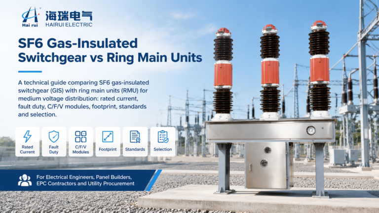
SF6 circuit breaker testing exists because a breaker is the last line of defense in a substation. Everything upstream — protection relays, CTs, trip circuits — is only as good as the device that finally opens the circuit. If it closes on a fault and fails to clear it, the fault current keeps flowing until something else fails, and that something is usually a transformer, a busbar, or a person standing nearby.
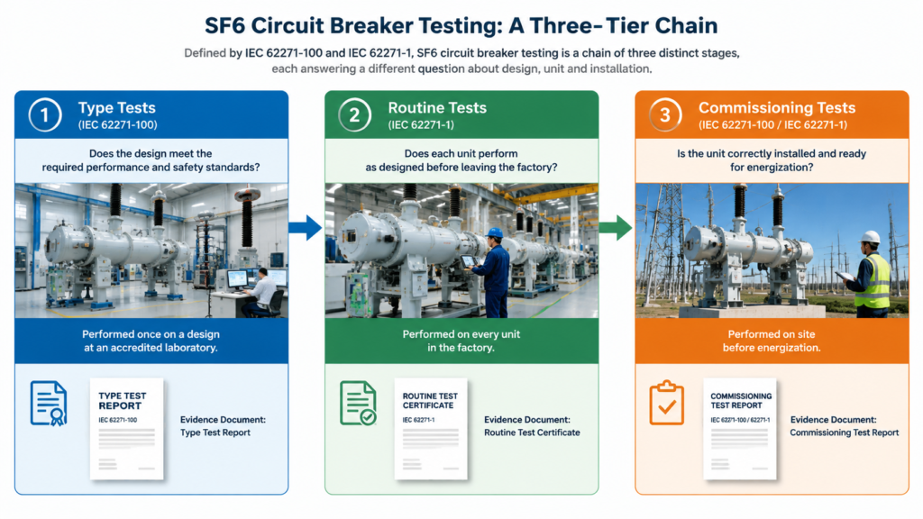
Testing an SF6 breaker is not one event. It is a chain of three distinct stages, each answering a different question: does the design work, does this particular unit work, and does the installed installation work. Buyers who treat the three as interchangeable end up either overpaying for redundant tests or, far worse, accepting a test report that proves nothing about the unit sitting in their yard.
This guide walks the full chain — type tests, factory routine tests, and site commissioning tests — with the specific test items, the values that matter, and what to look for when a supplier hands you a test certificate. It is written for substation engineers, EPC commissioning teams, and procurement staff who need to know whether the document in front of them is worth the paper it is printed on.
What SF6 Circuit Breaker Testing Actually Proves
The three tiers of testing are defined by the standards but differ in who performs them, when, and what evidence they leave behind. IEC 62271-1 sets the common requirements for high-voltage switchgear; IEC 62271-100 covers circuit-breaker duties specifically. IEEE C37.09 plays the same role as a test procedure in the North American market, and ANSI/NETA ATS defines the field acceptance values utilities use on site.
Test tier
Who performs it
When
What it proves
Document you receive
Type tests
Manufacturer, at an independent or accredited laboratory
Once per design, before series production
The design can survive its rated duties
Type test report or certificate, usually referencing KEMA, CESI, or a national lab
Routine tests
Manufacturer, on the production line
Every single unit, before shipment
This unit is built correctly and leak-free
Factory routine test report with serial number
Commissioning tests
EPC or utility test team
After installation, before energization
The installed breaker and its circuits work together
Commissioning protocol and as-left baseline records
Notice what the table implies. A type test certificate is a statement about a design, not about your breaker. A routine test report is a statement about your breaker, but only as it left the factory. Neither tells you whether the transport, the foundation, the control wiring, or two years of warehouse storage did any damage. That gap is what commissioning tests close — and it is the tier buyers most often skip when a project is running late.
Type Tests: What the Design Has to Survive
Type tests are destructive by design. The same breaker, or a representative unit, is pushed to its ratings and sometimes past them until something gives. The results certify the design family, which is why a supplier can sell the same model for years on a single certificate — provided the design has not changed.
Breaking and making duties
The centerpiece of any IEC 62271-100 type test report is the breaking duty sequence. Short-circuit breaking tests are run at fractions of the rated short-circuit current: T10, T30, T60, and T100 — 10, 30, 60, and 100 percent. On a unit rated for high breaking capacity, such as a 4000 A 72.5 kV SF6 circuit breaker, the T100 duty is the one that sets the upper limit on the design. It is a common misconception that the low-current duties are the easy ones. They are not. At 10 percent of rated current the transient recovery voltage rises faster and steeper, stressing the dielectric recovery of the gap rather than the thermal energy of the arc. A breaker that passes T100 can still fail T10.
Short-line fault duties add a second dimension. When a fault occurs a short distance down an overhead line, the line itself acts as a distributed capacitance and produces a very steep recovery voltage across the interrupter. IEC 62271-100 covers these as dedicated short-line fault duties, and for transmission-class breakers they are non-negotiable. Making capacity is tested alongside — the peak current the breaker can close into without welding its contacts.
For a unit specified with a 40 kA short-time withstand current, such as the LW9-72.5 outdoor SF6 breaker, the type test report should show the full duty sequence, not a summary line. If a supplier’s certificate lists only a breaking capacity figure with no duty breakdown, you are looking at a data sheet, not a test report.
Mechanical and electrical endurance classes
IEC 62271-100 grades endurance rather than stating a single life figure. Mechanical endurance is expressed as class M1, covering 2,000 operating cycles, or class M2, covering 10,000. The test is run without current and without re-lubrication, and it is followed by a timing and travel check to confirm the mechanism has not drifted.
Electrical endurance is graded as E1 or E2, with E2 representing the more demanding service duty where the interrupter must survive a longer sequence of short-circuit operations. Capacitive current switching is graded separately as C1 or C2, and for breakers used to switch capacitor banks or unloaded lines the C2 class — the lower restrike probability class — is the one worth insisting on.
These class letters are the most useful part of a type test certificate for a buyer, because they translate directly into maintenance intervals and expected life. A breaker rated M2 at 10,000 operations will run for decades on a switching duty that would consume an M1 mechanism in a few years. The mechanical endurance class is one of the clearest places to see the difference between a distribution-grade design and a transmission-grade one — for example between a 40.5 kV mechanism rated for 3,000 operations and a heavier 72.5 kV design built for sustained duty.
Dielectric and temperature-rise type tests
Dielectric type tests confirm the insulation system: power-frequency withstand on the main circuit, lightning impulse withstand, and above 245 kV a switching impulse withstand test, since slow-front overvoltages dominate insulation design at extra-high voltage. These are the tests behind the impulse withstand figures on the nameplate — the numbers you compare when specifying a breaker for a location with a particular lightning exposure, such as a 252 kV breaker rated 1050 kV lightning impulse withstand.
Temperature rise is tested at rated continuous current to confirm that the contacts, terminals, and enclosure stay within the permissible temperature limits. It is a slow, unglamorous test that quietly determines whether a breaker will be reliable at full load in a hot climate, and it is worth checking that the certificate covers it at the rated current you are buying, not a lower one.
Routine Tests: What Every Unit Faces Before Shipping
Routine tests are run on every production unit. They are not designed to break anything; they are designed to catch manufacturing defects — a misaligned contact, a slow mechanism, a porous casting, a wiring error in the control cabinet. The routine set is short and standardized, which is exactly what makes it auditable.
The core factory routine set
Dielectric test on the main circuit. A power-frequency withstand applied to each pole, both phase-to-ground and across the open gap, at the factory test level defined for the voltage class.
Main circuit resistance measurement. A DC voltage-drop measurement at not less than 100 A through each pole, confirming clean contact interfaces and correct assembly torque.
Gas tightness test. The assembled breaker is filled and monitored for leakage, either by pressure decay or by a tracer method, against the specified annual leak rate.
Mechanical operating test. A defined number of close and open operations, plus timing and travel measurement, to confirm the mechanism operates within the specified windows.
Auxiliary and control circuit test. Verification of wiring, interlocks, auxiliary switch sequences, heater operation, alarm contacts, and the anti-pump function.
Visual and dimensional inspection. Nameplate data, paint and finish, clearances, and completion of the bill of materials.
Each of these appears in the report against the unit’s serial number. That serial number is the single most important thing to verify when the breaker arrives: a routine test report for a different serial number, or with the serial number field left blank, is not evidence about your breaker.
Extra checks for multi-break and resistor-fitted designs
Breakers with more than one interrupter per pole carry additional hardware, and the routine test scope grows with it. Grading capacitors, which share the voltage evenly across the series breaks, are measured for capacitance and dissipation factor. Where pre-insertion or opening resistors are fitted to limit switching overvoltages, the factory verifies both the resistor value and the insertion and bypass timing — the resistor must be in circuit for the right window, measured in milliseconds, or it does nothing useful.
These additions are why a high-voltage breaker’s routine test report is longer than a distribution breaker’s. When comparing quotes across voltage classes, compare the routine test scope as well as the price. A cheaper offer with a thinner test scope has simply moved cost from the factory to your site.
Commissioning Tests: Proving the Installed Breaker
Commissioning is where the breaker stops being a product and becomes part of a system. The tests here follow the manufacturer’s manual and utility practice rather than the standard’s type-test procedures, and they produce the baseline that all future maintenance will be compared against. Run them properly once and every later measurement has a reference point.
First-trip and mechanical operation
The first-trip test is exactly what it sounds like: capture the breaker’s behaviour on the very first operation, before the mechanism has been exercised. A breaker that has been in storage for a year may show high friction, sluggish timing, or a sticky latch on that first operation, and those symptoms disappear once it has been cycled a few times. If you only measure after twenty operations, you will never see them — and you will have destroyed the evidence that would have justified a warranty claim.
After the first trip, the mechanical sequence covers close, open, close-open, trip-free operation, and the anti-pump function. Trip-free operation confirms the breaker will still open if a trip signal arrives while a close command is being held — a protection requirement, not a convenience. Minimum pickup voltage tests then verify that the close and trip coils operate at their specified minimum control voltage; under IEC 62271-100 a closing operation must be reliable at 85 percent of rated control voltage, and the trip release has its own lower threshold.
Timing, travel and coil signatures
Timing tests measure opening time, closing time, and pole discrepancy across all three poles simultaneously. For a high-voltage puffer breaker, an opening time in the range of 40 to 60 milliseconds — roughly two to three cycles at 50 Hz — is typical, and the exact window is in the manufacturer’s data. What matters more than the absolute number is the spread: pole discrepancy is normally held within a couple of milliseconds, because an asymmetric opening leaves the last pole to clear carrying more than its share of the fault current.
Travel and velocity curves come from a motion transducer on the operating rod, and they show whether the mechanism is delivering the speed profile the interrupter needs. A velocity curve that is soft at the start of the opening stroke points to a lubrication or linkage problem that timing alone can hide.
Coil current signatures complete the picture. The shape of the trip coil current trace — the initial rise, the plateau, and the point where the plunger seats — reveals latch condition, coil health, and trip circuit resistance, and it is the fastest way to confirm that the mechanism behaves as the spring, pneumatic, or hydraulic operating mechanism was designed to. A coil signature that differs between poles, or between the as-found and as-left tests, is an early warning that costs nothing to catch at commissioning and a great deal to catch after a failed operation.
Contact resistance and dynamic resistance measurement
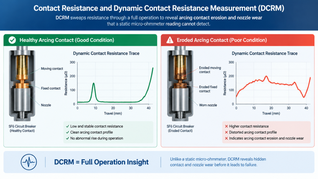
Static contact resistance is measured with a micro-ohmmeter at not less than 100 A through each pole. Healthy main contacts typically sit well below 50 micro-ohms, and the useful comparison is between poles and against the factory figure, not against an absolute number. A pole reading noticeably higher than its siblings points to a contact alignment or surface problem.
Static resistance alone, however, cannot see the arcing contact. That is what dynamic contact resistance measurement (DCRM) is for. DCRM sweeps resistance continuously through a full opening or closing operation, producing a resistance-versus-travel trace that shows the transition from main contact to arcing contact and the condition of the nozzle. Eroded arcing contacts and a worn nozzle show up as a distorted trace even when the static value still looks perfectly normal. On high-voltage SF6 breakers, where the interrupter cannot be opened for inspection, DCRM and gas analysis are the two most valuable diagnostic tools available.
The interrupter condition that DCRM reveals depends heavily on the interrupting principle — puffer, self-blast, or thermal expansion designs wear differently — so the trace is read against the expected signature for that interrupter type rather than a generic template.
Insulation and dielectric checks on site
Field insulation testing covers resistance pole-to-pole, pole-to-ground, and across open poles, followed by a power-frequency withstand test where the specification calls for one. The field test voltage is normally applied at a fraction of the factory level — commonly around 80 percent — because the site is not a laboratory and the margin protects the insulation while still proving it. On dead-tank designs, bushing power factor and capacitance tests are added, along with checks on the bushing current transformers. On gas-insulated switchgear, partial discharge measurement, typically by the UHF method, is the standard addition.
SF6 Gas Tests: The Diagnostic Most Buyers Underweight
In an SF6 breaker the gas is not just an insulator — it is also the arc-quenching medium. That dual role makes gas condition a primary diagnostic rather than routine housekeeping. Four parameters carry almost all the information.
Parameter
What it indicates
Typical acceptance reference
Density (temperature-corrected)
Interrupting and insulating capability. Density, not raw pressure, is the correct measure, since pressure varies with ambient temperature while density does not.
Within the manufacturer’s rated density band for the compartment, read from the density monitor
Moisture / dew point
Dielectric strength and the formation of decomposition products. Moisture lowers withstand voltage and, combined with arcing, generates acidic by-products.
Commonly in the order of 150 µL/L for compartments open to the interrupter and 250 µL/L for others; measured at least 48 hours after filling
Purity
Whether the gas in the breaker is actually the specified SF6, or has been diluted with air during filling or top-up. Air contamination reduces dielectric strength.
High purity, typically above 97 percent by volume for gas in service, against the new-gas specification in IEC 60376
Decomposition by-products (SO2, H2S, CO)
Internal arcing, partial discharge, or hot spots. SO2 is the workhorse indicator: a rising level means the gas has been through an arc.
Low and stable; a rising trend between tests matters more than the absolute number
The most common mistake is treating a gas test as pass or fail against a single number. These values are baselines. A moisture reading of 120 µL/L that was 40 µL/L six months ago is a more urgent finding than a stable 200 µL/L that has not moved in three years, because it means something has changed inside a sealed system. Gas reclaimed for reuse is judged against IEC 60480, which sets the criteria for what can go back into equipment and what must be processed or disposed of.
Gas analysis is also the earliest available warning of internal trouble in a sealed breaker. Because you cannot open an SF6 interrupter for inspection without a full workshop overhaul, the gas is your only continuous window into what is happening around the arcing contacts.
Gas Tightness and Leak Rate Verification
SF6 is a potent greenhouse gas, and leakage is both an environmental and a commercial problem. Tightness is verified at the factory on every unit, and again on site after assembly, because joints that were perfect in the factory can weep after transport and erection.
Field leak detection uses a sniffer or infrared imaging camera to survey flanges, valve stems, density monitor connections, and the pressure relief device. The result is expressed as an annual leak rate for the breaker, and specifications commonly call for no more than 0.5 percent per year, with stricter limits for larger gas inventories. Where a leak is suspected but not located, a bagging or accumulation test over a defined period gives a quantitative answer rather than a yes-or-no sniff.
The density monitor deserves its own check. It is a mechanical instrument that must alarm and lock out at the correct density thresholds, and it drifts. Verify the alarm and lockout settings against the manufacturer’s data during commissioning, and confirm that the signals actually reach the control room rather than terminating in a cabinet.
How to Read an SF6 Breaker Test Report
Test reports are a procurement document as much as an engineering one. The following checks catch most of the problems that reach a site.
Serial number match. The routine test report must carry the serial number stamped on the breaker you received. Mismatches and blank fields are common in rushed shipments.
Test dates and revision level. A type test certificate issued before a design change does not cover the current build. Ask what revision the certificate applies to.
Duty breakdown, not summary figures. The type test report should show the individual breaking duties and the endurance class letters. A single headline breaking capacity number is a data sheet.
Actual measured values, not just “pass”. Contact resistance, timing, and gas tightness should appear as measured numbers with the acceptance limits alongside. A report with only tick boxes gives you no baseline to trend against later.
Accreditation of the testing laboratory. Independent laboratory certificates carry more weight than in-house ones, particularly for type tests.
Consistency across poles. The three poles should be close to each other in resistance and timing. Uniformity is the strongest single indicator of build quality.
Ask for these documents before the purchase order, not after. A supplier who can produce a complete type test certificate with duty breakdowns and a sample routine test report at quotation stage is demonstrating something that a cheaper competitor cannot.
Matching Test Scope to Voltage Class
The test scope scales with voltage, and knowing where the steps occur helps you specify sensibly. At medium voltage, contact resistance and timing carry most of the diagnostic weight, and the type test duties are comparatively limited. Above 52 kV the picture changes: interrupting duties become more demanding, the breaker may have multiple interrupters per pole with grading capacitors and pre-insertion resistors to verify, and SF6 gas quality moves to the center of the field test program. Above 245 kV, switching impulse withstand enters the type test scope, and multi-break timing has to account for several interrupters and separate resistor contacts per pole.
This is why the same test procedure document cannot simply be reused across a substation with mixed voltage levels. A commissioning plan written for 40.5 kV equipment will miss the gas analysis and grading capacitor checks that a 126 kV or 252 kV breaker requires.
Conclusion
SF6 circuit breaker testing is a chain, not a checkbox. Type tests certify that the design survives its rated duties, routine tests prove that your specific unit left the factory sound, and commissioning tests confirm that the installed breaker and its control circuits work as a system. Skip any link and you inherit an unquantified risk — usually the one that shows up during a fault, when the breaker has exactly one chance to operate.
The practical takeaway for buyers is to demand evidence at every stage and to insist on measured values rather than pass marks. The numbers you record at commissioning become the baseline for the next twenty years of maintenance, which makes the first test the most valuable one the breaker will ever have.
If you are specifying high-voltage SF6 breakers for a substation project and need the test documentation package to review before ordering, our engineering team can supply the type test certificates, sample routine test reports, and commissioning protocol for the model you are considering.
Frequently Asked Questions
What is tested on an SF6 circuit breaker?
Testing covers the gas and the electromechanical performance. On the gas side: density, moisture, purity, and decomposition by-products such as SO2. On the electrical and mechanical side: insulation resistance, contact resistance, opening and closing timing, travel and velocity, coil current signatures, gas tightness, and the control and interlock circuits. Type tests additionally cover breaking and making duties, endurance classes, and dielectric withstand.
What is the difference between a type test and a routine test?
A type test is performed once on a design, often to destruction, at an accredited laboratory, and certifies that the design meets its ratings. A routine test is performed on every production unit at the factory and confirms that this specific breaker is built correctly. A type test certificate tells you nothing about the individual unit you receive; only the routine test report does.
What contact resistance is acceptable for an SF6 breaker?
Healthy main contacts typically measure well below 50 micro-ohms. The more useful comparison is between the three poles and against the factory figure for the same unit. A pole reading significantly higher than its siblings indicates a contact alignment or surface problem and should be investigated before energization.
Why is dynamic contact resistance measurement used instead of a static test?
A static micro-ohmmeter reading measures the main contact only, at one position. Dynamic contact resistance measurement sweeps resistance continuously through the operation, revealing the transition to the arcing contact and the condition of the nozzle. It detects eroded arcing contacts and nozzle wear that a static measurement cannot see, which matters greatly on SF6 breakers where the interrupter cannot be opened for visual inspection.
How often should SF6 gas quality be tested?
Gas quality is checked at commissioning to establish a baseline, after any fault operation that involved the breaker clearing current, and then at intervals set by the maintenance plan — commonly annually or on a condition-based schedule. Trending matters more than any single reading: a value that is rising between tests indicates a developing internal problem even if it is still within limits.
Can a breaker with a valid type test certificate still fail commissioning?
Yes, and it happens regularly. Type tests say nothing about transport damage, foundation and alignment, control wiring errors, moisture ingress during storage, or a density monitor that was never calibrated. Commissioning tests exist precisely because a correctly designed breaker can still be installed incorrectly.
SF6 vs oil circuit breaker comparison: arc-quenching principles, bulk oil vs minimum oil, ratings, maintenance, fire risk, and a practical checklist for replacing legacy oil breakers with SF6 units.
Vacuum or SF6? Compare arc quenching, voltage limits, switching behaviour, maintenance, F-gas rules and cost to pick the right circuit breaker for your network.
A practical comparison of SF6 gas-insulated switchgear (GIS) and ring main units (RMU) covering modules, ratings, fault duty, standards and how to choose.