How to Select an SF6 Circuit Breaker: Ratings, Breaking Capacity & Specs
Published: Author: Lisa
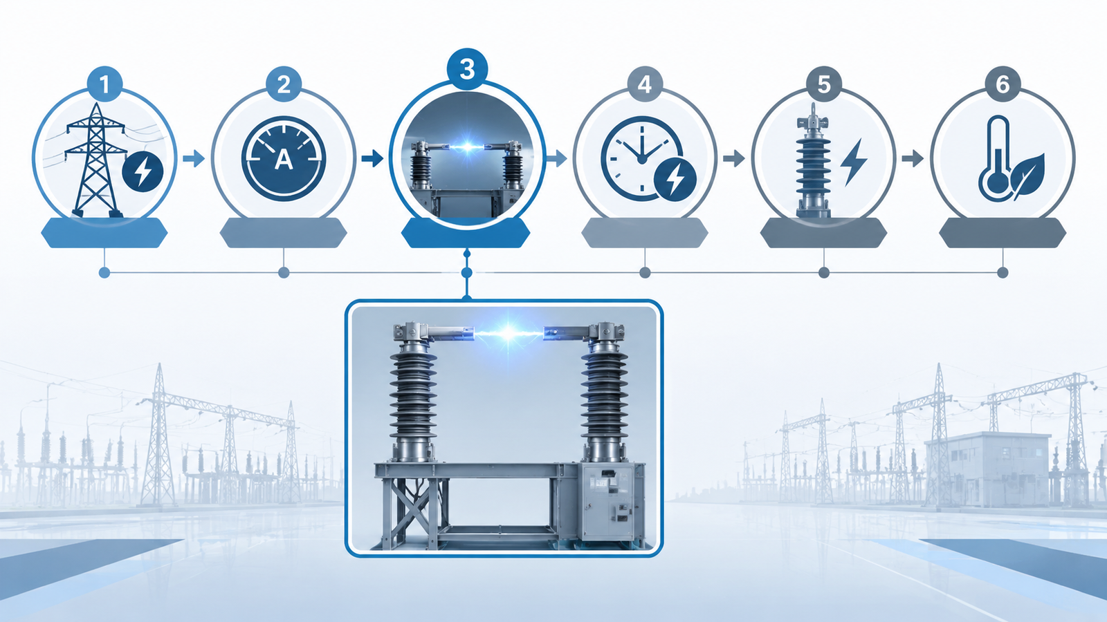
If you are specifying switchgear for a 110 kV substation, the real question is rarely “which SF6 breaker is best” — it is “which rating set is correct for this network”. Learning how to select an SF6 circuit breaker means matching six interdependent ratings to your system: rated voltage, continuous current, short-circuit breaking capacity, short-time withstand, insulation level, and the environment the breaker will actually live in. Get one of them wrong and the failure mode is not a slightly derated curve — it is a breaker that cannot clear a fault when it matters.
This guide works through the selection sequence in the order a protection engineer actually uses it, using the IEC rating definitions that govern the whole high voltage SF6 circuit breakers family. Every rating below is tied to a specific design input you can read off a system study, so the output is a spec you can hand to a supplier rather than a general wish list.
The Six Ratings That Decide an SF6 Breaker
Selection is not a single decision. It is six decisions that constrain each other, and they must be resolved in order. The table below is the short answer: what each rating protects against, and the rule that sets its minimum value.
Rating
What it protects against
Typical selection rule
Rated voltage (U_r)
Sustained system voltage and continuous overvoltage
At least the highest system voltage of the network (U_m)
Rated continuous current (I_r)
Conductor, contact and enclosure heating
Maximum load current plus 10–20% margin
Rated short-circuit breaking current
Inability to extinguish the arc during a fault
Prospective fault current plus 20–30% margin
Rated short-time withstand current (I_th, t)
Thermal and mechanical damage while relays clear the fault
At least the fault current, held for the real backup clearing time
Rated peak withstand / making current
Electromagnetic forces on contacts and busbars at first-loop peak
At least 2.5 × the breaking current
Insulation level (LI / PF withstand)
Lightning and switching overvoltages
Coordinated with the voltage class and site exposure
The rest of this article takes each row in turn and shows what actually changes in the specification.
Step 1 — Match Rated Voltage to the System Voltage Class
Rated voltage is not the same number as system voltage, and this trips up more first-time buyers than any other rating. A 35 kV network is served by a 40.5 kV breaker. A 110 kV network is served by a 126 kV breaker. The rated voltage must sit above the highest system voltage the network can sustain, because the breaker has to hold off continuous overvoltage — not just the nominal figure on the drawing.
Why the next class up is the correct class
Insulation coordination is designed around the highest system voltage for the equipment class, not around nominal operating voltage. Selecting a breaker rated exactly at nominal leaves no dielectric margin for the overvoltage that follows a load rejection or a single-phase fault elsewhere on the network. The stepped ladder — 12 kV, 24 kV, 40.5 kV, 72.5 kV, 126 kV, 252 kV — exists precisely so that each step gives a defined margin above the system level it serves. If you are still mapping system voltages to breaker classes, the SF6 circuit breaker voltage classes breakdown covers the full range from 12 kV to 800 kV.
Step 2 — Size the Rated Continuous Current
Continuous current rating determines how much load the breaker can carry indefinitely without exceeding its temperature limits. The design input is the maximum load current — normal peak, not average — plus a margin. A 10–20% margin is the usual working figure, and it is not padding: it absorbs the load growth between commissioning and the first major upgrade, and it covers the difference between the ambient temperature used in the rating and the temperature inside the switchgear enclosure.
For heavily loaded transformer incomers and tie bays on a 126 kV network, that calculation often lands above 2500 A, which is where a high-current variant becomes the practical choice. A breaker such as the LW36-126 with a 3150A rated current keeps peak demand inside design limits without resorting to parallel breaker arrangements or an early substation upgrade. Note that the current rating and the fault ratings are independent: a higher continuous current does not automatically come with a higher breaking capacity, so confirm both against your study.
Step 3 — Set the Short-Circuit Breaking Capacity
The short-circuit breaking current is the core safety rating — the maximum fault current the interrupter can extinguish without damage. The design input is the prospective fault current at the breaker’s location, calculated from source impedance and transformer impedance. Apply a 20–30% margin. If the study gives 40 kA, specify 50 kA; if it gives 32 kA, a 40 kA breaker gives you the margin and matches the standard rating step.
Symmetrical versus asymmetrical breaking current
System studies usually report symmetrical (AC component) fault current, while the breaker’s rating is defined against the symmetrical breaking current at contact separation. Near a generator, the DC component decays slowly and the asymmetrical current can be substantially higher than the symmetrical figure at the moment the contacts part. If your fault point is electrically close to generation, check the percentage DC component and confirm the breaker’s rating is defined for that duty — this is a conversation to have with the supplier using your study output, not an assumption to make.
Making capacity and peak withstand
Breaking capacity and making capacity are not the same test. Closing onto a fault is mechanically harder on the contacts than opening one, because the full first-loop peak current flows through contacts that are still seating. The rated peak withstand and making current are therefore specified at roughly 2.5 times the breaking current for a 50 Hz system, and this value drives the mechanical design of the contact assembly and the busbar support spacing. A 40kA short-circuit breaking capacity rating on a 126 kV outdoor breaker is the reference point for substations specified around a 40 kA fault level, and it comes with the matched peak and withstand values that the rating implies.
Flow diagram of the SF6 circuit breaker selection sequence, from system voltage through continuous current and breaking capacity to short-time withstand and insulation level
Step 4 — Check Short-Time Withstand Against Your Protection Time
This is the rating buyers most often leave blank, and it is the one that decides whether the breaker survives a fault that its own protection does not clear. The rated short-time withstand current is the current the breaker can carry while remaining closed — thermally stable and mechanically intact — for a stated duration, conventionally written as I_th for t seconds.
The selection rule is straightforward: the withstand current must be at least the prospective fault current, and the duration must cover the actual clearing time of the backup protection, not the primary protection. If the primary relay clears in 100 ms but the upstream backup takes 2.5 s, a breaker rated 40 kA/1 s is being asked to do something it was never tested for. A rating such as the 40kA/3s short-time withstand on the LW36-126 exists for exactly this scenario: it lets the breaker stay closed and stable while a backup protection sequence completes.
Step 5 — Confirm the Insulation Level
Insulation level is expressed as two numbers: the rated lightning impulse withstand voltage (LI) and the rated power-frequency withstand voltage (PF), each stated to earth and across the open contact gap. These are type-test values that prove the dielectric strength of the interrupter and the external insulation.
The values step up sharply with voltage class. In this product family, a 40.5 kV breaker is proven at 95 kV power-frequency withstand, a 72.5 kV breaker at 350 kV lightning impulse to earth and 350 + 60 kV across the fracture, and a 252 kV breaker at 1050 kV lightning impulse to earth with 1050 + 206 kV across the open gap. All of these figures sit inside the framework of IEC 62271-100 rating definitions, which is also the standard that defines every current rating discussed above. If a supplier quotes an insulation level without naming the standard it was tested to, ask for the type-test report — the type and routine tests behind a rating are what make the number meaningful.
Step 6 — Choose Operating Mechanism, Pole Count and Mounting
Once the electrical ratings are fixed, the mechanical specification narrows quickly. Three decisions remain: how the breaker is operated, how many poles it has, and how it is mounted.
Operating mechanism. Spring mechanisms dominate the 35 kV to 126 kV range because they are self-contained, reliable and low-maintenance. Hydraulic mechanisms appear where very high output energy or tight operation-time scatter is required, typically at 220 kV and above. Pneumatic mechanisms are now rare in new installations. The comparison is covered in detail in this breakdown of SF6 circuit breaker operating mechanisms.
Pole count and configuration. Three-pole outdoor construction is the default for transmission and distribution switchyards. Split-type designs — where each pole is a separate unit — are used at the highest voltage classes, where pole weight and transport limits make a single integrated frame impractical.
Mounting and environment. Medium-mounted and porcelain-column configurations suit different pollution and seismic conditions; this is where the electrical spec meets the site survey.
At the top of the range, these decisions converge: a 252 kV, 4000 A breaker with a 50 kA rated short-circuit breaking current and a 125 kA peak withstand is a split-type outdoor unit by necessity, as the LW-252 252 kV split-type breaker illustrates. Nothing about that specification is optional at that voltage.
Step 7 — Apply Environmental Derating
Every rating discussed so far is defined at reference conditions. The site will not provide them. Four environmental factors change the specification, and all four should be resolved before the order is placed.
Site condition
Effect on the breaker
What to specify
Altitude above 1000 m
Lower air density reduces external insulation strength
Reinforced external insulation or a higher insulation class
High ambient temperature
Continuous current rating must be derated
Apply the manufacturer’s thermal derating curve, or step up the current rating
Heavy pollution
Risk of pollution flashover on external insulation
Increased creepage distance — for example a porcelain-column design
Low ambient temperature
SF6 liquefies, reducing pressure and interrupting capability
Anti-condensation heating plus density monitoring with alarm and block thresholds
The low-temperature case deserves a specific look because it interacts with the gas system rather than the electrical design. SF6 begins to liquefy at around −30 °C at typical filling pressures, and liquefaction lowers the pressure inside the interrupter — which degrades both insulation and arc-quenching performance. Breakers intended for cold regions are therefore specified with heating, and with a graduated pressure monitoring scheme rather than a single gauge. In the LW8-40.5 family, for example, the rated gas pressure is 0.5 MPa, the alarm threshold is 0.47 MPa, and the minimum functional pressure is 0.15 MPa. Those three numbers are the ones an operator acts on, so they belong in the selection spec, not just the manual.
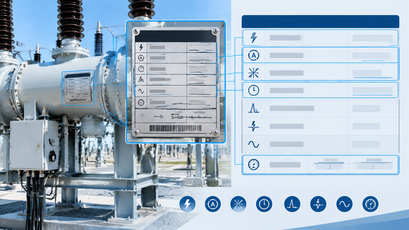
Annotated SF6 circuit breaker nameplate and specification sheet highlighting rated voltage, continuous current, breaking capacity, short-time withstand current and insulation level fields
Worked Example — Selecting a Breaker for a 110 kV Substation
Putting the sequence together makes the arithmetic clear. Take an outdoor 110 kV substation with the following design inputs from the system study: highest system voltage 123 kV, maximum load current 2400 A, prospective fault current 32 kA, backup protection clearing time 2.5 s, and an overhead line connection in a lightning-prone area.
Design input
Required value
Selected rating
Highest system voltage 123 kV
Rated voltage ≥ 123 kV
126 kV
Maximum load current 2400 A
Continuous current ≥ 2640 A (10% margin)
3150 A
Prospective fault current 32 kA
Breaking capacity ≥ 38.4 kA (20% margin)
40 kA
Backup clearing time 2.5 s
Short-time withstand for ≥ 2.5 s at 32 kA
40 kA / 3 s
Overhead line, lightning exposure
Insulation level coordinated to the 126 kV class
Class-rated LI and PF withstand
Outdoor switchyard
Weather-exposed installation
3-pole outdoor, spring mechanism
Each of those outputs maps directly onto an available configuration: the 3150 A continuous rating, the 40 kA breaking capacity and the 40 kA/3 s withstand are the three variants discussed in Steps 2, 3 and 4 above, all within the same LW36-126 platform. That is the practical value of resolving the ratings in order — the result is a coherent specification rather than a collection of maximums, which is also how you avoid paying for a 50 kA breaker on a 32 kA network.
Common Selection Mistakes
Using nominal voltage instead of highest system voltage. It leaves the breaker without dielectric margin for overvoltage.
Specifying breaking capacity from memory rather than from a fault study. Fault levels change when the network is reinforced; the breaker will not.
Leaving the short-time withstand duration blank. A breaker that withstands 40 kA for 1 s is not equivalent to one rated for 3 s if your backup protection takes 2.5 s.
Confusing breaking capacity with making capacity. They are separate tests, and the peak making current is roughly 2.5 times higher.
Applying no ambient derating. A current rating quoted at reference ambient is optimistic inside a hot enclosure or on a tropical site.
Ignoring gas pressure monitoring requirements. Alarm and block thresholds are part of the selection, especially for unmanned installations and cold climates.
Over-specifying “for safety”. Excess breaking capacity raises cost without raising protection, and it can complicate coordination with downstream devices.
Conclusion
Selecting an SF6 circuit breaker comes down to resolving six ratings in sequence against six design inputs you already have: highest system voltage, maximum load current, prospective fault current, backup clearing time, insulation exposure, and site conditions. Work through them in order, apply the standard margins, and the specification writes itself. The two figures that most often go missing are the short-time withstand duration and the environmental derating — both are cheap to specify up front and expensive to discover after commissioning.
If you have a system study in hand and want the rating set confirmed against a specific model, the LW36-126 range covers the 126 kV class from 3150 A continuous current through 40 kA breaking and 40 kA/3 s withstand, with 40.5 kV and 72.5 kV options available for the lower voltage steps. Send us your fault level, load current and site conditions, and we will map them to a configuration and provide the type-test documentation behind each rating.
FAQ
What is the difference between rated short-circuit breaking current and short-time withstand current?
Breaking current is what the breaker can interrupt — the arc is extinguished and the circuit opens. Short-time withstand current is what the breaker can carry while staying closed for a defined duration. Both are tested, and both must exceed the prospective fault current, but they answer different questions.
How much margin should I add to the short-circuit breaking capacity?
Apply 20–30% above the calculated prospective fault current, then round up to the nearest standard rating step. A 32 kA study result leads to a 40 kA breaker; a 40 kA result leads to 50 kA.
Can I use a 40.5 kV breaker on a 35 kV system?
Yes — that is the correct match. Rated voltage is set against the highest system voltage of the equipment class, not the nominal operating voltage, so the breaker class sits one step above the nominal network level.
Does altitude affect SF6 circuit breaker selection?
Above 1000 m, reduced air density lowers the external insulation strength of the breaker. Either apply the manufacturer’s altitude correction or specify a reinforced external insulation design; the internal SF6 insulation is unaffected.
What is rated making capacity and why does it matter?
Making capacity is the peak current the breaker can withstand while closing onto an existing fault. It is higher than the breaking current — roughly 2.5 times it at 50 Hz — and it drives the mechanical strength of the contact assembly and busbar supports.
Which standard defines SF6 circuit breaker ratings?
IEC 62271-100 defines the ratings and type tests for high-voltage alternating-current circuit breakers, including rated voltage, continuous current, breaking capacity, short-time withstand and insulation level. IEEE C37 series standards cover the equivalent requirements for North American projects.
What gas pressure should an SF6 circuit breaker be specified at?
It depends on the design. A typical 40.5 kV outdoor breaker uses a 0.5 MPa rated pressure with an alarm threshold around 0.47 MPa and a minimum functional pressure of 0.15 MPa. Always specify the alarm and block thresholds alongside the rated pressure, because those are the values operators act on.
A buyer-focused walkthrough of SF6 circuit breaker standards: what IEC 62271-100 and IEEE C37.04/C37.09 require, how to read a type test certificate, and where suppliers cut corners.
SF6 circuit breaker testing explained in three tiers: type tests, factory routine tests and on-site commissioning tests, with gas quality limits, contact resistance values and test report checks.
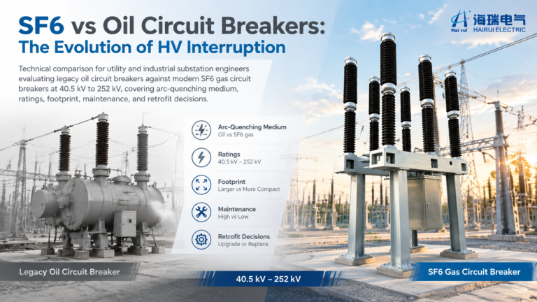
SF6 vs oil circuit breaker comparison: arc-quenching principles, bulk oil vs minimum oil, ratings, maintenance, fire risk, and a practical checklist for replacing legacy oil breakers with SF6 units.