Live Tank vs Dead Tank SF6 Circuit Breakers: Which Configuration Fits Your Grid?
Published: Author: Lisa
The live tank vs dead tank circuit breaker decision is usually presented as a matter of supplier preference. It is not. It changes where the current transformers live, how tall the structure is, how much the whole bay costs once CTs are included, and what a maintenance crew has to do fifteen years from now.
This guide compares the two configurations on the dimensions that actually decide projects: construction, CT integration, cost structure, footprint, seismic behaviour, maintenance access, and the voltage ranges where each one dominates. It applies to the outdoor HV equipment in the SF6 circuit breaker range, where a 40.5 kV porcelain-column unit and a 252 kV split-type unit illustrate the two ends of the same decision.
What “tank” actually refers to
Both configurations interrupt current inside SF6. The difference is where the interrupter sits relative to earth.
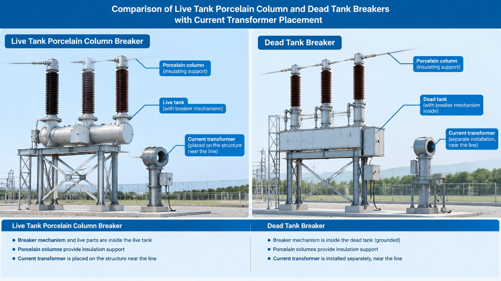
In a live tank breaker, the interrupter is inside an insulating column at line potential. The metal parts of the interrupter are alive; the porcelain or composite column holds them up and insulates them from the base.
In a dead tank breaker, the interrupter is inside a metal tank bonded to earth. The tank is dead — at earth potential — and the circuit is brought in and out through bushings on top.
Everything else follows from that single geometric fact. A live tank has no earthed enclosure around the interrupter, so it cannot house current transformers. A dead tank does, so the bushings become the natural place to put them.
Live tank construction
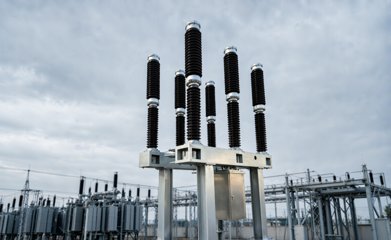
A live tank pole consists of a base frame, an insulating column, an interrupter head, and terminal pads. Three poles stand side by side, each with its own column — the arrangement often called split-phase or split-type.
Key properties:
One interrupter per pole at distribution and sub-transmission voltages, two in series at 252 kV.
Small gas volume per pole, in the range of a few kilograms — which makes gas handling cheap and leak consequences small.
No earthed enclosure, so the design is light: a 72.5 kV pole can be lifted by a small crane and assembled on site.
External insulation is the porcelain column, which is also the mechanical support, so creepage and mechanical strength are designed together.
Current transformers must be separate — stand-alone CTs on either side of the breaker, with their own footprint, oil or gas, and cost.
The construction is inexpensive to build and cheap to transport. A 72.5 kV porcelain column unit rated 4,000 A is a good example of the form at its most efficient: high continuous current, long creepage in a compact column, no tank to fabricate.
Dead tank construction
A dead tank pole is a cylindrical steel tank with bushings on top and the interrupter inside. The tank is bonded to earth and stands on a frame or directly on foundations.
Key properties:
Earthed metal enclosure, which is safe to touch and can carry the full fault current as a return path.
Bushing current transformers — toroidal cores mounted around the bushings inside the tank, giving multiple protection and metering cores with high ratios at almost no extra footprint.
Large gas volume, often tens of kilograms per pole, which means more gas to handle at commissioning and more to recover at end of life.
Low profile — the tank sits at or near ground level, so the centre of gravity is low and the bushings are short.
Heavier and larger — transport becomes a project in itself above 252 kV.
A 252 kV, 50 kA split-type outdoor breaker shows how the configuration scales: two interrupters per pole, separate poles for transport and assembly, and an external insulation design that has to satisfy both the switching duty and the site’s creepage requirement.
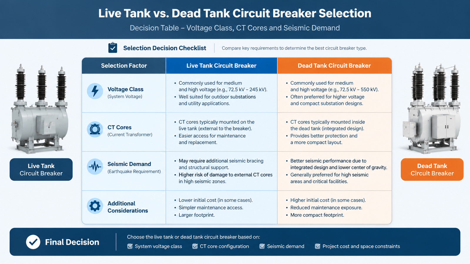
Side-by-side comparison
Dimension
Live tank
Dead tank
Interrupter location
At line potential, in insulating column
Inside earthed metal tank
Current transformers
Separate stand-alone CTs
Integral bushing CTs, multiple cores
Typical bay footprint
Compact for the breaker; CTs add space
Larger breaker, but CTs included
Height / centre of gravity
Tall, high CoG
Low, wide base
Gas volume per pole
Small (a few kg at 40.5–126 kV)
Large (tens of kg at 252 kV+)
Transport
Poles shipped separately, assembled on site
Larger units, heavier lifts
Seismic behaviour
Column acts as cantilever, needs base reinforcement
Better inherent stability
Internal maintenance access
Head can be lowered or accessed from platform
Requires tank entry with gas recovery
Relative equipment cost
Lower
Higher
Dominant regions
China, Europe, India, most of Asia
North America, high-seismic zones
Current transformers: the hidden cost driver
This is where the comparison is usually decided, and where simple equipment-price comparisons go wrong.
A live tank breaker needs its CTs as separate devices. At 40.5 kV and 72.5 kV, a stand-alone CT is cheap and compact, so the total bay cost stays low and the live tank wins comfortably. At 252 kV, a stand-alone CT is a large oil-filled or SF6-filled device with its own foundations, its own gas or oil inventory, and its own maintenance — and a bay may need three or four cores per phase for distance protection, backup protection, metering, and breaker failure.
A dead tank breaker puts those cores inside the tank, around the bushings. Four cores cost about the same footprint as one, the ratios are easy to change at the design stage, and there is no separate CT to align, earth, or maintain. Above roughly 145 kV, with three or more cores per phase, the integral arrangement frequently closes the price gap entirely — which is why dead tank dominates North American transmission practice despite its higher breaker price.
The correct comparison is bay-level, not breaker-level: breaker plus CTs plus foundations plus erection plus the space between them.
Where each configuration wins by voltage class
Voltage class
Common practice
Why
12–40.5 kV
Live tank, or metal-clad switchgear
Compact, cheap, separate CTs are small and inexpensive
72.5–145 kV
Live tank dominant
Best cost per bay; CTs still affordable as separate units
252 kV
Both, decided per project
CT core count and seismic requirement tip the balance
362–550 kV
Dead tank or GIS
Integral CTs, low profile, transport and seismic limits on live tank
800 kV
Dead tank or GIS
Live tank columns become impractical
The pattern is not about technical capability — both configurations interrupt the same fault currents to the same standard. It is about which cost dominates at each voltage. Low voltage: fabrication cost dominates, so live tank wins. High voltage: CT and structure cost dominate, so dead tank wins.
Our guide to SF6 circuit breaker types covers how puffer, self-blast, and double-pressure interrupters map onto these two enclosure arrangements.
Seismic, footprint and site conditions
Seismic behaviour
A live tank pole is a tall cantilever: the porcelain column carries the interrupter head at the top, and an earthquake loads it in bending. The design response is a reinforced base frame, a wider foundation, and sometimes damping or guy arrangements. Above a certain seismic level, the column itself becomes the limiting component, because porcelain is strong in compression and weak in bending.
A dead tank sits low and wide. Its mass is near the ground, its bushings are short, and the tank is a stiff steel cylinder. For sites with high seismic demand — parts of North America, Japan, Turkey, Chile — this is often the deciding argument, independent of cost.
Footprint
Live tank breakers are individually compact but need separate CT space, and the bay layout has to accommodate phase spacing driven by external clearances. Dead tank breakers occupy more area per unit but include the CTs within that area.
The net result varies with voltage and layout. At 40.5–126 kV, live tank bays are usually smaller overall. At 252 kV with multiple CT cores, dead tank bays can be comparable or even smaller once the separate CT foundations are counted. Bay layout logic is covered in SF6 circuit breakers in substations.
Climate and pollution
Both configurations are outdoors and both need creepage designed for the site. The live tank has an advantage in that its external insulation is a simple porcelain column, easy to specify at long creepage; the dead tank’s bushings are shorter and the shed profile has to do more work per unit length. In heavy pollution, this can push a dead tank design toward larger bushings or a higher creepage class.
Maintenance and lifecycle
The two configurations age differently, and the difference shows up in the maintenance plan rather than in the failure rate.
Gas work. A live tank pole holds a few kilograms, so recovery and refill are quick and a leak affects one phase. A dead tank at 252 kV holds tens of kilograms and often a single large compartment, so any internal work is a major gas handling job.
Internal access. Live tank interrupters can often be reached by lowering the head or working from a platform. Dead tank internal inspection requires tank entry, gas recovery, and usually a crane.
CT maintenance. Separate CTs add devices to maintain but keep them accessible. Integral bushing CTs are maintenance-free until the tank is opened, at which point they become part of a much larger job.
Mechanical endurance. This is a property of the mechanism, not the tank. A 3,000-operation mechanical life applies equally to either enclosure, and the choice should be made on operating duty rather than on configuration.
The lifecycle conclusion is simple: live tank is cheaper to maintain per intervention but needs more interventions on CTs; dead tank needs fewer interventions but each one costs more.
Live tank puts the interrupter at line potential; dead tank puts it inside an earthed enclosure with bushing CTs.Voltage class, CT core count and seismic demand settle most of these decisions before cost is discussed.
Decision checklist
Work through these eight questions in order. The answer usually falls out before the last one.
Voltage class. Below 145 kV, live tank is the default unless another factor overrides it.
Number of CT cores per phase. Three or more at 252 kV favours dead tank on total bay cost.
Seismic demand. High demand favours dead tank on structural grounds.
Site footprint available. Tight sites often favour live tank at MV, dead tank at HV.
Pollution level. Heavy pollution favours the configuration with the easier creepage specification — usually live tank.
Maintenance capability. A crew without gas recovery equipment and crane access is better served by live tank.
Standard and regional practice. IEEE-oriented projects expect dead tank; IEC-oriented projects expect live tank. Deviating adds engineering review time.
Delivery. Live tank poles ship more easily and assemble faster on site, which matters on retrofit schedules.
For a 126 kV bay, the comparison is often settled by cost and delivery, and a 126 kV 40 kA live tank unit is the conventional answer. For a 252 kV bay with four protection cores and a high seismic requirement, the same logic points toward a tank-type design. Neither answer is universally right.
Conclusion
Live tank and dead tank are not competing technologies; they are two cost structures for the same function. Live tank minimises fabrication and transport, and pays for it with separate CTs and a tall cantilever structure. Dead tank minimises CT cost and structural height, and pays for it with a heavier, more expensive enclosure and larger gas volumes.
Compare at bay level, weight the CT cores and the seismic demand properly, and the choice becomes arithmetic rather than preference. If you are at 252 kV and unsure which way the numbers fall, send us your CT core schedule, seismic requirement, and site conditions — that is enough to size both options. For the wider picture, browse the SF6 circuit breaker library.
FAQ
What is the main difference in a live tank vs dead tank circuit breaker?
In a live tank breaker the interrupter sits at line potential inside an insulating column. In a dead tank breaker it sits inside an earthed metal tank, with the circuit connected through bushings. The tank’s potential — live or dead — is the defining difference.
Which type is better for high seismic areas?
Dead tank. Its mass is low and its base is wide, so earthquake loading produces less bending stress than in a tall porcelain column. Live tank installations in seismic zones need reinforced bases and sometimes modified column designs.
Why do dead tank breakers have built-in current transformers?
Because the bushings pass through the tank, toroidal CT cores can be mounted around them inside the enclosure. This gives multiple protection and metering cores without separate CT devices, which is a significant cost and footprint advantage at high voltage.
Can a live tank breaker have integral CTs?
Not in the same way. With no earthed enclosure around the interrupter, there is nowhere to mount bushing CTs, so current transformers must be separate stand-alone units on either side of the breaker.
Which is cheaper overall?
At 40.5–145 kV, live tank is usually cheaper at bay level. At 252 kV and above with three or more CT cores per phase, dead tank frequently becomes competitive or cheaper once the separate CT cost is included.
Is maintenance harder on a dead tank breaker?
Internal work is harder, because it requires gas recovery, tank entry, and lifting equipment. Routine maintenance is comparable. The trade-off is that a dead tank needs fewer interventions on current transformers, since they are sealed inside the tank.
Why a breaker rated 40 kA may still restrike on 50 A: the four capacitive duties, preferred current values by voltage class, C1 vs C2 tests and what to check.