SF6 vs Vacuum Circuit Breaker: Which One Is Better?
Vacuum or SF6? Compare arc quenching, voltage limits, switching behaviour, maintenance, F-gas rules and cost to pick the right circuit breaker for your network.
Read More
Every SF6 circuit breaker operating mechanism answers one hard question: how do you move a contact that weighs several kilograms across a 40 mm gap in under 25 milliseconds, using energy that was stored minutes or hours earlier? The interrupter gets the attention, but it is the mechanism that decides whether a breaker trips cleanly on a fault or welds itself shut. This guide breaks down the three mechanism families used in modern HV breakers — spring, pneumatic and hydraulic — walks through the full four-stage spring operating cycle, and shows you how to match mechanism type to voltage class, switching duty and maintenance reality.
The operating mechanism is the prime mover of the breaker. It performs four jobs, and a weakness in any one of them shows up as a protection failure rather than a mechanical annoyance:
That fourth job is where most field problems originate. A mechanism that is mechanically perfect but reports the wrong status to the relay will still cause a misoperation. If you want the wider context of how the interrupter and mechanism work together, start with what an SF6 circuit breaker is and how it is constructed.
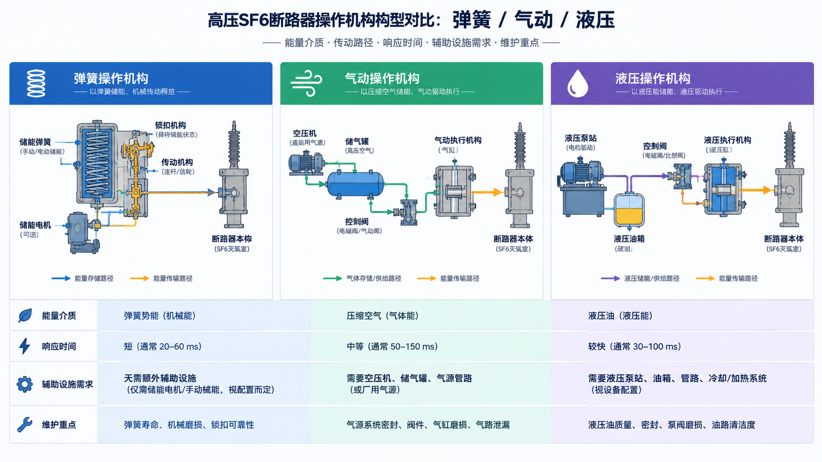
All three do the same job with a different energy medium. The differences that matter commercially are response time, auxiliary plant requirement, and how much maintenance the mechanism demands over a 20-year life.
| Characteristic | Spring mechanism | Pneumatic mechanism | Hydraulic mechanism |
|---|---|---|---|
| Energy medium | Helical compression springs | Compressed air in a receiver | Hydraulic oil in an accumulator |
| Typical opening time | 30–50 ms | 50–80 ms | 40–60 ms |
| Auxiliary plant | None beyond station DC | Air compressor, dryer, receiver | Oil pump, accumulator, nitrogen bladder |
| Maintenance focus | Lubrication and latch wear | Moisture removal, valves, seals | Fluid leaks, seal integrity, oil quality |
| Typical voltage range | 12 kV – 550 kV | 72.5 kV – 245 kV | 245 kV – 800 kV |
| Best suited to | Frequent switching, outdoor substations | High-speed reclose duty, legacy fleets | Very high breaking energy, UHV |
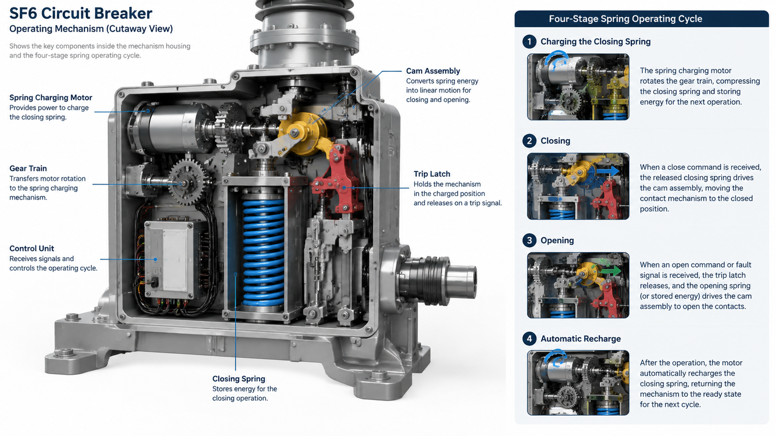
The spring mechanism dominates medium and high voltage breakers because it is self-contained. A geared motor compresses one or more helical springs through a ratchet and cam arrangement; a latch holds the compressed spring indefinitely; and a trip or close coil releases the latch on command. There is no compressor to run, no oil to sample, and no pressure to top up. A 72.5 kV outdoor breaker such as the LW9-72.5 with combined reclosing at 3150 A is a good example of the layout: the spring mechanism shares the mechanism housing with the gas density relay and the local control cabinet, so the whole operating system sits in one weatherproof enclosure.
The trade-off is stored energy. A spring can only hold what was wound into it, so designs are engineered around a defined duty cycle — normally a full O-CO-CO sequence without recharging. If a specification demands more consecutive operations than the spring can supply, you either accept a recharge delay or move up in voltage class to a different mechanism.
Pneumatic mechanisms use compressed air at roughly 1.5 to 3 MPa to drive a piston. Because air pressure can be replenished continuously from a compressor, they tolerate heavy duty cycles and were historically popular for high-speed reclosing on transmission lines. The cost is the auxiliary plant: compressor, dryer, receiver tank, pressure switches and safety valve all become part of the breaker’s maintenance scope. Air moisture is the persistent enemy, and in humid tropical installations the dryer becomes a critical asset rather than a convenience.
New pneumatic designs are now uncommon. Most pneumatic mechanisms in service are on legacy 72.5 kV to 245 kV fleets, where replacing the mechanism is usually less attractive than replacing the whole breaker.
Hydraulic mechanisms store energy in pressurised oil, usually backed by a nitrogen bladder inside the accumulator that acts as a gas spring. Hydraulic actuation produces very high output force from a compact package, which is why it is the default choice above 245 kV and inside gas-insulated switchgear where space is at a premium. A 252 kV split-type outdoor breaker needs the kind of energy density that only a hydraulic accumulator delivers comfortably.
The penalty is maintenance discipline. Hydraulic systems leak. Oil viscosity changes with temperature, so cold-climate installations need heater circuits and cold-grade fluid. Seal integrity, accumulator pre-charge pressure and oil cleanliness all become routine inspection items. When a hydraulic breaker develops a slow close, the cause is more often fluid-related than mechanical.
Almost every spring mechanism on the market follows the same four-stage sequence. Understanding it makes field troubleshooting far faster, because each stage has a distinct set of failure signatures.
The charging motor drives a reduction gearset and turns a charging shaft. A cam on that shaft compresses the closing spring until a pawl drops into the ratchet and locks it at the charged position. A limit switch then cuts the motor. Charging typically completes in 10 to 20 seconds on a medium voltage mechanism and can run to 20 seconds or more on larger HV units. Manual charging via a hand crank is always provided as a fallback for loss of DC supply.
On a close command, the closing coil is energised and pulls the closing latch out of engagement. The charged closing spring releases through the cam, converting rotational motion into linear travel of the operating rod that drives the moving contact into the closed position. Critically, the same stroke also charges the opening spring — so the breaker ends the close operation with a fresh store of energy for the next trip.
On a trip command, the trip coil releases the opening latch. The opening spring, already charged during the close stroke, drives the contacts apart. This is the fast half of the cycle: opening times of 25 to 50 ms are normal, and the contact speed in the first few millimetres is what stretches and cools the arc so the SF6 gas can extinguish it at the natural current zero.
Immediately after the close operation, the charging motor restarts automatically and recompresses the closing spring, restoring the breaker’s stored energy reserve. This stage is invisible in normal operation and is the single most overlooked part of the cycle. If the auto-recharge fails, the breaker will still trip — but it will not close again. In a substation where a reclose is expected after a transient fault, that failure turns a momentary outage into a sustained one.
Many utilities monitor recharge time as a predictive maintenance indicator: a charging time that creeps up by 20 % or more usually means a worn motor, a dry gearset or a weakening spring.
The interrupter and the mechanism are a matched pair, and the physics links them tightly. To extinguish an arc, the contacts must separate fast enough to build the required gas pressure and stretch the arc before the current crosses zero. In a self-blast design, the arc’s own energy heats the gas and raises the pressure, which reduces the mechanical energy the mechanism must supply — but the mechanism still has to deliver a minimum velocity curve.
This is why a mechanism swap is never a drop-in repair. Changing from one spring mechanism model to another with a different output travel or velocity profile changes the breaker’s opening time, its dielectric recovery margin, and ultimately its type-test validity. If your SF6 breaker uses a self-blast interrupter, the mechanism requirement is lighter than for an older puffer design — one more reason the different SF6 interrupter types matter when you are comparing mechanism specifications.
Use the matrix below as a first-pass filter when specifying a new breaker or evaluating a replacement. Voltage class sets the floor; switching duty sets the final choice.
| Application | Voltage class | Recommended mechanism | Why |
|---|---|---|---|
| Distribution feeder, capacitor bank | 12 kV – 40.5 kV | Spring | Frequent switching, minimal auxiliary plant, indoor or outdoor |
| Substation incomer, transformer bay | 72.5 kV – 126 kV | Spring (or pneumatic on legacy fleets) | Reclosing duty handled by spring with adequate recharge margin |
| Transmission line, high-speed reclose | 126 kV – 252 kV | Hydraulic or heavy-duty spring | Repeated O-CO-CO sequences demand large stored energy |
| UHV substation, GIS | 252 kV – 800 kV | Hydraulic | Highest output force per unit volume, compact mechanism bay |
| Cold climate, remote site | Any | Spring | No compressed air moisture risk, no oil viscosity shift |
For 72.5 kV class work, the LW9-72.5 family shows how the same mechanism platform scales with breaking duty: the 4000 A high breaking capacity version carries a heavier moving contact assembly than the standard 3150 A unit, and the 350 kV lightning impulse withstand variant is specified where external insulation margin, not mechanism energy, is the binding constraint.
The mechanism only performs correctly if the control circuit around it is correct. Three features deserve attention during commissioning:
As a rule, every intact mechanism should be able to complete at least one full open-close-open cycle from a single stored-energy charge. Verify this during commissioning by measuring the operation sequence with the charging motor supply isolated.
Most mechanism faults present as one of five symptoms. The table below maps them to the likely cause and the first check to make.
| Symptom | Likely cause | First check |
|---|---|---|
| Charging motor runs but spring never indicates charged | Worn ratchet or pawl, slipping free-wheel, limit switch misadjusted | Manual charge to confirm the mechanism can reach the latched position |
| Breaker will not close on command | Closing coil open circuit, latch not releasing, low stored energy lockout active | Coil resistance and supply voltage at the coil terminals |
| Slow opening or closing time drift | Mechanical binding, degraded lubricant, weakened spring, hydraulic fluid issue | Compare measured travel time against nameplate, tolerance ±10 % |
| No automatic recharge after closing | Motor supply lost, limit switch stuck, motor thermal protection tripped | Motor supply and control circuit continuity |
| Repeated trip-close cycling (pumping) | Anti-pumping interlock defective or missing, close contact stuck | Anti-pumping relay and close circuit wiring |
Two habits prevent most of these faults: apply the manufacturer-specified low-temperature grease to latches and linkages on schedule, and log charging time and contact travel time at every inspection. Trend data catches a degrading mechanism long before it fails to operate.
Mechanism specification is where buyers most often under-specify, because the mechanism is buried inside the breaker’s technical data rather than highlighted on a datasheet. When you issue an enquiry, ask for these five items explicitly:
Also confirm the auxiliary contact configuration and whether the mechanism includes heater circuits for the control cabinet. On an outdoor installation in a humid climate, a missing cabinet heater is a far more common cause of nuisance failures than any mechanism defect.
If you are comparing an SF6 breaker against alternatives, the gas itself shapes the mechanism requirement — SF6’s arc-quenching behaviour is roughly two orders of magnitude better than air, which is why a comparatively light mechanism can handle very high breaking currents. That relationship is worth understanding before you finalise a specification: why SF6 gas is used in circuit breakers explains the physics behind the mechanism sizing rules.
The operating mechanism is a stored-energy problem. Spring mechanisms win on simplicity and suit most 12 kV to 126 kV applications; pneumatic mechanisms survive mainly on legacy fleets where continuous air supply justified the auxiliary plant; hydraulic mechanisms remain the only practical answer above 245 kV and in GIS. Whatever the type, the four things that decide long-term reliability are identical: correct stored energy for the duty cycle, clean lubrication, a functioning anti-pumping interlock, and an automatic recharge that actually completes. Verify those four at commissioning and monitor them by trend, and the mechanism will not be the part that lets you down.
If you are specifying a breaker for a substation, feeder or transmission bay, you can review the full range of high voltage SF6 circuit breakers by voltage class and mechanism configuration, or send your duty cycle and station DC voltage for a mechanism recommendation.
The spring operating mechanism is by far the most common, covering most 12 kV to 126 kV breakers and a large share of 252 kV units. It needs no compressor or hydraulic pump, stores energy independently of station auxiliary supply, and is the simplest to maintain. Pneumatic mechanisms are now largely confined to older transmission fleets, while hydraulic mechanisms dominate above 245 kV and inside GIS.
A spring-spring mechanism uses two separate springs: the closing spring stores energy for the close operation, and the opening spring is charged during the close stroke to provide energy for the trip. This arrangement means a fully charged breaker can complete an open-close-open sequence without recharging, which is the standard requirement for a mechanism to be considered intact.
Typical charging times range from about 10 to 20 seconds for medium voltage mechanisms and up to roughly 20 seconds or more for larger high voltage units. Charging time is a useful condition indicator: if it increases by more than about 20 % from the commissioning baseline, inspect the charging motor, gearset and spring for wear.
It can complete one stored-energy operation sequence. Spring, pneumatic and hydraulic mechanisms all store energy mechanically or pneumatically, so the breaker can still trip on a protection command after station DC or AC supply is lost, provided the stored energy is above the lockout threshold. After that single sequence, recharging requires power or manual cranking.
The most common cause is a failure of the automatic recharge stage after the previous close operation, which leaves the closing spring discharged. Other frequent causes are a defective closing coil, a latch that has not fully released, a low stored-energy lockout that is still active, or a reclose blocking contact incorrectly wired into the protection scheme.
No. The mechanism itself does not need nitrogen. Nitrogen appears in some hydraulic mechanisms only as a sealed pre-charge inside the accumulator bladder, where it acts as a gas spring. It never enters the mechanical linkage, and it is unrelated to the SF6 gas used in the interrupter for insulation and arc quenching.