Where Are SF6 Circuit Breakers Used? 7 Key Applications
Published: Author: Lisa
The short answer to where SF6 circuit breakers are used is: anywhere high voltage has to be switched, protected or isolated under fault current. That covers transmission substations, distribution feeders, power stations, renewable collector networks, railway traction supply, heavy industrial plants and remote mining sites. What changes between them is the duty cycle, the fault level and the environment — not the basic reason the breaker exists.
This guide works through seven application families, showing the voltage class, the typical rating and the specific reason an SF6 circuit breaker is chosen over the alternatives in each case. If you are sizing a unit for one of these duties, the application profile matters more than the headline voltage: a 126 kV breaker protecting a wind farm collector sees a very different life from a 126 kV breaker at a grid node with auto-reclosing enabled.
Quick Answer: The Seven Application Families
The table below is the whole article in one view. Each row is expanded in the sections that follow.
Application
Typical voltage
Typical rating
Defining duty
Why SF6
Transmission substations
72.5 – 550 kV
2000 – 4000 A, 40 – 63 kA
Line faults, auto-reclosing, system stability
High breaking capacity in a compact outdoor envelope
Distribution substations
12 – 40.5 kV
630 – 2000 A, 20 – 31.5 kA
Frequent feeder switching, capacitor banks
Compact sealed units, low maintenance outdoors
Power plants
12 – 252 kV
3150 – 6300 A, 40 – 63 kA
Generator and station-service protection
High continuous current with high fault level
Renewable collector substations
33 – 145 kV
1250 – 3150 A, 25 – 40 kA
Frequent switching, wide ambient range
Outdoor reliability with low maintenance access
Railway traction supply
25 – 220 kV
1250 – 3150 A, 25 – 40 kA
High switching frequency, single-phase loads
Long mechanical life under repeated operation
Heavy industry
35 – 145 kV
1250 – 3150 A, 25 – 40 kA
Arc furnace, motor starting, captive generation
Tolerant of harmonic-rich and repetitive duty
Mining and remote sites
33 – 145 kV
1250 – 2500 A, 25 – 40 kA
Dust, altitude, temperature extremes
Sealed design, infrequent maintenance visits
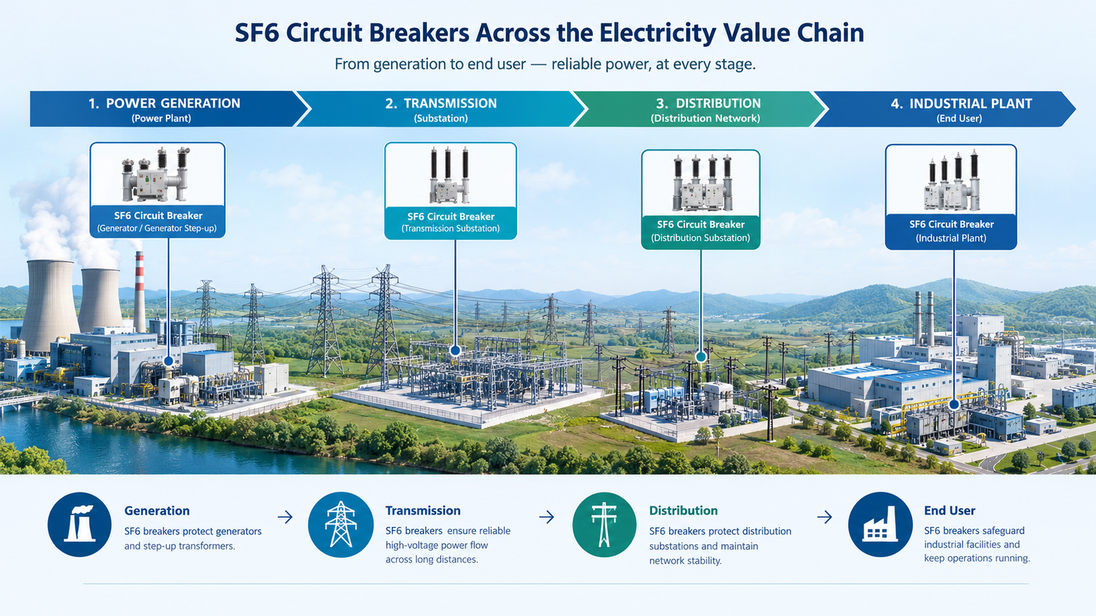
Where SF6 breakers sit across the electricity value chain.
1. Transmission Substations
This is the application most people picture: outdoor live-tank or dead-tank breakers on a steel structure, one per line bay, connected through disconnectors and current transformers. The duty is severe. A transmission breaker must interrupt full fault current at the system’s maximum short-circuit level, reclose automatically onto a transient fault within a few hundred milliseconds, and then do it again if the fault persists.
SF6 dominates here for a structural reason rather than a commercial one. A 252 kV breaker has to hold off a lightning impulse level around 1050 kV while fitting within a footprint that substation designers can afford. Gas insulation makes that possible at a size that civil works can support. Typical units in this class are split-type outdoor designs with 4000 A continuous current and 50 kA breaking capacity, such as the LW-252 252 kV 4000 A split-type breaker. The bay layout, protection scheme and breaker-and-a-half arrangements are covered in our guide to SF6 circuit breakers in substations.
One practical point for buyers: transmission breakers are usually specified with combined reclosing capability, meaning the mechanism and control scheme support single-phase and three-phase reclose sequences. That is a different mechanical duty from a unit that only ever opens on command, and it should be written into the specification rather than assumed.
2. Distribution Substations and MV Feeders
At 12 kV to 40.5 kV the application changes character. Fault levels are lower, switching frequency is far higher, and the equipment often sits in an unattended outdoor enclosure or a pole-mounted installation where maintenance visits are expensive. A distribution breaker may operate several times a day for load transfer and capacitor bank switching, then sit idle for months.
This is the segment where vacuum has taken the most ground, and rightly so. SF6 remains common in outdoor pole-mounted and compact sealed designs where a single gas-filled tank provides both insulation and interruption with very few moving parts — the LW8-40.5 2000 A unit with 95 kV power-frequency insulation is a representative example of that configuration. Where the substation is indoors and the switchboard is being replaced anyway, vacuum with air or solid insulation usually wins on total cost. The installation-format trade-off is set out in our comparison of indoor and outdoor SF6 circuit breakers.
3. Power Plants
Power stations use breakers in three distinct roles, and they are often confused. The generator circuit breaker sits between the generator terminals and the step-up transformer and must carry the generator’s full rated current — frequently 6300 A or more — while interrupting a fault fed by both the generator and the grid. Station-service breakers protect the auxiliary supply that runs pumps, fans and control systems. Unit and line breakers connect the plant to the network.
The generator application is the demanding one. Continuous current is high, the fault current has a large DC component from the generator, and the breaker is expected to operate only rarely but with complete certainty. SF6 handles the current-carrying requirement in a smaller envelope than air-blast or vacuum at these ratings, which is why it remains standard in large thermal and hydro stations. For smaller plants and renewable installations, the same function is often served at 126 kV by a conventional line breaker, as discussed in the next section.
4. Renewable Collector Substations
Wind and solar farms aggregate dozens of generators onto a collector network that steps up to 33 kV, 72.5 kV or 126 kV before connecting to the grid. The breaker duty here is unusual in two ways. First, switching frequency is high: wind farms switch feeders as wind conditions change, and solar plants switch inverters and capacitor banks daily. Second, ambient conditions are often extreme — coastal salt spray, desert heat, high altitude — and maintenance access is poor.
That combination favours sealed outdoor gas designs with long mechanical life and infrequent inspection. Combined reclosing capability is also useful where the collector network is radial and a transient fault on one feeder should not take out the whole farm. Units such as the LW9-72.5 with combined reclosing and 3150 A rating fit that duty profile at the 72.5 kV level. Grid codes in most markets also require the breaker to withstand voltage dips and rapid reconnection, which pushes specifications toward tested type-test evidence rather than generic ratings.
5. Railway Traction Power Supply
Electrified railways draw power through traction substations that step the grid supply down to 25 kV, 2×25 kV or 15 kV single-phase for the overhead catenary. Breakers in this application operate far more often than grid breakers — every time a train enters a section, a fault occurs, or the feeding arrangement is reconfigured. Mechanical endurance, not breaking capacity, is usually the binding constraint.
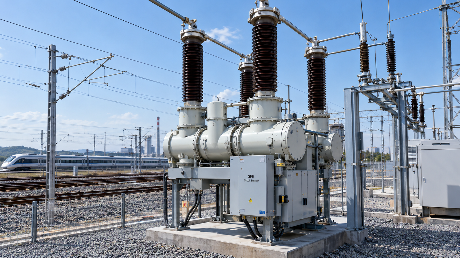
An SF6 breaker on the incoming side of a railway traction substation.
Traction duty also brings asymmetric loads, harmonic content and frequent short interruptions. SF6 breakers at 126 kV or 72.5 kV are commonly used on the incoming side of traction substations, while the 25 kV catenary side is usually vacuum or SF6 depending on the operator’s standard. A 126 kV unit with 3150 A continuous current and 40 kA breaking capacity, such as the LW36-126 126 kV 3150 A breaker, is a typical incoming feeder specification for a main-line traction substation. Where the railway runs through tunnels or dense urban areas, indoor metal-clad arrangements are used instead and the technology choice shifts toward vacuum.
6. Heavy Industry
Steel mills, cement plants, chemical complexes and large manufacturing sites usually operate a captive high-voltage substation fed from the utility grid. The breaker at the point of supply protects the plant transformer and the internal distribution network. Inside the plant, SF6 or vacuum breakers feed arc furnaces, large motors and compressor trains.
Two duties make this application distinctive. Arc furnaces produce rapidly fluctuating loads with strong harmonic content, which stresses the breaker’s thermal design and the current transformers around it. Large motor starting produces repeated high inrush currents. Neither is beyond the capability of a properly specified breaker, but both argue against cutting margins on continuous current or mechanical life. Industrial buyers also tend to value standardisation: one breaker type across several plants simplifies spares and training, which often outweighs a small price difference per unit.
7. Mining and Remote Sites
Mine sites, oil and gas facilities, and island or off-grid networks share a common constraint: skilled maintenance is far away. A breaker that needs a gas top-up every year is a logistical problem when the nearest service depot is a flight away. Sealed-for-life SF6 designs with a documented low leak rate and a long mechanical life are the practical answer, even where a vacuum alternative would be cheaper at the point of purchase.
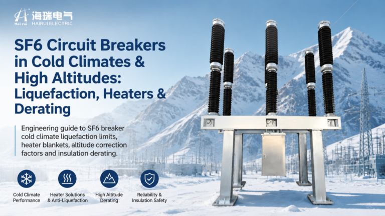
Environmental conditions drive the specification more than electrical ratings. Altitude above 1000 m requires external insulation correction. Ambient temperatures beyond −25 °C to +40 °C affect gas density and mechanism lubrication. Dust and humidity demand IP-rated enclosures and, in coastal or chemical environments, corrosion-resistant hardware. These are all standard options, but they must be stated at enquiry stage rather than discovered during commissioning.
What the Applications Have in Common
Strip away the sector labels and three variables determine whether SF6 is the right choice: fault level, switching frequency and maintenance access. The table below shows how those three interact.
Duty profile
Fault level
Switching frequency
Maintenance access
Best fit
Grid transmission node
Very high
Low, with reclosing
Good
SF6, high breaking capacity
Urban distribution
Moderate
Moderate
Good
Vacuum or solid dielectric
Renewable collector
Moderate
High
Poor
Sealed SF6 or clean air
Railway traction
Moderate
Very high
Moderate
SF6 with high mechanical endurance
Remote mine or island
Moderate to high
Low
Very poor
Sealed SF6, low leak rate
Where fault level is high and access is good, SF6 earns its place on breaking capacity per cubic metre. Where switching frequency is high and access is good, vacuum usually wins on mechanical life and simplicity. Where access is poor, sealing quality matters more than either, because every maintenance visit is a cost and a risk. The technology comparison behind those judgements is set out in our analysis of SF6 versus vacuum circuit breakers, and the voltage ladder itself is explained in the guide to SF6 circuit breaker voltage classes.
Matching the Breaker to the Application
Before issuing an enquiry, write down five numbers and two conditions. The numbers are system nominal voltage, maximum operating voltage, continuous current, short-circuit breaking current and short-time withstand duration. The conditions are the expected number of operations per year and the site’s ambient and altitude envelope. Almost every mis-specified breaker traces back to one of those seven items being left to the supplier to guess.
Then add the application-specific items that are easy to forget:
Reclosing requirement and the sequence (single-phase, three-phase, or both).
Whether the unit will switch capacitor banks or unloaded cables, which brings restrike performance into scope.
Whether generator or motor inrush will be seen, and at what magnitude.
Seismic requirement, which varies sharply between regions.
Communication and control protocol expected by the protection scheme.
Gas recovery and reporting obligations if the project has an environmental lender.
Conclusion
SF6 circuit breakers appear in seven broad application families, and in each one they are chosen for a specific combination of breaking capacity, compactness and sealing quality. Transmission and generator duties need high breaking capacity in a small envelope. Distribution needs low maintenance outdoors. Renewables, traction and remote sites need mechanical endurance and sealed-for-life construction more than they need headline fault ratings. Getting the application profile right at specification stage is what separates a breaker that runs for thirty years from one that becomes a maintenance item in five.
If you are specifying breakers for any of these duties, tell us the application, voltage class and fault level. Our engineering team can match the configuration — live-tank, dead-tank, split-type or compact sealed — and supply the type-test documentation your project owner will ask for. The full range starts from the high voltage SF6 circuit breaker category.
FAQ
What is the most common application of an SF6 circuit breaker?
Transmission and sub-transmission substations between 72.5 kV and 252 kV, where high breaking capacity is needed in an outdoor footprint that civil works can support. Distribution applications at 12 kV to 40.5 kV are the second largest and are increasingly served by vacuum instead.
Are SF6 breakers used in wind and solar farms?
Yes. Renewable collector substations typically use SF6 breakers at 33 kV, 72.5 kV or 126 kV on the grid-side connection, because sealed outdoor designs tolerate remote locations and high switching frequency with infrequent maintenance.
Why do railway traction substations use SF6 breakers?
Mainly for mechanical endurance. Traction breakers operate far more often than grid breakers, so long mechanical life and reliable sealing matter more than maximum breaking capacity. They are usually installed on the incoming 72.5 kV or 126 kV side.
Can vacuum breakers replace SF6 in every application?
No. Vacuum is the better choice below 40.5 kV indoors, but above 72.5 kV outdoors the dielectric requirement pushes vacuum designs to larger, heavier and more expensive configurations than SF6 for equivalent ratings.
What voltage do industrial plants use SF6 breakers at?
Most commonly 35 kV to 145 kV at the point of supply from the utility, protecting the plant’s main transformer. Internal distribution below 35 kV is usually vacuum or air-break.
How often do SF6 breakers need maintenance in remote sites?
Sealed-for-life designs with a leak rate below 0.1% per year typically need inspection at five-year intervals and no gas top-up across the design life. Older or non-sealed designs require annual gas density checks.
Why a breaker rated 40 kA may still restrike on 50 A: the four capacitive duties, preferred current values by voltage class, C1 vs C2 tests and what to check.