SF6 Circuit Breaker Failure & Troubleshooting: Common Causes
Published: Author: Lisa
An SF6 circuit breaker failure rarely announces itself. Most of the time the first indication is a breaker that will not close when the operator asks, or a low-gas alarm that appeared at 2 a.m., or a trip that never happened and a feeder that stayed live into a fault. The troubleshooting skill that matters is not knowing every possible fault — it is knowing which family of fault you are in within the first ten minutes.
This guide works through the failure modes of outdoor high-voltage SF6 breakers from 40.5 kV to 252 kV, the class represented by the high voltage SF6 circuit breakers range. It is written for the engineer standing at the control cabinet with a multimeter, not for the design office. Safety comes first throughout: nothing in this article overrides your switching authority’s procedures.
How SF6 Breaker Failures Present Themselves
Almost every SF6 breaker fault shows up as one of five observable symptoms. Identifying the symptom correctly is half the diagnosis, because each symptom narrows the fault family immediately.
Symptom
What the operator sees
Most likely families
Will not trip
Close works, open command produces nothing or a partial operation
Control circuit, trip coil, latch, density lockout
Will not close
Open works, close command rejected or spring does not recharge
Spring/motor, close coil, interlock, synchrocheck
Trips without command
Unexplained trip, often with no protection flag
DC earth fault, vibration, auxiliary contact, EMI
Gas alarm or lockout
Low density alarm, then lockout, breaker blocked
Leak, seal, density relay, gauge
Overheating or flashover
Hot terminal, discolouration, tracking, audible discharge
Two of these five — gas alarms and overheating — are progressive and give warning. The other three are binary and appear without notice, which is why they dominate unplanned outages.
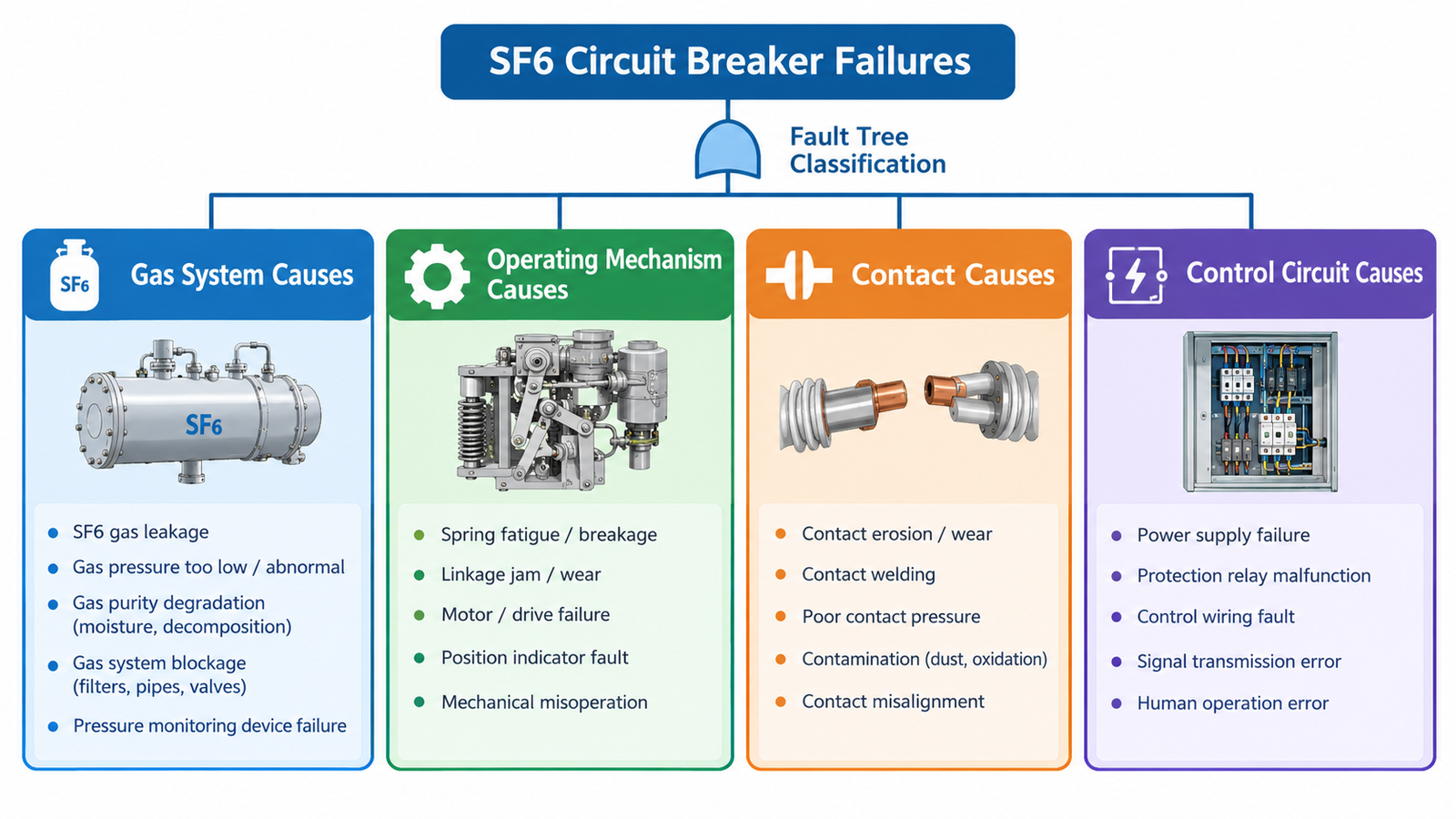
The Four Failure Families
Every fault belongs to one of four subsystems. Sorting the symptom into a family is the fastest way to stop guessing.
Four families cover almost every failure: gas, mechanism, contacts and control.
Family
Typical causes
Share of failures
Gas system
Seal leaks, gauge root leaks, burst disc seepage, moisture ingress, density relay drift
Common, usually slow
Operating mechanism
Spring fatigue, damper wear, latch wear, motor failure, lubrication loss, linkage wear
DC supply loss, coil open circuit, wiring termination, auxiliary contact, interlock, EMI
Most frequent cause of “breaker won’t move”
The distribution matters. In practice, a breaker that refuses to operate is far more likely to have a control or mechanism problem than an interrupter problem — which is why the first test is always electrical, not mechanical.
Failure to Trip
A breaker that will not trip is the most dangerous failure in the list, because the backup is breaker-failure protection tripping the surrounding bays. Work through it in this order.
Confirm the command arrived. Check the protection relay trip flag and the event log. If there is no flag, the problem is upstream of the breaker and you are troubleshooting the wrong device.
Check DC supply at the trip coil terminals. Measure during the trip attempt, not before it. A supply that reads 220 V at rest and collapses under trip current points to a battery, charger or wiring problem, not a coil problem.
Measure trip coil resistance. Compare against the commissioning value. An open circuit is a failed coil; a large increase is a partially failed coil or a bad termination.
Confirm no lockout is active. Low gas density lockout blocks trip commands on many designs. If the density relay is in lockout, the breaker is behaving correctly and the fault is gas, not control.
Test the mechanism locally. A local manual or local electrical trip that works while a remote trip does not isolates the fault to the remote circuit, cabling or interposing relays.
Only then consider the mechanism. Latch wear, a sticking trip linkage or a damper that has seized will produce a partial or slow operation rather than nothing at all — if you see a slow operation, the mechanism is the answer.
One recurring case deserves its own line: the breaker that trips correctly on a local test but not from the relay. That is almost always an interposing relay, a wiring termination, a fuse in the trip circuit, or a protection output card — never the breaker. Test the whole trip path, from relay output to coil, and record the result.
Failure to Close
Closing failures are usually more benign but equally disruptive, because a bay that cannot be restored delays everything downstream.
Spring not charged. Check the charge indicator and the motor supply. A spring mechanism that has lost its charge cannot close regardless of commands. Listen for the motor: silence after a close operation means the recharge circuit failed.
Motor protection tripped. Most spring mechanisms have a motor protection relay or MCB. A tripped device points to a mechanical resistance problem — dry bearings, a failing motor or a misaligned limit switch.
Close coil open circuit. Measure resistance as for the trip coil.
Interlock holding. Earthing switch closed, disconnector not in the correct position, or a spring-charge interlock not made. Read the interlock status on the cabinet rather than assuming.
Synchrocheck or close-block from protection. A close command that is refused with no mechanical symptom is frequently a protection-level block, not a breaker fault. Check the relay event log.
Anti-pumping active. If a close command is held on continuously, anti-pumping logic will prevent a second close. Release the command and retry once.
The distinction to keep in mind: a close failure with a healthy motor and a charged spring is almost always electrical or interlock. A close failure with an uncharged spring is almost always mechanical.
Low Gas Density Alarm and Lockout
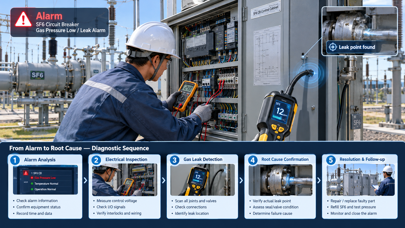
The density relay is the breaker’s own protection against itself, and it produces more nuisance investigations than any other device on the unit.
First, verify the reading. Density relays drift and gauges fail. Cross-check with a calibrated pressure gauge and apply the temperature correction from the manual. A reading taken at 5 °C in the morning and one taken at 35 °C in the afternoon are not comparable unless corrected. A genuine low-density condition will be confirmed by both the relay and the corrected gauge reading.
Second, distinguish alarm from lockout. The alarm stage typically sits a few percent below rated density; the lockout stage sits below that. If the breaker is in lockout, it will refuse to operate — and that refusal is correct behaviour, not a fault to be bypassed. Never defeat a density lockout to restore service.
Third, localise the leak. The common leak points on an outdoor SF6 breaker are predictable: the density relay and gauge roots, flange gaskets between interrupter and support column, the burst disc, the operating rod seal at the mechanism entry, welded seams on the tank, and the sealing washers on any test or filling valve. A leak survey with a portable detector around these points will find the majority within an hour.
Fourth, quantify it. If the detector is inconclusive, bag the suspect joint and measure the concentration build-up over a known interval. A quantitative leak rate tells you whether you can defer the repair to the next planned outage or must act now.
One case looks like a leak but is not: a breaker that alarms in cold weather and recovers by afternoon. That is a density relay set too close to the operating point, or a gauge that is not temperature compensated. It still needs correction, but it is a relay problem rather than a gas problem.
Gas Leak Diagnosis in Practice
Three methods cover nearly every situation, and they are complementary rather than alternatives.
Method
Best for
Limitation
Portable sniffer detector
Localising an active leak on accessible joints
Wind disperses gas; needs slow, close passes
Bagging and concentration build-up
Quantifying a suspected joint leak
Requires the joint to be baggable and time on site
Ultrasonic detection
Very small leaks and pressurised compartments
Background noise in live substations
Whatever method you use, record the date, the compartment, the density before and after any top-up, and the quantity added. Without those records, the next engineer inherits no history and starts from zero.
Contact and Insulation Failures
These are the failures with the highest consequence, because they end in flashover or fire rather than a refusal to operate.
Overheating at terminals. A loose connection raises resistance, which raises temperature, which further degrades the connection. Infrared survey under load finds it early. Left alone it progresses to a melted terminal pad or a burnt bushing flange.
Contact erosion inside the interrupter. Shows up as rising static contact resistance and as an accumulated breaking duty beyond the interrupter’s rating. It does not show up visually on a sealed unit, which is why the resistance trend matters.
Polluted or damaged insulators. Coastal salt, industrial dust and cement plant emissions all deposit conductive layers on porcelain. In wet conditions the surface tracks and eventually flashes over. Creepage distance specified for the wrong pollution level is the root cause, and no amount of cleaning fixes a fundamentally undersized insulator.
Moisture inside the gas compartment. Excess moisture lowers the dielectric strength of SF6 and, combined with arc decomposition products, forms corrosive compounds that attack internal surfaces. Rising dew point between visits is the warning; a gas dry-out or replacement is the remedy.
Partial discharge. A sustained discharge inside a compartment indicates a metallic protrusion, a loose shield or a floating potential. It degrades progressively and should be treated as a scheduled intervention, not a monitoring exercise.
Mechanism Failures
Mechanism faults produce the classic signature of a breaker that operates, but not properly. Slow opening, incomplete travel, a loud closing bang, or a breaker that operates once and then will not recharge.
Spring fatigue or fracture. Recharge time increases, or the spring fails to store full energy. The breaker may still close but with reduced contact pressure and a changed operating time.
Damper wear. End-of-travel damping absorbs energy that would otherwise shock the interrupter. Worn dampers produce a harsher close, and eventually cracked nozzles or loosened contacts.
Latch and trip linkage wear. Produces refusal to trip, or a breaker that trips on its own when vibration is applied. Both are serious and both require mechanism overhaul.
Lubrication loss. Dry bearings increase motor current and recharge time. Using the wrong grease can be worse than using none.
Limit switch and auxiliary contact misalignment. Produces “breaker status unknown” alarms, failed recharges, and interlock confusion.
Comparing operating times against the commissioning baseline is the single most effective mechanism diagnostic. A change of a few milliseconds is noise; a 20% change in opening time is a mechanism that needs attention now.
Spurious Trips
A trip with no protection flag is one of the harder faults to pin down, and it is almost always in the secondary system.
DC earth fault. A single earth on a floating battery system can complete a circuit through an unintended path and energise a trip coil. Check the DC insulation monitoring relay first.
Vibration. A worn latch combined with heavy plant nearby, or a loose wire resting against a terminal, produces intermittent trips.
Auxiliary contact bounce. Can inject a false status change that the protection interprets as a breaker operation.
EMI. Switching operations or nearby discharges coupling into unshielded control wiring.
Protection settings. A trip that looks spurious may be a genuine protection operation with a masked or misconfigured flag. Read the disturbance record before condemning the breaker.
The First Thirty Minutes on Site
Electrical checks come first: the log, the DC supply and the coil resistances before any gas work.
A consistent sequence prevents the two most common field errors: chasing the wrong subsystem, and disturbing a healthy circuit while looking for a fault.
Read the event log and relay flags before touching anything. The log is evidence; a local test destroys it.
Record the gas density and the ambient temperature. Note whether the breaker is in alarm or lockout.
Check the DC supply at the cabinet incoming, then at the coil terminals during an attempt.
Verify interlock status on the cabinet, especially earthing switch and spring charge.
Measure coil resistances and compare with the commissioning baseline.
Listen and observe during one local operation: motor run, spring charge, any abnormal sound, any partial travel.
Only after the electrical side is cleared , move to mechanism and gas diagnostics.
Record every measurement with its date and ambient conditions. Half of all repeat failures are the same failure returning because the first diagnosis was never written down.
Repair, Refurbish or Replace
Situation
Usual decision
Reason
Single seal leak, compartment otherwise sound
Repair the seal
Cheapest correct fix; restore density and re-test
Repeated leaks on the same compartment
Replace the compartment or pole unit
The sealing system has failed structurally, not locally
Density relay or gauge fault
Replace the instrument
Gas system is intact; do not open the compartment
Trip or close coil failure
Replace the coil
Component-level repair, no gas work required
Mechanism wear after many operations
Mechanism overhaul
Restores timing and reliability at a fraction of replacement cost
Contact resistance trending up on all poles
Assess interrupter duty, plan pole replacement
Wear is internal and cumulative
Flashover damage to interrupter or bushing
Replace the pole unit
Insulation damage is not repairable in the field
Breaker beyond rated operations and past overhaul life
SF6 itself is not toxic, but the gases formed when an arc decomposes it are. Sulphur dioxide, sulphuryl fluoride, thionyl fluoride and hydrogen fluoride are all present in arced gas, and they attack lungs, eyes and skin.
Never open a gas compartment that may contain decomposition products without testing the gas first and wearing the specified PPE.
Never vent arced gas to atmosphere. Recover it through a gas cart with a filter, and treat it as hazardous waste.
Never smell or “waft” gas to identify it. Odour is not a reliable indicator and the attempt exposes you.
Work in ventilated spaces, and use oxygen monitoring in pits, cable basements and enclosed compounds where SF6 can accumulate — it is heavier than air and displaces oxygen.
Do not defeat a density lockout, an interlock or a protection block to restore service. Every one of those devices exists because someone was injured without it.
Diagnosing in the Right Order
The pattern across all of these failure modes is consistent. Most breaker failures are electrical or mechanical, not gas-related, and most of them can be identified with a multimeter, an event log and a comparison against commissioning values. The interrupter, the most expensive component, is also the one that fails least often.
That is why the sequence matters more than the checklist: read the log, verify the DC, measure the coils, confirm the interlocks, then move to gas and mechanism. Following that order finds the fault in minutes instead of hours, and it avoids disturbing a healthy gas compartment in search of an electrical problem.
What is the most common cause of SF6 circuit breaker failure?
Secondary and control circuit problems — DC supply loss, open trip coils, wiring terminations and interlocks — followed by operating mechanism wear. Interrupter failures are comparatively rare but have the highest consequence.
Why does my SF6 breaker show a low gas pressure alarm in cold weather?
Because pressure falls with temperature while density does not. If the alarm clears as the day warms, the density relay is probably set too close to the operating point or the gauge is not temperature compensated. Verify with a corrected density reading before adding gas.
Can a breaker with low SF6 density still be operated?
It should not be. Below the lockout level the interrupter may not be able to extinguish an arc, and attempting an operation can destroy the breaker. The lockout exists to prevent that attempt and must never be bypassed.
What causes a breaker to trip without a protection flag?
A DC earth fault, a worn latch combined with vibration, auxiliary contact bounce, EMI on unshielded control wiring, or a genuine protection operation with a misconfigured or masked flag. Read the disturbance record before suspecting the breaker.
Is SF6 gas from a faulted breaker dangerous?
Yes. Arced SF6 contains decomposition products including sulphur dioxide and hydrogen fluoride that are toxic and corrosive. Test the gas, wear the specified PPE, recover rather than vent, and treat the recovered gas as hazardous waste.
How long does an SF6 breaker take to diagnose?
A control or interlock fault can be identified in under an hour with a multimeter and the event log. A gas leak survey typically takes one to two hours on site. Mechanism faults that require timing tests and a partial strip-down are usually a planned outage activity.
Why a breaker rated 40 kA may still restrike on 50 A: the four capacitive duties, preferred current values by voltage class, C1 vs C2 tests and what to check.