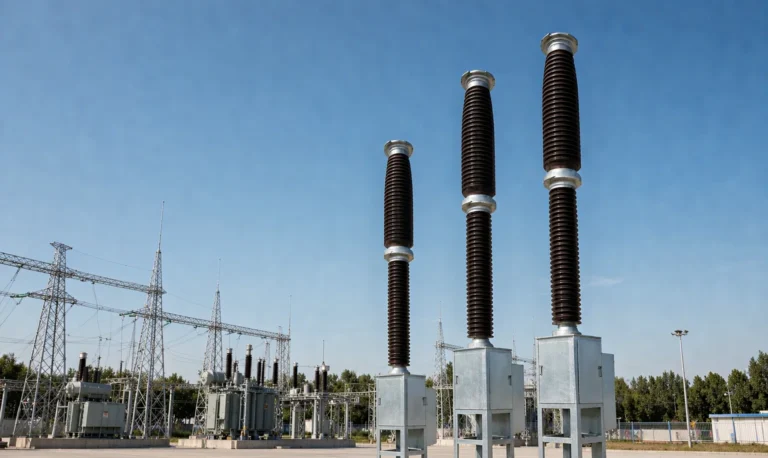
Offshore Wind 66 kV Collection Systems: Breaker Selection for Salt Spray and Vibration
How 66 kV changed the collection system, what C5-M salt spray demands in measurable terms, and why the breaker boundary runs along the shoreline.
Read More
Every hydraulic vs spring operating mechanism comparison written at the tender stage is about speed, energy and price. Almost none of them are about year eleven. Yet year eleven is when the two designs stop looking similar: the spring drive is still quietly charging its spring in fifteen seconds, while the hydraulic drive has begun running its pump four times a day for reasons nobody has written down. Both breakers still pass their timing tests. Only one of them is telling you something.
This article is deliberately not about how either mechanism works — that belongs in our guide to SF6 circuit breaker operating mechanisms. This is about the ten-year ledger: what fails, what does not fail even though everyone suspects it, how to tell a real leak from a temperature effect, and which spare parts you will actually be able to buy when the warranty is a distant memory. If you are specifying new 126 kV or 252 kV breakers, the high-voltage SF6 circuit breaker range is the reference frame for everything below.
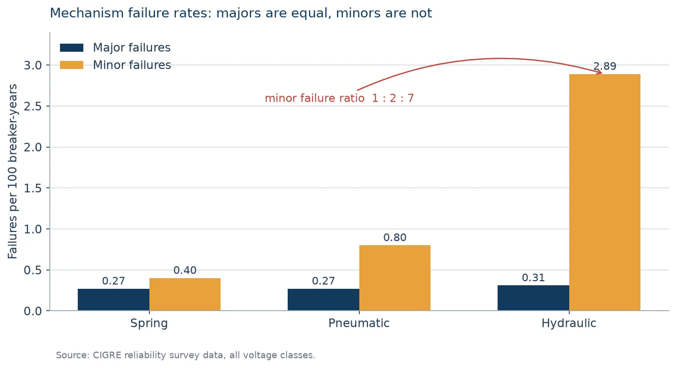
CIGRE’s reliability surveys are the closest thing this industry has to an unbiased service record, and one result from them is routinely misquoted. Across all mechanism types, the major failure rate is essentially identical: roughly 0.27 to 0.31 major failures per 100 breaker-years for spring, pneumatic and hydraulic drives alike. On that metric, nobody wins. Anyone claiming a hydraulic mechanism is intrinsically less reliable than a spring mechanism is reading the wrong column.
The minor failure column is where the designs separate, and the separation is not subtle. The minor failure rate for spring, pneumatic and hydraulic drives runs at roughly 1 : 2 : 7. In the same survey data that works out to about 0.40 minor failures per 100 breaker-years for spring mechanisms against 2.89 for hydraulic ones — a factor of seven, and the survey is explicit about what those minor failures mostly are: hydraulic oil leaks and air leaks. A hydraulic mechanism does not fail more often in the sense that matters to a protection engineer. It needs attention roughly seven times more often, and that attention is a technician with a drip tray and a pressure gauge.
That distinction decides the whole comparison, because minor failures are the ones that generate work orders, oil top-ups, pump replacements and eventually the budget conversation that gets a healthy breaker replaced. The same surveys put mechanical origin in the operating mechanism at about 44 percent of all major failures, with a further 24.5 percent of major failures traced to auxiliary and control circuits — which is why the trip circuit deserves its own supervision, a subject we cover separately under SF6 circuit breaker failure and troubleshooting.
Most English-language comparisons divide the world into spring and hydraulic. That framing misses the design that dominates 252 kV and above in Chinese and much of the Asian market: the hydraulic disc-spring mechanism, where an oil pump compresses a stack of disc springs and the oil circuit does the switching. It is hydraulic in its plumbing and spring in its energy storage, and it behaves like neither parent over ten years. Getting this wrong leads buyers to ask for the wrong spare parts, which is a genuinely expensive mistake.
| Mechanism family | Where the energy lives | What ages first | Typical overhaul horizon |
|---|---|---|---|
| Motor-charged spring | Helical compression spring, held by a latch | Latch surfaces, damper, charging motor brushes | 8–10 years or at the M-class operation count |
| Hydraulic, nitrogen accumulator | Compressed nitrogen behind hydraulic oil | Seals, accumulator bladder or piston, nitrogen precharge | 8–12 years, driven by leak rate not by operations |
| Hydraulic disc-spring | Oil-pressed disc spring stack | Control valve sealing faces, cylinder seals, oil cleanliness | 10–12 years, driven by pump-start trend |
The CIGRE surveys put the average interval between scheduled overhauls at 8.3 years across the fleet, with the observation that it could in many cases be extended. Read that against the table above and the practical implication is clear: the calendar is a poor trigger. What you want is a leading indicator that moves before the calendar does.
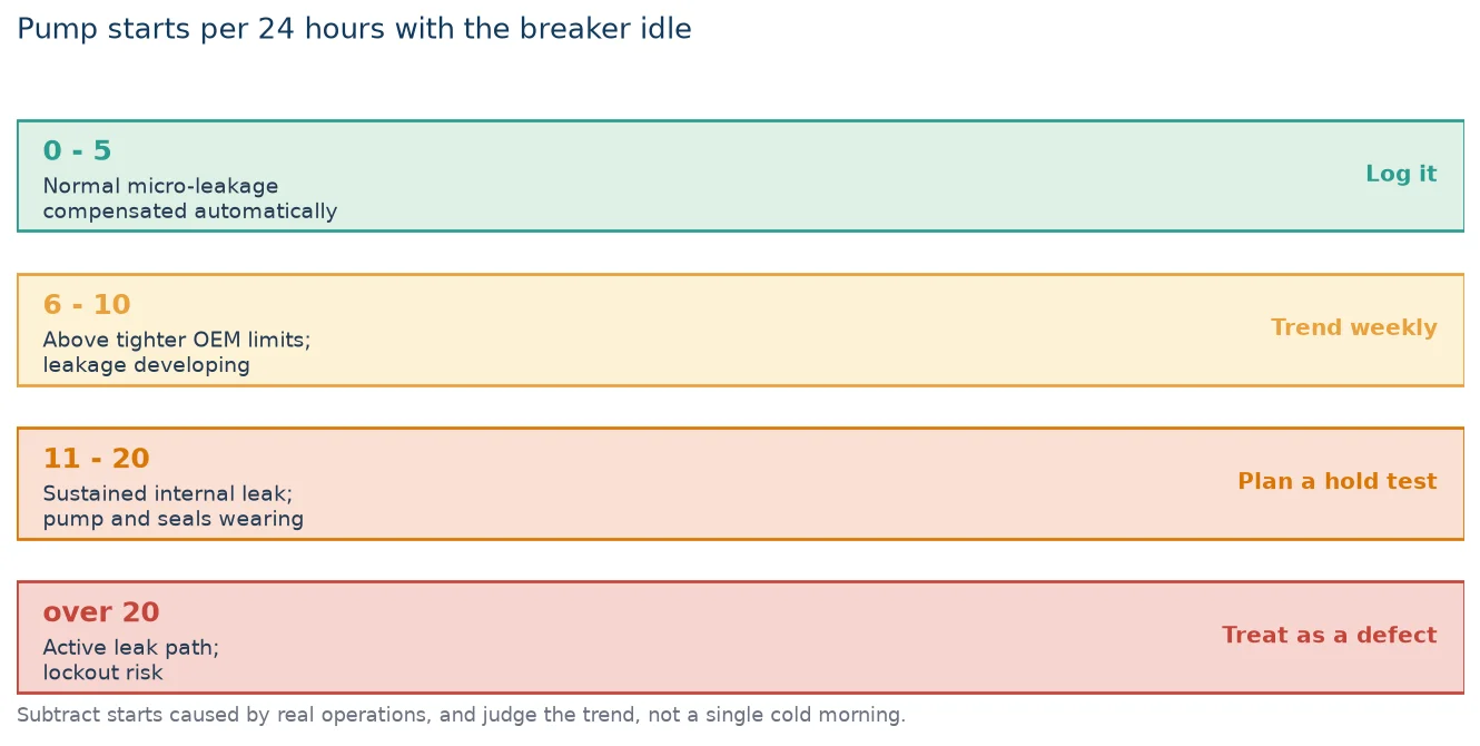
For any hydraulic mechanism, the number of times the pump motor starts in 24 hours with the breaker sitting idle is a direct measurement of internal leakage. Every manufacturer publishes a figure. They differ — one major manufacturer’s manual allows five starts per day, others allow ten — but the escalation logic is consistent across all of them, and it is worth writing on the inside of the mechanism cabinet door.
| Pump starts per 24 h, no operation | What it means | Action |
|---|---|---|
| 0–5 | Normal micro-leakage past metal sealing faces; compensated automatically | Log the number. Nothing else. |
| 6–10 | Above the tighter manufacturer limits; leakage developing | Trend it weekly, inspect joints and oil level, notify the OEM |
| 11–20 | Sustained internal leak; pump and seals wearing faster than design | Schedule a hold test at the next outage; prepare seal kit |
| Over 20, or rising week on week | Active leak path; risk of lockout and slow operation | Treat as a defect. Isolate, locate, repair. |
Two rules make this indicator trustworthy. First, subtract the starts caused by actual breaker operations — a breaker that tripped twice legitimately recharges. Second, never judge a mechanism on one cold morning. Nitrogen precharge and oil viscosity both shift with temperature, so a mechanism that starts twice a day in July and four times a day in January may be perfectly healthy. The signal you are looking for is a trend, not a reading.
This is the most useful diagnostic in the entire hydraulic playbook, and it is almost never written down outside service literature. Note the breaker position when the pump starts, then reason backwards through the oil circuit:
A documented field case makes the point. A 220 kV bus-tie breaker in a 500 kV station was logging 19 pump starts in 24 hours, with no visible external oil. Because the starts happened in the closed position, the technicians went straight to the closing first-stage valve, applied a slight positive pressure with the low-pressure tank removed, and watched oil weep from that valve’s drain port. The cause was metal debris from manufacturing lodging on the ball valve seat at the moment of closure. No amount of seal replacement would have fixed it. Position-first diagnosis turned a mechanism teardown into a valve cleaning.
Ask a maintenance team what worries them about a disc-spring mechanism and the answer is usually the springs. The data does not support that worry, and the reason is instructive.
Disc springs lose force in two distinct ways. Relaxation is progressive loss of force under sustained load at temperature — and per DIN 2093 / EN 16983 it is essentially a settling phenomenon: a stabilised stack loses on the order of five percent of its force in the first couple of weeks of service and then plateaus, with subsequent loss becoming negligible. That is why the standard requires presetting, and why a mechanism that has held its pressure for nine years is not about to lose it to relaxation in year ten.
Fatigue is a different mechanism, and it is governed by the stress range, not the stress level. Disc spring fatigue life is estimated from the stress differential at points II and III between the preloaded and the fully deflected position; the standard’s fatigue diagrams assume a ninety-nine percent survival rate. Two rules of thumb carry most of the engineering: preload should be at least fifteen percent of available deflection, and maximum deflection should not exceed seventy-five percent. Run a spring from fifteen to seventy-five percent deflection and the estimated life sits around a hundred thousand cycles. Run the same spring from twenty-five to fifty percent and the estimate climbs past two million cycles. Halving the working stroke multiplies the life by a factor of twenty.
A breaker operating mechanism does not cycle anything like a hundred thousand times in ten years — IEC 62271-100’s M2 class asks for 10,000 operations, and M1 for 2,000. Unless the mechanism is on a duty that hammers it — capacitor bank switching, arc furnace duty, back-to-back switching — the disc spring stack is not the component that ends the mechanism’s life. The seals and the valve faces are.
On a ten-year-old hydraulic mechanism, the spring has settled and stabilised. The oil circuit has not. Budget for seals and valves, not for springs.
The spring drive’s ten-year failures are less frequent but more varied, because it has more moving parts in the energy path. The closing spring is charged by a motor through a reduction gear and held by a latch; on closing, part of the spring energy closes the breaker and the rest charges the opening spring, which is then held by a second latch. Four things carry the wear.
| Component | Ten-year failure signature | How you catch it early |
|---|---|---|
| Closing and opening latches | Wear and indentation on the latch face; occasional refusal to latch or to release | Coil current signature, trip time scatter beyond a few milliseconds, visual inspection at each service |
| Charging motor and gear train | Brush wear, rising charging time, current draw climbing well above the healthy band | Time the charge from a discharged spring every service; record the value |
| Damper / dashpot | Contact bounce and overtravel growing; noise at end of travel | Travel curve comparison against the commissioning trace — see our guide to reading a breaker travel curve |
| Closing spring | Loss of free length, force retention drifting, corrosion pitting acting as a stress riser | Measure free length and compare with nameplate; inspect coil ends where stress concentrates |
The travel curve deserves particular emphasis because it is the one test that catches almost all of the above without opening anything. A mechanism whose closing time has drifted fifteen percent from its commissioning value, or whose bounce pattern has changed shape, is telling you which of the four rows above to look at. Recording the commissioning trace and keeping it is worth more than any single spare part.
For a concrete baseline on what these mechanisms look like when specified for long mechanical life, our LW36-126 model explainer covers the 3150 A, 40 kA configuration and the mechanical endurance class it is built to.
When the pump-start count is ambiguous, or when a mechanism has just been repaired and someone wants to sign it off, the definitive test is a pressure hold with the motor disconnected. The procedure is identical across manufacturers; only the acceptance number moves.
Do it in both positions if the mechanism leaks position-dependently, and allow at least eight hours per test so that a slow leak has time to express itself. After a repair, the acceptance criteria are usually stricter: no external weeping at zero gauge over 24 hours, then 12 hours at rated pressure in the open position and 12 hours in the closed position, with total pressure drop within the manufacturer’s allowance — commonly 1.0 MPa. Cleaning fluid matters too: components are typically washed in clean No. 10 aviation hydraulic oil, not solvent, and O-rings are fitted with a light silicone grease film so they seat without twisting.
This is the part of the comparison that procurement teams remember, because it is the part that shows up as an unbudgeted line item. The question is not which mechanism has cheaper parts. It is which parts you can still obtain, in what quantity, and how fast.
| Spare | Spring mechanism | Hydraulic mechanism |
|---|---|---|
| Seals and gaskets | Minimal — no pressurised oil circuit | Full O-ring and seal kit is the single most-used item; buy two kits at commissioning |
| Coils (trip / close) | Standard, interchangeable, widely stocked | Same, but valve solenoids add a second family of part numbers |
| Energy storage element | Closing spring — heavy, model-specific, long lead time | Disc spring stack or accumulator bladder; stack rarely replaced, bladder and precharge serviceable |
| Pump / motor | Charging motor with brushes and gear train | Piston pump plus motor; pump is a wear item on a leaking mechanism |
| Valves | None | First-stage valves, changeover valve, safety valve, check valve — the parts that actually fail |
| Oil and consumables | Grease and damper fluid | Hydraulic oil, filters, cleanliness control — an ongoing consumable budget |
The asymmetry is not about cost per part. It is about the number of distinct part numbers that can strand a breaker. A spring mechanism has a short spare list; a hydraulic mechanism has a long one, and the long tail is exactly where obsolete part numbers live. If you are buying 252 kV equipment for a twenty-five year horizon, ask for the mechanism spare parts list as a contract annex, with a written availability commitment. Our customized LW-252 configuration is the platform where that conversation usually happens, because at that voltage the mechanism is a larger share of the total risk.
Almost every ten-year problem is cheaper to prevent in the specification than to solve in the field. Five clauses carry most of the value:
For the routine side of this — intervals, checklists and what belongs in an annual service — the SF6 circuit breaker maintenance guide covers the schedule that these leading indicators feed into.
Not in major failure terms. CIGRE survey data puts major failure rates for spring, pneumatic and hydraulic mechanisms within a few hundredths of a percent of each other per 100 breaker-years. The real difference is in minor failures, where hydraulic mechanisms run roughly seven times higher, driven almost entirely by oil leakage. If your definition of reliability includes maintenance workload, the spring mechanism wins. If it only counts failures to operate, they are close to equal.
There is no universal calendar interval, and any supplier quoting one without reference to oil analysis is guessing. The defensible approach is condition-based: sample annually for cleanliness, water content and colour, and replace when the sample degrades rather than when a date arrives. Oil that has gone dark, cloudy or emulsified, or that carries metal particles, indicates a mechanical problem that an oil change alone will not solve.
It loses a small amount early and then stabilises. Per DIN 2093 / EN 16983, a preset stack typically sheds around five percent of its force in the first weeks of service and then plateaus, with further loss negligible. Fatigue is a separate mechanism governed by stress range, and at the operation counts a typical transmission breaker accumulates — M2 class is 10,000 operations — it is rarely the limiting factor. On a ten-year-old mechanism, pressure loss is far more likely to be a seal than a spring.
Manufacturers publish limits between five and ten starts per 24 hours with no breaker operation, so use your own manual’s figure as the first threshold. Above ten, trend it weekly and inform the OEM. Above twenty, or any count that is climbing week on week, treat it as a defect and locate the leak. Always subtract starts caused by real operations and discount short-term temperature effects before drawing conclusions.
Indirectly, yes. A sustained leak causes the pump and seals to wear faster, and as pressure margin erodes the breaker’s opening and closing speeds fall. Mechanisms also carry a low-pressure lockout that blocks operation below a set threshold. The failure mode is therefore not usually a sudden refusal but a slow degradation of speed followed by a lockout — which is exactly why the pump-start count is worth monitoring rather than reacting to.
Both need attention, for different reasons. Hydraulic mechanisms depend on oil viscosity, which rises steeply as temperature falls, and on accumulator precharge behaving predictably across the range; heater circuits and correct oil grade are essential. Spring mechanisms have no fluid to thicken but do have grease that stiffens and damper fluid that changes behaviour. Our article on cold climate and high altitude operation covers the temperature-dependent design choices in more detail.
Treat the hydraulic vs spring operating mechanism decision as a twenty-five year maintenance commitment rather than a first-cost comparison, and the choice usually makes itself. Choose a spring mechanism when the duty is moderate, the maintenance team is small, and you want the shortest possible spare parts list. Choose a hydraulic mechanism when you need high energy in a small volume, when the breaker is large, or when the required operating speed and consistency cannot be met by a spring drive. Neither choice is wrong. What is wrong is buying a hydraulic mechanism without a leak-monitoring habit and a seal kit on the shelf, or buying a spring mechanism and never recording a travel curve.
Ten years is long enough for a mechanism to reveal its character and short enough that the wrong choice is still expensive to unwind. If you are specifying 126 kV or 252 kV breakers and want the mechanism, the spare parts list and the maintenance intervals settled in one document, the SF6 circuit breaker technical library is the place to start, and our engineers will work through your duty cycle rather than a catalogue.