Bushing Current Transformers in Dead-Tank Breakers: Ratios, Classes and Space Savings
Published: Author: Lisa
A dead tank breaker can carry four or five current transformer cores on each bushing because the tank is earthed and the bushing is the only place where primary current crosses the ground boundary. That single geometric fact is why a dead tank breaker current transformer costs less, occupies less yard and is tested more consistently than a set of free-standing CTs, and it is also why the ratio you pick at order time is the ratio you live with.
Most specifications handle the CTs in one line: “bushing CTs as per protection philosophy”. That line hides the decisions that cause commissioning problems two years later, when a metering core reads badly at light load, a protection core saturates during a through-fault, or a ratio change turns into a bushing replacement. This guide works through the core allocation, the ratio arithmetic, the accuracy classes, the burden calculation that decides whether your 5P20 behaves like a 5P20, and the space and cost case for integration.
Why the CT sits on the bushing
In a dead tank breaker the interrupter is inside a metal enclosure at earth potential, and the conductor reaches the line through bushings on the tank top or side. The bushing’s centre conductor is therefore a straight run of primary conductor surrounded by insulation and then by earth. A toroidal core slid over that conductor, with a secondary winding on it, is a current transformer. Nothing else is required: no separate primary conductor, no separate insulation column, no separate foundation. The dead tank breaker current transformer shares the bushing’s insulation rather than owning a set of its own.
In a live tank breaker the interrupter sits at line potential on top of a support column, so any CT has to sit at line potential too, and the secondary signal has to come down to earth through a fibre optic link or a CT cable running inside the column. It works, but it is a different engineering problem with a different failure mode.
This is the practical reason dead tank construction dominates where CT density is high: North American transmission practice, and every gas-insulated substation. The construction trade-offs beyond the CTs are covered in the comparison of live tank and dead tank SF6 circuit breakers.
How many cores, and what goes on each
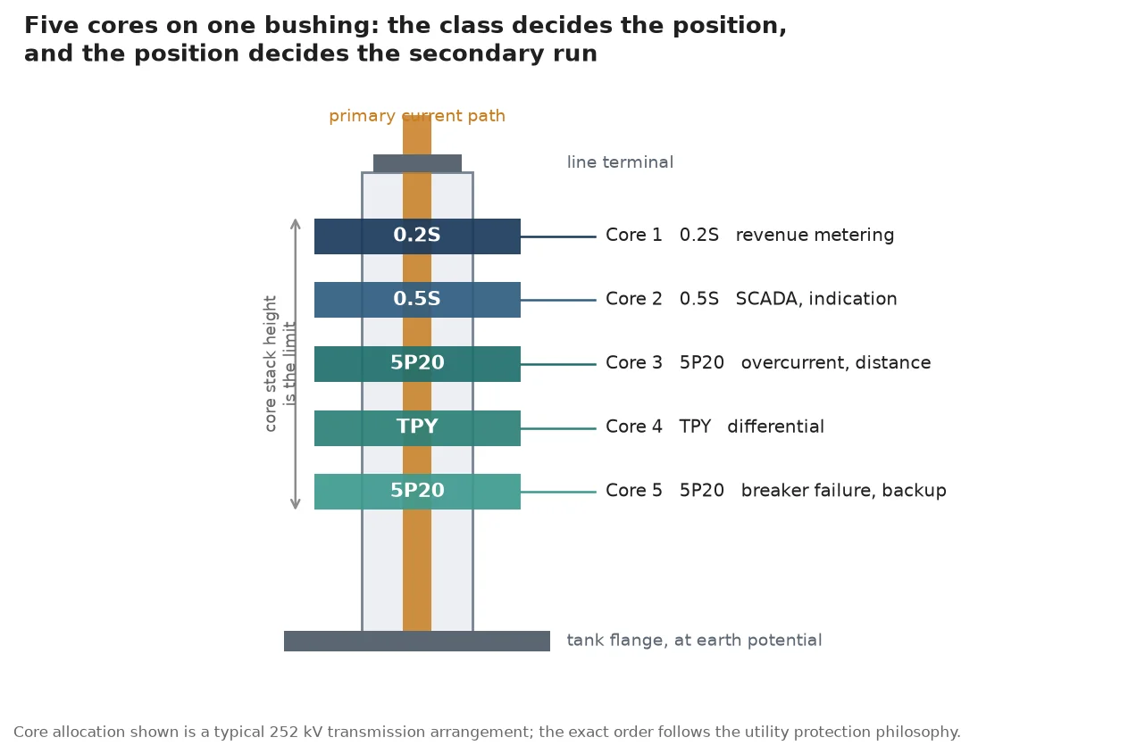
A transmission bay does not need one CT; it needs several independent measurements of the same current, for different consumers, with different accuracy requirements and different failure consequences. On a 252 kV dead tank breaker, four to five cores per bushing is normal.
Core
Typical class
Consumer
Position on the bushing
What it must survive
1
0.2S
Revenue metering
Top, nearest the line terminal
Accuracy down to 1 percent of rated current; must not saturate at maximum load
2
0.5 or 0.5S
SCADA, indication, power quality
Upper middle
Moderate accuracy, wide current range
3
5P20 or 5P30
Overcurrent and distance protection
Middle
Composite error within 5 percent up to the accuracy limit factor
4
TPY, PX or 5P30
Differential protection
Lower middle
Defined knee point voltage and low remanence, matched across the zone
5
5P20
Breaker failure, backup
Bottom, nearest earth
Survives the highest through-fault without saturation
The ordering is not arbitrary. Placing the metering core nearest the line terminal puts it as far as possible from the tank’s stray flux, and putting the backup core nearest earth shortens the secondary run.
Metering nearest the line terminal, backup nearest earth; the stack height between them is the real constraint.
On a three-phase unit the cores must also be matched: differential protection compares currents from two or more sets of cores, and a TPY core with different remanence behaviour on one side will produce a spurious operate signal during a through-fault even when nothing is wrong.
Ratio selection, and the trap of the oversized CT
The instinct when specifying a ratio is to leave headroom for future load. The instinct is wrong more often than it is right, and the arithmetic shows why.
Take a 600/5 A core, ratio 120:1. Under a normal load of 40 A, the secondary current is 0.33 A. A class 0.5 core without the “S” suffix is only guaranteed from 5 percent of rated primary current upward, which on this core is 30 A. So the core is technically in range, but only just, and it has no margin below. If the load falls to 20 A at night, the reading is outside the guaranteed band, and a revenue meter built on it will drift in exactly the direction that costs money.
The rule that avoids this: choose the ratio so that normal load sits between 40 and 60 percent of rated primary current, and check the low end against the class you actually bought. A 0.2S or 0.5S core is guaranteed from 1 percent of rated, which gives a far wider useful band, and that is why the “S” classes exist on metering cores in lightly loaded networks.
Multi-ratio cores buy back some flexibility. A core wound with series-parallel sections can be connected as, for example, 1200/600 A or 2000/1000/500 A, with the taps brought out to the terminal box. This is a real advantage at specification time, but note the constraint: the taps must be selected with the primary isolated, and changing a tap on a live bay is not an option. Multi-ratio also means more terminals in a small box, which is a wiring-error opportunity.
Accuracy classes: what the letters actually buy
The IEC 61869-2 class system looks opaque and is not. Two numbers and a letter cover almost everything.
Accurate measurement where load is steady and high
0.5
Metering
0.5 percent
5 percent of rated current
Panel indication, SCADA
5P20
Protection
5 percent composite error up to 20 times rated
Rated current
Overcurrent, distance, backup
5P30
Protection
5 percent up to 30 times rated
Rated current
High fault level, close-in faults
10P20
Protection
10 percent up to 20 times rated
Rated current
Applications tolerant of coarser measurement
PX, TPY, TPZ
Protection, special
Defined by knee point voltage and winding resistance
Specified
Differential and unit protection where remanence matters
The critical point is that a protection class is meaningless without its accuracy limit factor and its rated burden. “5P20” says the composite error stays within 5 percent up to 20 times rated current, but only at the rated burden. Halve the burden and you get more headroom; double it and the core saturates well before 20 times, and the relay sees a distorted, under-represented fault current exactly when it needs the truth.
The second critical point is that composite error is not the same as ratio error. Composite error includes the phase displacement and the harmonic content of the magnetising current, which is why a core can pass a ratio test on the bench and still misbehave in service.
Burden: the arithmetic people skip
Burden is everything on the secondary side: the relay input, the meter, the terminal blocks, the test links and, usually the largest term, the secondary cable. A 30 VA core rating sounds generous until you price the cable.
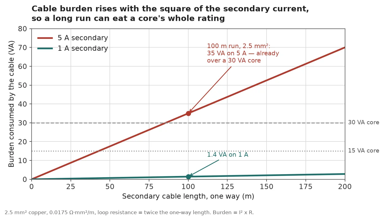
Consider a 100 m run from the breaker terminal box to the control building, using 2.5 mm² copper. The loop resistance is twice the run length, at roughly 0.007 Ω per metre for that cross-section, so about 1.4 Ω. On a 5 A secondary, the cable alone draws 5² × 1.4, or 35 VA. That is more than a typical 30 VA core rating, before the relay is connected.
Change the secondary to 1 A and the same cable draws 1² × 1.4, or 1.4 VA. Twenty-five times less, for the same wire. This is the whole argument for 1 A secondaries on long runs, and it is why high-voltage installations with a control building 150 m away routinely specify 1 A while compact distribution bays stay on 5 A.
A hundred metres of 2.5 square millimetre cable consumes 35 VA at 5 A and 1.4 VA at 1 A; the core rating does not move.
The calculation to run at specification time is short: sum the relay and meter burden in VA, add the cable term as current squared times loop resistance, and compare the total against the rated burden of the core. If the total exceeds the rating, either the class is not what you think it is, or you need a larger core, a shorter run, or a 1 A secondary.
Two further burden effects are worth remembering. First, a modern numerical relay typically draws under 0.5 VA per current input, against several VA for an electromechanical one, so a refurbishment that swaps relays can free up a large part of the budget. Second, the DC component in an offset fault current saturates a core faster than the symmetrical current would, particularly near generators and large transformers with a high X/R ratio, so a core that just passes the burden arithmetic on symmetrical current can still saturate on the first cycle of a real fault.
Space and cost: what integration is actually worth
Free-standing CTs are not just an extra item on the bill of materials. Each one needs a primary connection to the breaker, a support structure, a foundation, an earth connection, a secondary cable route and its own space in the yard with the clearances that go with it. Integrating the cores into the bushings removes all of it.
Item
Bushing CTs in a dead tank breaker
Free-standing CTs
Yard space
None beyond the breaker
One structure per phase per set, with clearances
Primary connections
None, the bushing conductor is the primary
Two extra conductor joints per CT
Foundations and steel
None
Per structure
Secondary route
Short, inside the breaker to the terminal box
Longer, with more terminations
Factory testing
Ratio, polarity and excitation tested with the breaker
Tested separately, then re-verified at commissioning
Ratio flexibility after order
Fixed or tapped at the terminal box
Replaceable as a separate unit
Failure consequence
May require bushing work
Replace the CT
The published cost evidence is stronger than the usual “it saves space” claim. Transpower, the New Zealand transmission operator, documented a bus security project where dead tank disconnecting circuit breakers with integral current transformers replaced the conventional arrangement of separate breaker, CTs and disconnectors. The integrated units fitted inside the existing yard at the required safety and maintenance clearances; the conventional arrangement would have required extending the yard and relocating several 110 kV bays. The avoided cost was estimated at NZ$0.8 million to NZ$1.4 million, plus a further NZ$0.4 million in reduced disconnector maintenance over the asset life.
That is a transmission-operator scale number, and it will not map onto a single industrial bay. What maps is the structure of the argument: the saving is not in the CT price, it is in the yard, the foundations, the primary joints and the second outage that never happens.
What integration costs you
The trade is real and worth stating plainly, because a specification that ignores it produces a project that cannot adapt.
The ratio is fixed at order. A multi-ratio core buys some flexibility, but the number of cores, their classes and their order along the bushing are frozen. A protection philosophy change five years later may not fit.
A failed core is a bushing problem. Replacing a core inside a dead tank means opening the tank and disturbing the bushing, which is a different job from swapping a free-standing CT on a Saturday.
Testing access is worse. Primary injection into a bushing CT means working at the bushing, and secondary work happens in the breaker terminal box rather than at a convenient ground-level CT.
Spares strategy changes. You either hold a spare core set, which is unusual, or accept the lead time. Free-standing CTs are easier to source from stock.
None of these outweigh the space and cost case for most transmission and industrial projects. They do argue for getting the specification right the first time, which is the next section.
Specifying the CTs in the technical protocol
Nine items, in the order that causes trouble if they are missing.
Core count, class and order along the bushing, per phase. State which core is nearest the line terminal.
Ratio with all taps, and the connection for each tap, with a drawing of the terminal arrangement.
Rated burden in VA for each core, and the burden at which the class is guaranteed.
Accuracy limit factor for every protection core, and the knee point voltage for any PX or TPY core.
Secondary current, 1 A or 5 A, per core, not per breaker. Mixed secondaries on one bushing are possible and should be stated.
Short-time thermal current and duration, typically quoted as a multiple of rated primary current for 3 s, plus the dynamic rating as a multiple of the thermal value.
Insulation level of the secondary circuit, and the partial discharge limit of the assembly at rated voltage.
Test report to IEC 61869-2: turns ratio within a tight tolerance of nameplate, polarity, insulation withstand, excitation curve for protection cores, composite error, partial discharge.
Interface drawing covering the bushing diameter, the core stack height, the terminal box position and the cable entry direction.
Never open a CT secondary while primary current flows. An open secondary on a loaded core develops a high voltage across the open terminals, damages the insulation and is a live-part hazard. Test links and shorting blocks belong in the design, not in the procedure.
Verify polarity before the bay is energised. A reversed core produces a differential protection that operates on load and restrains on faults, which is the worst possible failure mode because it looks like a settings problem. Battery and voltmeter, or a secondary injection set, before commissioning.
Measure the actual burden, not the drawing burden. Cable routes change on site. A burden measurement taken at the terminal box with the real wiring in place catches the case where the installed cable is longer or thinner than the design.
For routine maintenance, the practical cycle is insulation resistance every few years, ratio and excitation at longer intervals or after a fault, and partial discharge testing where the history justifies it. The CT itself has no moving parts; almost every failure traces back to moisture ingress, a loose termination, or a burden that was never checked.
Putting the decision together
For a transmission or large industrial bay, the integrated arrangement is the default because the space, foundation and primary-joint savings are large and measurable, and because factory testing of the complete assembly removes a whole class of commissioning errors. The engineering effort belongs in the specification: the core allocation, the ratio against real load, the burden arithmetic and the class of each core.
For a project where the protection philosophy is likely to change, or where CT replacement without touching the breaker is a hard requirement, free-standing CTs remain the more adaptable choice, at the cost of yard space and connections.
How many CT cores can a dead tank breaker bushing carry?
Four to five is typical on a 252 kV transmission bay, and six is possible on larger bushings. The limit is the stack height available on the bushing and the size of the terminal box, not the electrical principle. Each additional core adds height, weight and secondary wiring, so the count is a protection philosophy decision rather than a manufacturing limit.
Can I change the CT ratio after the breaker is delivered?
Only within the taps that were built in. A multi-ratio core can be reconnected between its taps with the primary isolated, but the turns ratio itself is fixed by the winding. A genuine ratio change means new cores, which on a dead tank breaker means bushing work. This is the strongest argument for getting the ratio right at the specification stage.
What is the difference between 0.2 and 0.2S?
The “S” extends the guaranteed accuracy range down to 1 percent of rated current instead of 5 percent. On a lightly loaded line, or one with a large day-night swing, that is the difference between a meter that is accurate across the whole cycle and one that is only accurate at peak. Revenue metering on transmission interconnections is normally specified as 0.2S for this reason.
Why does my 5P20 core saturate during a fault?
Almost always because the connected burden exceeds the rated burden, or because the DC offset in the fault current saturates the core on the first cycle. Composite error is guaranteed at the rated burden and on symmetrical current. Check the measured burden first, then the X/R ratio of the source, then whether the accuracy limit factor was specified against the actual maximum through-fault current.
Should I specify 1 A or 5 A secondaries?
1 A where the secondary run is long, because the cable burden falls with the square of the current and a 1 A secondary consumes twenty-five times less VA on the same wire. 5 A where runs are short and the existing relay fleet, test equipment and practice are built around 5 A. Mixing the two on one site adds a class of wiring error for no benefit.
Are bushing CTs less accurate than free-standing CTs?
Not inherently. The core, winding and insulation are the same technology; the difference is that a bushing CT shares the bushing’s insulation and has less room for a large core. Where the accuracy requirement is extreme, a free-standing CT with a bigger core and more secondary turns is easier to provide. For the classes used in normal transmission protection and metering, integrated cores meet the same IEC 61869-2 limits.
The relative leak rate formula, a mass-balance worked example, the pressure-trend cross-check, what 0.5% vs 1% costs in CO2e and the fields an audit-ready annual report needs.
UHF, acoustic and IEC 60270 partial discharge detection for GIS compared: sensitivity and calibration limits, sensor placement, PD pattern signatures and how to scope online monitoring.
The seven landmarks of a healthy trip coil waveform, the three fault signatures that separate low voltage from mechanical binding, and how to record a baseline worth comparing years later.