Offshore Wind 66 kV Collection Systems: Breaker Selection for Salt Spray and Vibration
How 66 kV changed the collection system, what C5-M salt spray demands in measurable terms, and why the breaker boundary runs along the shoreline.
Read More
A dead trip coil is the cheapest failure in the substation and the most expensive one to discover. The coil itself costs less than a decent torque wrench. The feeder it fails to clear costs whatever a fault burns through before the backup protection at the next station up the line decides to act — assuming it can see the fault at all through the impedance of a transformer and a line.
What makes this failure class so dangerous is that it is invisible. Nothing trips, nothing alarms, no lamp goes out. The breaker sits closed with a trip circuit that looks exactly like a working one, right up to the moment a protection relay closes its trip contact and nothing happens. Trip circuit supervision exists to close that gap: a continuous, low-current check of the entire trip path that raises an alarm when continuity or control voltage is lost. This article covers the three wiring schemes in real use, the current arithmetic that makes them safe, the delay settings that stop them crying wolf, and how to commission one so that it actually proves what it claims.
It is a companion to our broader piece on SF6 circuit breaker failure and troubleshooting, which covers the diagnosis sequence when a breaker misbehaves. Supervision is the other half of that story: catching the defect while the breaker is still healthy. Everything below applies to the breakers in our high-voltage SF6 circuit breaker range, and to any other make whose mechanism box you can open.
A trip circuit is a series path with more single points of failure than most people assume. Between the DC positive bus and the trip coil sit protection relay contacts, test links, fuses or MCBs, terminal blocks, interposing relays and the breaker’s own 52a auxiliary contact. Each of them can open. Each of them can also develop a high-resistance joint that passes enough current for a multimeter to look reassuring while failing to pass enough to move a plunger.
| Failure point | What happens | Does supervision see it? |
|---|---|---|
| Open trip coil winding | No electromagnetic force; breaker never unlatches | Yes, in both breaker positions |
| Broken or disconnected wire | Path open at a terminal or in a multicore | Yes, if the break is inside the supervised segment |
| Blown fuse or tripped MCB in the trip supply | Whole circuit dead | Only if the supervision alarm is fed from a different supply |
| Lost DC control supply | Nothing in the circuit can operate | Only with an independent, monitored alarm supply |
| 52a auxiliary contact failure | Coil cannot be energised from the protection relay | Yes — and this is the case that single-position schemes miss |
| Corroded or loose terminal with high resistance | Passes milliamps, fails to pass amps | Partially — this is the classic blind spot |
| Seized trip coil plunger | Coil energises, latch never releases | No. Only coil current signature analysis catches this |
That last row matters. Supervision proves electrical continuity, not mechanical release. A coil whose plunger is gummed up will pass every supervision check forever and still fail to trip. This is precisely why coil current signature analysis — watching the shape of the current trace as the plunger moves and generates back-EMF — is a separate diagnostic rather than a substitute. Our guide to reading a breaker travel curve covers the mechanical side of the same question.
The trick that makes continuous supervision work is that the trip coil has two different healthy states, and the breaker’s auxiliary switch can select between them. The 52a contact is normally open and closes when the breaker closes; the 52b contact is normally closed and opens when the breaker closes. International practice, as reflected in IEC 62271-1 and the switchgear conventions that follow it, puts a normally open 52a contact in series with the trip coil and returns the coil to the DC negative bus. That arrangement does two jobs: it interrupts coil current as soon as the breaker opens, and it prevents a latched trip contact from cooking the coil.
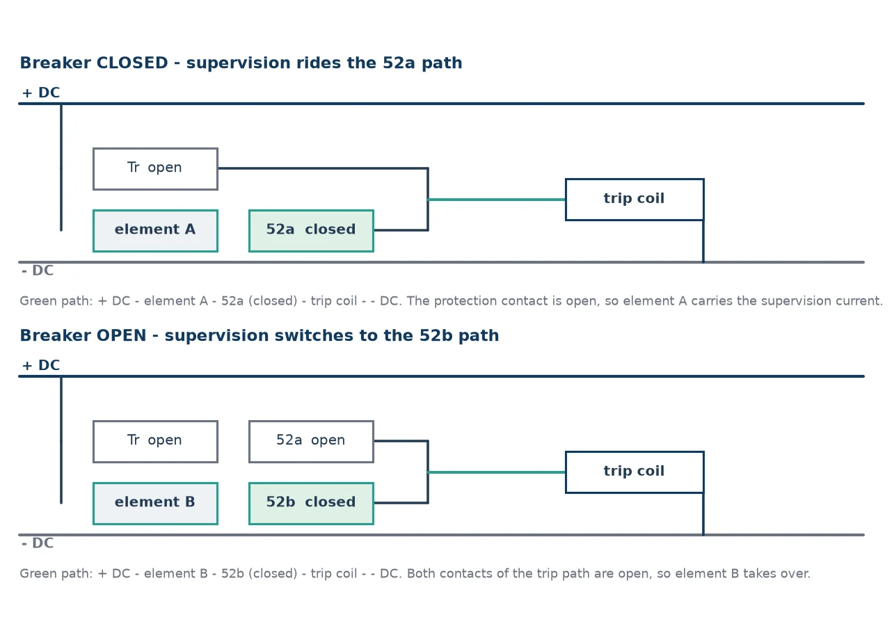
Because 52a is closed when the breaker is closed and 52b is closed when it is open, a supervision element placed across the trip contact can find a path through the trip coil in either stable position — provided it uses the right auxiliary contact for each state. That is the whole architecture. Everything else is detail about how much current to inject and how long to wait before believing a bad reading.
| Scheme | Coverage | Strength | Weakness |
|---|---|---|---|
| Single element, post-close only (52a path) | Trip path while the breaker is closed | Simple, cheap, adequate for many distribution applications | Blind while the breaker is open; misses a coil that fails between operations |
| Two element, pre- and post-close (52a plus 52b) | Trip path in both stable positions | Continuous coverage; catches an open coil before the next close | Needs careful timing so the transition does not alarm |
| Relay-integrated supervision with independent alarm supply | Both positions plus loss of trip supply | Reports the failure of the very supply it depends on | Requires a second, monitored DC source and correct logic configuration |
The middle scheme is the practical default for transmission and for any breaker whose failure to trip would be consequential. The pre-close path uses 52b in parallel with the 52a path so that supervision current can flow through the trip coil while the breaker sits open. In the classic electromechanical implementation, relay A is energised through the healthy closed-breaker path and its normally open contact keeps alarm relay C picked up, holding C’s normally closed alarm contact open. When the breaker opens, relay B takes over through the 52b path and keeps C energised the same way. Lose either path and C drops out, closing the alarm contact.
There is one configuration where a well-designed supervision scheme reports healthy while the trip path is dead, and it catches people out. If the protection trip contact is latched — for example the output of a lockout relay that stays closed until manually reset — then a closed trip contact can short out one supervision element and mask a break in the path it was supposed to watch. The supervision circuit keeps reading continuity through the latched contact while the actual trip path is open. The fix is to supervise the path that the latched contact does not bypass, which is why the 52b branch exists and why its alarm must not be defeated by a contact that stays closed for minutes after a trip.
Supervision works by injecting a small current through the trip coil at all times. Two constraints define the window: the current must be large enough for the supervision element to detect reliably, and small enough that it can never operate the trip coil. The classic electromechanical trip supervision relay uses something on the order of three milliamps; modern relay inputs are in the same region. Against a trip coil that draws an amp or two when energised, that is a margin of several hundred to one.
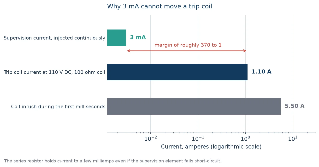
The element that makes this safe in a fault is the series resistor. Without it, a supervision lamp or relay input that fails short-circuit would connect the control supply directly across the trip coil and trip the breaker — the supervision system causing the very event it was installed to prevent. Sizing it is straightforward arithmetic. Pick the target supervision current, subtract the resistance of the trip coil and the supervision element, and size the resistor for continuous dissipation.
| Parameter | 110 V DC control | 220 V DC control |
|---|---|---|
| Target supervision current | 3 mA | 3 mA |
| Total loop resistance required | ≈ 36.7 kΩ | ≈ 73.3 kΩ |
| Less trip coil (100 Ω) and element (5 kΩ) | ≈ 31.6 kΩ | ≈ 68.3 kΩ |
| Resistor dissipation at 3 mA | ≈ 0.28 W | ≈ 0.61 W |
| Recommended resistor rating | 1 W minimum | 2 W minimum |
| Current if the supervision element fails short | ≈ 3.5 mA | ≈ 3.2 mA |
The last row is the one that proves the design. Even with the supervision element shorted out, the resistor limits fault current to a few milliamps — roughly three orders of magnitude below the trip coil’s operating current. If a proposed scheme cannot demonstrate that number, it is not a supervision scheme, it is a nuisance trip waiting for a component failure.
Two practical notes. The resistor must be rated for continuous dissipation, not for the supervision current alone — a quarter-watt part running at 0.28 W will cook itself and eventually fail open, which looks exactly like a genuine trip circuit fault. And the resistor must be mounted where its heat has somewhere to go, not bundled against control wiring insulation.
Every time the breaker operates, the supervision current path is interrupted for the duration of the operation. The 52a and 52b contacts pass through a transient state where neither is properly closed; the trip contact is closed while the breaker is still moving. A supervision scheme without a delay would alarm on every single trip. The delay must therefore exceed the breaker’s operating time plus the auxiliary contact transition, with margin.
Published settings cluster in the 400 to 550 millisecond range, with some relays using a two-stage arrangement — a shorter pickup with a longer confirm, such as 150 ms followed by 400 ms. The design rule is simple: the delay must be longer than the slowest legitimate interruption of the supervision path and shorter than the time in which a real defect could cause harm. For a breaker with a 40 to 60 millisecond opening time and an auxiliary switch that over-travels for perhaps another 20 milliseconds, 400 milliseconds is generous margin with no meaningful loss of protection.
Where people get this wrong is in the interaction with reclosing. During an auto-reclose cycle the breaker is open, then closed, then possibly open again within a few hundred milliseconds. If the alarm delay is set close to the dead time, a legitimate reclose sequence will produce spurious alarms that train the operators to ignore the signal. Check the delay against the actual reclose dead time on your system, not against a default. Our article on auto-reclosing and combined reclosing covers the timing that this interacts with.
| Symptom | Likely cause | What to check |
|---|---|---|
| Alarm on every operation, clears itself | Delay shorter than operating time plus auxiliary transition | Measure actual 52a/52b transition time, extend the delay |
| Alarm on every reclose | Delay shorter than the reclose dead time | Compare the setting against the protection scheme’s dead time |
| No alarm with a genuinely open trip coil | Supervision path paralleled by a latched trip contact or a wiring error | Trace which element is bypassed in the open position |
| Alarm does not appear when trip DC is lost | Alarm circuit fed from the same failed supply | Confirm the alarm has an independent, monitored source |
| Intermittent alarm in humid weather | Moisture in terminal blocks or a marginal resistor | Insulation resistance on the supervised segment, thermography on the resistor |
| Alarm clears when the panel door is moved | Mechanical strain on a terminal or a cracked wire | Wiggle test at terminals with the circuit isolated from tripping |
The fourth row is the most important one and the easiest to get wrong. If the alarm indication is powered from the trip supply, then the loss of that supply disables both the trip function and the alarm that was supposed to report it. The alarm must come from a separate, monitored source — a different battery, a different DC bus, or at minimum a supply whose own health is separately supervised. Anything else is a scheme that reports good news right up until the moment it cannot.
A supervision scheme that has never been tested is a green lamp with a wiring diagram attached. The commissioning test is short and it should be treated as mandatory rather than optional, because the failure modes above are all invisible in normal service.
Step five is where most schemes fail first commissioning, and it is almost always the delay. Step three is where schemes that were wired to supervise only the coil get found out. Neither test takes more than a few minutes and both are far cheaper than the alternative.
Trip circuit supervision is panel-side engineering, but what it protects lives on the breaker. The trip coil, its plunger and the latch it releases are inside the mechanism, and the auxiliary switch that makes the whole scheme possible is bolted to the same shaft that drives the main contacts. On our 40.5 kV medium-mounted outdoor SF6 breaker the trip coil and auxiliary switch are accessible from the mechanism box with the breaker earthed, which is what makes step two of the commissioning list practical in the field rather than a workshop job.
For 126 kV applications the same considerations scale up, with the addition that two independent trip coils become the norm rather than an option — each supervised separately, each capable of tripping alone. The 3150 A LW36-126 configuration is the platform where dual trip coils and their supervision are usually specified together. The governing requirement for the whole auxiliary system is in IEC 62271-1, which requires auxiliary and control circuits to operate correctly between 85 and 110 percent of rated supply voltage with no more than 5 percent DC ripple — a band worth verifying at commissioning, since a supervision scheme that works at nominal voltage and misbehaves at 85 percent is not a supervision scheme. Our guide to IEC 62271-100 and the IEEE C37 series covers the wider standards context.
The routine side of keeping this healthy — intervals, insulation checks, terminal torque and what belongs in an annual service — is in our SF6 circuit breaker maintenance guide, and the proof tests that follow commissioning are covered in SF6 circuit breaker testing.
It is a continuous low-current continuity check of the entire trip path — protection contacts, test links, fuses, wiring, terminals, the 52a auxiliary contact and the trip coil — that raises an alarm when the path opens or the control supply is lost. It injects a few milliamps through the circuit at all times, in both breaker positions, so that a defect is reported while the breaker is still healthy rather than discovered when a fault needs clearing.
They are the two states of the breaker’s auxiliary switch. 52a is normally open and closes when the breaker closes; 52b is normally closed and opens when the breaker closes. 52a sits in series with the trip coil to interrupt coil current once the breaker has opened. 52b provides the alternate supervision path while the breaker is open, which is what allows supervision to be continuous rather than only post-close.
Around three milliamps in classic electromechanical schemes, with modern relay inputs in the same region. The upper limit is set by the trip coil’s minimum pickup current — the supervision current must never be able to move the plunger — and the lower limit by the sensitivity and noise immunity of the detection element. Against a trip coil drawing one to two amps, a three milliamp injection gives a margin of several hundred to one.
Because the supervision path is legitimately interrupted every time the breaker operates. During a trip, the 52a and 52b contacts pass through a state where neither provides a clean path, and the trip contact is closed while the breaker is still moving. A delay of 400 to 550 milliseconds, longer than the operating time plus the auxiliary transition, lets the scheme ride through normal operation without masking a persistent fault. Set it shorter than the reclose dead time and it will alarm on every auto-reclose.
No. Supervision measures electrical continuity, and a coil with a jammed plunger has perfect continuity. Detecting that failure requires coil current signature analysis — recording the current trace during a trip and looking for the characteristic dip produced by the plunger moving — or a mechanical timing test. Supervision and signature analysis answer different questions and neither replaces the other.
IEC 62271-1 sets the operating requirements for auxiliary and control circuits, including correct operation between 85 and 110 percent of rated supply voltage with limited DC ripple, but it does not mandate a specific supervision scheme. In practice the requirement comes from utility specifications and from the reliability case for the feeder. That is worth knowing at the tender stage: if supervision is not written into the specification as a named scheme with an independent alarm supply, you may not get one.
Trip circuit supervision is inexpensive, well understood and routinely under-specified. The three things that separate a working scheme from a decorative one are the use of both auxiliary contact states so supervision is continuous, an alarm supply that is independent and itself monitored so the scheme can report the loss of trip DC, and a delay set against the real operating and reclose timings rather than a default. Add a commissioning test that actually opens the coil and the wiring, and you have converted an invisible failure mode into an alarm.
If you are specifying breakers and want the auxiliary circuits, trip coil arrangements and supervision provisions settled alongside the primary ratings, the SF6 circuit breaker technical library covers the rest of the picture, and our engineers will work from your protection scheme rather than from a catalogue page.