Offshore Wind 66 kV Collection Systems: Breaker Selection for Salt Spray and Vibration
How 66 kV changed the collection system, what C5-M salt spray demands in measurable terms, and why the breaker boundary runs along the shoreline.
Read More
Every other protection element in a substation is written on an assumption nobody states out loud: that when the trip contact closes, the breaker opens. Breaker failure protection is the function that exists because that assumption sometimes fails, and because the cost of the failure is paid by an entire busbar rather than by one feeder.
The logic itself is almost embarrassingly simple. A protection relay decides there is a fault and issues a trip. A timer starts. If current is still flowing when the timer expires, the breaker did not do its job, so something else has to isolate the fault. That something else is every adjacent breaker on the bus, tripped together through a lockout relay.
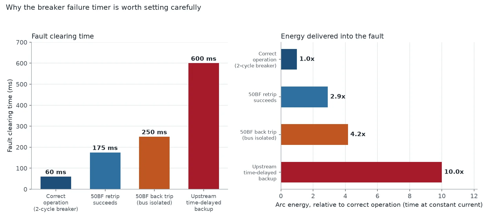
What makes 50BF hard is not the logic. It is the timing arithmetic, the current threshold, and the consequences of being wrong in either direction. Set it too slow and the fault burns for 600 ms instead of 60 ms. Set it too fast and a healthy bus trips because one current element had not reset. This article works through the actual numbers: the two conditions that must be met, the retrip and transfer trip sequence, the setting arithmetic from three real relay manuals, what 50BF cannot see, and what to write into a breaker specification so that the protection has something reliable to work with.
ANSI 50BF is not a single element. In practice it is a small logic block made of three parts, and confusing them is the source of most misapplications.
The function operates only when two conditions hold at the same time: a trip has been initiated, and current is still above the 50BF pickup after the timer expires. Trip alone is not enough, because a breaker that opened correctly would otherwise be declared failed every time a protection operated. Current alone is not enough either, because load current flows all day without any fault at all.
That AND gate is what separates 50BF from a plain time-delayed overcurrent relay. It is also why the function is sometimes called LBB, for local breaker backup: it is a backup that stays local, using the faulted bay’s own current measurement rather than reaching upstream to a distant relay that knows nothing about which breaker was supposed to operate.
A well-built scheme does not jump straight from “the breaker failed” to “trip the whole bus.” It escalates, and each step in the escalation has its own timer.
Retrip is the first stage. When the first timer expires, the scheme sends a second trip command to the same breaker, ideally through a second trip coil and a separate DC circuit. The purpose is narrow but valuable: a large share of real breaker failures are failures of the trip circuit rather than of the mechanism, and a second coil with its own wiring and its own fuse clears that class of failure without expanding the outage. Retrip is typically timed 50 to 120 ms after trip initiation.
Back trip is the second stage. If retrip did not work, the fault is not going to be cleared locally, so the adjacent breakers on the same bus must open to remove the infeed. This is the action that actually isolates the fault, and it is the one that determines the real cost of the event: every circuit on that bus loses supply. Back trip timing is typically 150 to 250 ms after initiation, and up to 400 ms where breaker operating times are slow.
Transfer trip is the optional third stage, used on lines. A faulted line whose local breaker is stuck still has a remote end feeding current into the fault through the line. Tripping the local bus does not stop that. A transfer trip or direct intertrip signal sent over the protection channel tells the remote terminal to open as well. Whether this stage exists is a scheme design decision, and on many sub-transmission lines it does not.
The three actions are not interchangeable, and a specification that says “breaker failure protection” without saying which of the three is required is an incomplete specification.
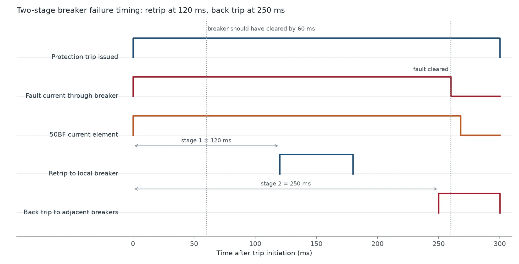
The 62BF setting is not a round number chosen by habit. It is the sum of everything that has to happen before failure can be declared, plus a margin. Three published examples show how similar the arithmetic is across manufacturers.
| Scheme | Stage 1 (retrip) | Stage 2 (back trip) | Terms included |
|---|---|---|---|
| Siemens 7SR105, HV breaker | 200 ms | 400 ms | Trip relay 10 ms + relay disengaging 50 ms + CB trip 80 ms + margin 60 ms |
| Siemens 7SR242 Duobias | 120 ms | 250–260 ms | Trip relay 10 ms + CB trip 50 ms + relay reset 30 ms + margin 30 ms |
| Siemens 7VK61 (two-stage) | 150 ms | 250 ms | T1 retrip, T2 back trip, both started at initiation |
Read the first row carefully, because it is the one that trips people up. The stage 2 timer is not stage 1 plus a bit. The second stage is built as its own sum that includes the first stage delay plus a second trip relay operation, a second breaker trip time, and a fresh margin. That is why the jump from 200 to 400 ms is larger than the 100 ms retrip window would suggest.
The general form is worth memorising:
TBF = trelay operate + tCB trip + trelay reset + margin
Two terms in that sum are routinely underestimated. The first is relay reset time: the 50BF current element does not drop out instantly when current stops, and a timer that ignores reset time will declare failure on a breaker that opened in 38 ms simply because the element had not released. The second is margin. A margin of 30 ms is tight. A margin of 50 to 60 ms is what most utilities specify for transmission-class breakers, and it is there to cover the tail of DC component, CT remanence, and the natural spread in mechanical operating time across a fleet of the same model.
The upper bound matters just as much as the lower bound. The 62BF timer must be shorter than the fastest upstream time-delayed backup protection that could otherwise clear the fault, with coordination margin left over. If the upstream distance zone 2 reaches 600 ms, a 250 ms back trip buys 350 ms of coordination room. If the upstream relay is set at 350 ms for some other reason, a 400 ms breaker failure setting will never operate first, and the scheme becomes decorative.
The single most common misconception about 50BF is that the current pickup should be set above the fault current. It should not. The element exists to detect the absence of current, so it is set as low as the measurement environment allows, subject to four constraints that pull in opposite directions.
| Constraint | Direction | Practical consequence |
|---|---|---|
| CT residual and saturation error | Raises the setting | Must sit above spurious secondary current during close-in external faults |
| Minimum load current | Raises the setting | The element must not be held in by normal load on a healthy feeder |
| Breaker residual current after opening | Raises the setting | Capacitive and resistive leakage must not hold the element up |
| Sensitivity to a genuine uncleared fault | Lowers the setting | A restriking or partially clearing breaker may carry little current |
The usual landing point is 0.2 to 0.3 times CT secondary rated current, which is the long-standing IEEE practice. Modern numerical relays can go lower, 0.1 to 0.5 times In, and many utilities use the lower end because the relay’s measurement is far more stable than an electromechanical element’s. Systems with very high fault levels sometimes push to 0.8 to 1.2 times In to stay clear of CT error during through-faults, accepting reduced sensitivity in exchange for security. Legacy 5 A secondary installations often sit at a flat 5 A.
One application breaks the rule entirely. On generator breakers, the current during a genuine failure can be a reverse-power condition of only 0.5 to 4 percent of rating, which is below any usable current threshold. There the scheme has to use the breaker’s 52a auxiliary contact as the failure criterion instead. That works, but it converts the function from a measurement-based check into a status-based one, and status contacts lie: a bent linkage or a sticky auxiliary switch will report the breaker open when it is closed. A 52a-only scheme is the weakest form of breaker failure protection and should be a deliberate, documented choice rather than a default.
On an effectively earthed network with single-pole auto-reclosing, 50BF cannot be a single three-phase function. It has to be pole-selective, and the reason is the dead time.
During a single-pole reclose cycle, one pole is open and two are carrying load. A three-phase current check would see load current on the healthy phases and interpret it as a failure, tripping the bus every time the line reclosed. The scheme must therefore evaluate each pole against its own current element, armed only for the pole that received a trip.
Two further interactions need to be checked at commissioning. First, the retrip stage must not be issued during the dead time of a normal reclose, because the breaker is supposed to be open; the scheme needs a reclose-blocking input or a timer that is reset by the reclose sequence. Second, if the breaker fails to open one pole and the protection trips three-phase, the resulting pole disagreement must be resolved before the back trip timer runs out, or the scheme will back trip for a condition that was actually a correct three-pole trip following a failed single-pole operation. The interaction between auto-reclosing logic and breaker failure timers is where most field misoperations in this function originate.
Twenty years ago 50BF was a dedicated relay in its own panel. Today it is almost always a function inside a multifunction protection relay, usually the same relay that provides the main protection for the bay. That is cheaper and simpler, and it introduces a coverage gap that is easy to miss.
If the breaker failure function is embedded in the line differential relay, and that relay is taken out of service for secondary testing, the bay loses both its main protection and its breaker failure coverage at the same time. Nothing on the panel says so. The standard remedy is procedural rather than technical: either extend the CT circuits and the trip circuits so that a separate relay carries 50BF for the zone, or require that the test procedure explicitly transfers the breaker failure function to a standby relay before the main relay is isolated. Writing that requirement into the station’s switching procedure is worth more than any setting refinement.
The other structural issue is CT placement. For the breaker failure function to see a fault that the breaker failed to clear, its current measurement must include every path that can feed the fault through that breaker. Where a bypass isolator or a busbar sectioning arrangement allows current to reach the bay from a direction the CTs do not cover, the function will be blind exactly when it is needed. On double-busbar arrangements this means CTs on both sides, or a scheme that combines the two measurements.
The interface with busbar protection in a high voltage substation deserves the same attention. Back trip is normally routed through the busbar protection’s lockout, not wired directly to each adjacent breaker, so that the busbar scheme’s own blocking and trip matrix stay consistent. Wiring 86BF straight to adjacent trip coils creates a second, uncoordinated trip path that will eventually operate during a busbar protection test.
Breaker failure is not one failure mode. The function’s value depends entirely on which mode is occurring, and there is a whole class of failures it handles poorly.
| Failure mode | Does 50BF catch it? | Why |
|---|---|---|
| Open trip coil, blown fuse, broken wiring | Yes | Current continues; retrip via second coil often clears it |
| Low station DC, charger failure | Yes | Same mechanism, but retrip will also fail — back trip is the only outcome |
| Mechanism jam, latch failure, disc spring breakage | Yes | Current continues until back trip |
| Contact welding after a high-current close | Yes | Current continues; the breaker is mechanically unable to open |
| SF6 pressure at lockout, trip blocked by pressure interlock | Yes, but late | The trip is electrically inhibited, so the failure is guaranteed, not intermittent |
| Slow opening, 90 ms instead of 45 ms | Only if the timer is tight | A generous margin hides degradation until the breaker is well past its limit |
| Breaker opens but does not interrupt (restrike, failure to clear) | Yes | Current persists through the arc; this is the case the current check was designed for |
| Failure of the 50BF function itself | No | Nothing supervises the supervisor |
The SF6 pressure case is worth dwelling on for anyone specifying breakers. A breaker at lockout pressure will not trip, by design, because opening at low density risks an internal flashover. That interlock is correct and it converts an electrical failure into a guaranteed breaker failure. The mitigation is not in the protection settings at all; it is in the gas density monitoring that should have alarmed hours earlier. A breaker with a temperature-compensated density relay that alarms well before lockout, and a maintenance regime that responds to the alarm, removes this failure mode from the 50BF statistics before it happens.
The bottom row of that table is the uncomfortable one. Breaker failure protection is the last line of defence, and there is no second line behind it. This is precisely why trip circuit supervision matters: a 74TCS scheme that monitors the trip coil continuously detects the open-coil failure in the days or weeks before a fault occurs, converting a bus trip into a work order. Breaker failure protection and trip circuit supervision are not alternatives. One is the alarm that prevents the event, the other is the response when prevention failed.
Dependability and security pull against each other here, and the asymmetry of the consequences is what should drive the choice.
Too slow, or not present. The fault is cleared by upstream time-delayed backup. On a typical distribution or sub-transmission coordination, that means 400 to 600 ms instead of 60 to 150 ms. The extra 400 ms of arcing is not a theoretical penalty: arc energy scales with time, so the equipment damage, the arc flash incident energy, and the probability of the fault escalating from a cable termination into a switchboard fire all rise roughly in proportion. Personnel in the vicinity are exposed for ten times longer. This is the case where the upstream breaker that eventually clears the fault also takes out every healthy circuit on its own bus, so the outage is larger than the failed breaker’s zone anyway.
Too fast, or too sensitive. A spurious back trip opens every breaker on the bus for a fault that one feeder’s breaker was about to clear correctly. On a transmission bus that is a multiple-circuit outage and possibly a stability event. It is also the failure mode that erodes trust in the scheme, and once operators start asking for 50BF to be switched off during certain conditions, the protection has negative value.
The asymmetry argues for a specific design posture: be generous with the margin, be careful with the current check, and make retrip do real work before back trip is allowed to fire. A scheme that reaches the bus trip 50 ms later than an aggressive one is not badly designed. A scheme that back trips once a year for no reason is.
Breaker failure protection is easy to set and hard to prove, because the function only does anything when something else has already gone wrong. Six checks are worth insisting on at commissioning.
A seventh check belongs to the maintenance cycle rather than commissioning: re-verify the 62BF timer after any breaker mechanism overhaul, because a mechanism that now trips in 65 ms instead of 45 ms has quietly eaten 20 ms of a 30 ms margin.
Protection engineers inherit whatever the breaker provides. Four breaker characteristics determine whether a good 50BF scheme is even possible, and all four belong in the technical specification rather than in a later negotiation.
Two independent trip coils, with separate wiring and separate fuses. Retrip only has value if the second path is genuinely independent. A second coil sharing the same terminal block and the same fuse is one coil with extra copper.
A full complement of auxiliary contacts, including changeover types. The scheme needs 52a and 52b for status and for trip circuit supervision, plus spare contacts for interlocking and for the station control system. Auxiliary contacts are cheap at order time and effectively impossible to add later without opening the mechanism.
A stated mechanical trip time, and a guarantee that it holds over life. The 62BF setting is built on the breaker’s operating time. A breaker specified at 50 ms that delivers 75 ms after ten years invalidates the arithmetic. Asking for the operating time to be stated in the type test report, and for the mechanism’s maintenance interval to be tied to it, is a reasonable request.
Gas density monitoring with an alarm stage well before lockout. As noted above, this is the one failure mode where protection cannot help, because the trip is inhibited by design. Products such as the LW36-126 for industrial power grid protection and the LW-252 50 kA split-type breaker are supplied with density relay contacts that can be wired to both alarm and lockout stages; how those contacts are used is a station design decision, but the contacts have to exist.
There is also a specification question that is rarely asked and should be: how fast is fast enough? The 62BF setting cannot be shorter than the breaker’s own clearing time plus margin, so a breaker with a 25 ms clearing time supports a 150 ms breaker failure setting that a 60 ms breaker cannot. Where the system needs the shorter number, the case for fast circuit breakers with half-cycle interruption is partly a breaker failure protection argument, not only a stability argument.
Breaker failure protection is a small amount of logic wrapped around a large amount of judgement. The judgement is in three places: the timer, which must be longer than the breaker’s worst honest performance and shorter than the upstream backup; the current check, which must be low enough to see a partially cleared fault and high enough to ignore CT error; and the escalation, which must give retrip a real chance before the bus is sacrificed.
None of that works if the breaker itself gives the scheme nothing to work with. Two trip coils, a full set of auxiliary contacts, an honest operating time and gas density contacts that alarm before they lock out are the four things that turn a protection setting into a protection scheme. If you are specifying breakers for a station where 50BF has to be dependable, review the SF6 breaker range and the auxiliary equipment options and put those four items in the technical data sheet before the commercial negotiation starts.
50BF is the current detector that decides whether the breaker actually interrupted; 62BF is the definite-time timer that decides when to declare failure. The function operates only when both agree: current still present after the timer expires. Some documents use 50BF for the whole function and 62BF for the timer alone, which is the source of most confusion.
150 to 250 ms for the back trip stage on transmission breakers, and 50 to 120 ms for the retrip stage. The setting is built as relay operating time plus breaker trip time plus relay reset time plus a 30 to 60 ms margin, and it must remain shorter than the fastest upstream time-delayed backup protection.
Because the element is looking for the absence of current, not the presence of a fault. A setting around 0.2 to 0.3 times CT rated current is typical: low enough to detect a breaker that only partially interrupted, high enough to stay above CT residual error and normal load current.
It can, using the 52a auxiliary contact as the criterion, but it is less secure because a bent linkage or sticky auxiliary switch can report the breaker open when it is closed. The 52a-only approach is normally reserved for generator breakers, where the current during a genuine failure may be only 0.5 to 4 percent of rating and below any usable current threshold.
Not necessarily, but embedding it in the main protection relay creates a coverage gap: when that relay is isolated for testing, the bay loses both main protection and breaker failure protection at once. Either provide a separate 50BF relay or write the function transfer into the switching procedure.
It forces the scheme to be pole-selective. During the dead time one pole is open and two carry load, so a three-phase current check would see load current and declare a failure on every reclose. The scheme must be armed only for the pole that received a trip, and the retrip timer must be reset or blocked by the reclose sequence.