Offshore Wind 66 kV Collection Systems: Breaker Selection for Salt Spray and Vibration
How 66 kV changed the collection system, what C5-M salt spray demands in measurable terms, and why the breaker boundary runs along the shoreline.
Read More
Most writing about IEC 61850 in high voltage switchgear is about the network. This one is about the other end of it: the terminals, contacts and coils on the breaker itself, because when a specification asks what an IEC 61850 circuit breaker interface must provide, these are the items that decide whether a digital substation project succeeds or stalls.
The promise is straightforward. Replace hundreds of copper cores running from the switchyard to the protection and control room with a handful of fibres, digitise current and voltage at the source, and send trip commands as Ethernet frames that arrive in three milliseconds. ABB’s own engineering review puts the copper reduction at up to 80 percent, and several utilities report project-level savings in the 20 to 25 percent range.
What that summary leaves out is that the breaker does not become digital. It still has a mechanism, a trip coil, auxiliary contacts, a density relay and an anti-pumping relay, and every one of those still has to be wired to something. A digital substation does not remove the interface; it moves it, and in moving it changes what the interface has to be able to do.
This article works through the standard’s three communication services, the real time budget for a GOOSE trip, the sampled value rates that replaced the old 80-samples-per-cycle rule, and then the part that matters for anyone buying breakers: which functions must stay hardwired no matter how digital the station becomes, and what to write into the technical specification.
IEC 61850 is not one protocol. It is a data model plus three distinct communication services, and each replaces a different bundle of copper.
| Service | Layer and mechanism | What it replaces | Latency target |
|---|---|---|---|
| MMS | Client-server over TCP/IP, port 102 | SCADA point-to-point wiring and proprietary polled protocols | Tens to hundreds of ms, not time critical |
| GOOSE | Layer 2 Ethernet, EtherType 0x88B8, publisher-subscriber multicast | Hardwired trip, interlock, blocking and status signals between IEDs | 3 ms at performance class P2/P3, 10 ms at P1 |
| Sampled Values | Layer 2 Ethernet, EtherType 0x88BA, publisher-subscriber multicast | Copper CT and VT secondary circuits from the switchyard | 3 ms transfer, one frame every 250 µs |
The distinction that trips up project teams is routability. GOOSE and Sampled Values are Layer 2 multicast frames. They do not route, they do not cross a router, and they stay inside one Layer 2 domain, separated by VLAN tags with IEEE 802.1Q priority. MMS, by contrast, is ordinary TCP/IP and can leave the station. The routable variants R-GOOSE and R-SV exist under IEC 61850-90-5, but they are for wide-area applications, not for tripping a breaker twenty metres away.
The data model on top of these services is what makes interoperability possible. A breaker is not a list of registers; it is a logical node XCBR with a position data object, and the object reference Bay1/XCBR1.Pos.stVal means the same thing in every vendor’s implementation. That is the actual value of the standard, and it is also the reason the SCL engineering workflow (ICD, SSD, SCD, CID files under IEC 61850-6) exists and takes longer than anybody budgets for.
Performance classes make the requirement concrete. A type 1A message, which is a trip, must arrive within 10 ms under class P1 and within 3 ms under P2/P3. Distribution substations are usually specified to P1; transmission substations to P2/P3. IEC 61850-5 allocates that budget: 20 percent to network latency, 40 percent each to sender and receiver processing, which leaves roughly 600 µs of actual network transfer time for a trip frame.
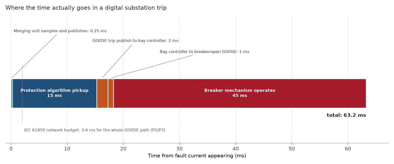
That sounds tight until you put it next to the rest of the trip path, where the network turns out to be the smallest term.
| Stage | Typical duration | Dominated by |
|---|---|---|
| Merging unit samples and publishes | 0–0.25 ms | One sample period at 4 kHz |
| Protection algorithm pickup | 8–20 ms | Half cycle to one cycle of filtering |
| GOOSE trip publish to bay controller receive | 0.5–2 ms | Switch hops, strict-priority queuing |
| Bay controller to breaker-open GOOSE | 0.5–1 ms | Second hop, plus output relay |
| Breaker mechanism operates | 30–60 ms | Mechanical energy, not electronics |
Read the last row again. The breaker’s own operating time is between fifteen and sixty times the network transfer time it is often blamed for. A project that spends months optimising switch configuration to shave 500 µs off GOOSE while accepting a 60 ms breaker has optimised the wrong term.
This is not an argument against digital substations. It is an argument for buying the breaker on its operating time rather than treating the protection and control layer as the performance bottleneck. Where fault clearance time is the binding constraint, the 25 ms class of fast circuit breakers buys more than any network tuning can.
Almost every article on digital substations quotes 80 samples per cycle. That number comes from the UCA International Users Group implementation guideline known as 9-2LE, not from IEC 61850-9-2 itself, and the distinction now matters because newer projects specify something different.
| Specification | Protection rate | Measurement / PQ rate | Notes |
|---|---|---|---|
| UCA 9-2LE guideline | 80 samples per cycle (4000/s at 50 Hz) | 256 samples per cycle | Still the dominant profile in service |
| IEC 61869-9 | 4800 samples per second | 14 400 samples per second for power quality | Fixed rates, independent of 50 or 60 Hz |
The practical consequence is that a merging unit must publish a frame every 250 µs at 4 kHz. Measurement samples are batched, typically eight at a time, so a measurement frame appears every 625 µs. Every switch in the path must forward those frames with essentially no loss and negligible queuing delay.
Then there is the part that has nothing to do with communication and everything to do with physics. Samples from different merging units are only comparable if they are taken at the same instant, which means time synchronisation to about one microsecond using PTP under the power utility profile IEC/IEEE 61850-9-3. Without it, phase angles from two merging units do not add up, and any function that subtracts one current from another stops being meaningful.
For the breaker, this changes the instrument transformer conversation. A conventional CT with a standalone merging unit bolted next to it is the low-risk path, and it is the one most retrofits take. A non-conventional instrument transformer with a digital output removes the core and therefore removes saturation as a failure mode, but it moves the accuracy question into the electronics and the time alignment. Either way, the CT ratio and class decisions described in the guide to bushing current transformers in dead-tank breakers still apply; only the medium carrying the secondary current changes.
This is the section that digital substation literature usually skips, and it is the one that determines whether the station is safe. Moving the interface onto Ethernet does not move these functions off the breaker.
Auxiliary contacts are still physical. The position indication published as XCBR.Pos comes from a contact on the mechanism. That contact is also what the trip circuit supervision scheme monitors, what the disconnector interlock uses, and what the breaker failure current check falls back on when current measurement is unavailable. GOOSE carries the status; it does not create it.
Trip circuit supervision is still required. A GOOSE subscription supervises itself: every publisher retransmits continuously, fast after a change and then backing off to a heartbeat, and every message declares when the next one is due. If the publisher stops, the subscriber knows within a defined interval. What that does not cover is the last metre — the output relay, the terminal block, the trip coil, the auxiliary switch in the trip circuit. A trip circuit supervision scheme monitoring the coil itself is still the only thing that detects an open coil, and digital substations do not remove the need for it.
Two trip coils, still. The redundancy argument does not weaken in a digital station; if anything it strengthens, because the trip path now has more components that can fail. A second coil with its own wiring, its own MCB and its own output relay from a different IED is what makes retrip meaningful in breaker failure protection schemes.
Anti-pumping stays in the mechanism box. Anti-pumping is a hardwired electrical interlock between the close circuit and the breaker’s own closed position. It must not depend on a network message arriving. Every specification should state that the anti-pumping relay is part of the breaker, not part of the bay controller logic.
Gas density lockout stays hardwired. The SF6 density relay has two stages, alarm and lockout, and the lockout stage physically inhibits tripping and closing to prevent an internal flashover at low density. Routing that inhibit through a GOOSE message would put a safety interlock behind a network. It stays a hardwired contact in series with the trip circuit, and the digital system only receives a copy for alarm and logging. A temperature-compensated density relay with independent alarm and lockout contacts is therefore still a required item, and the contacts still have to be wired.
Local control stays local. The local/remote selector, the local trip pushbutton and the mechanical trip and close controls exist for the person standing in front of the breaker when the network is down. They are not optional in a digital station; they are the reason the station can be operated when the station bus has failed.
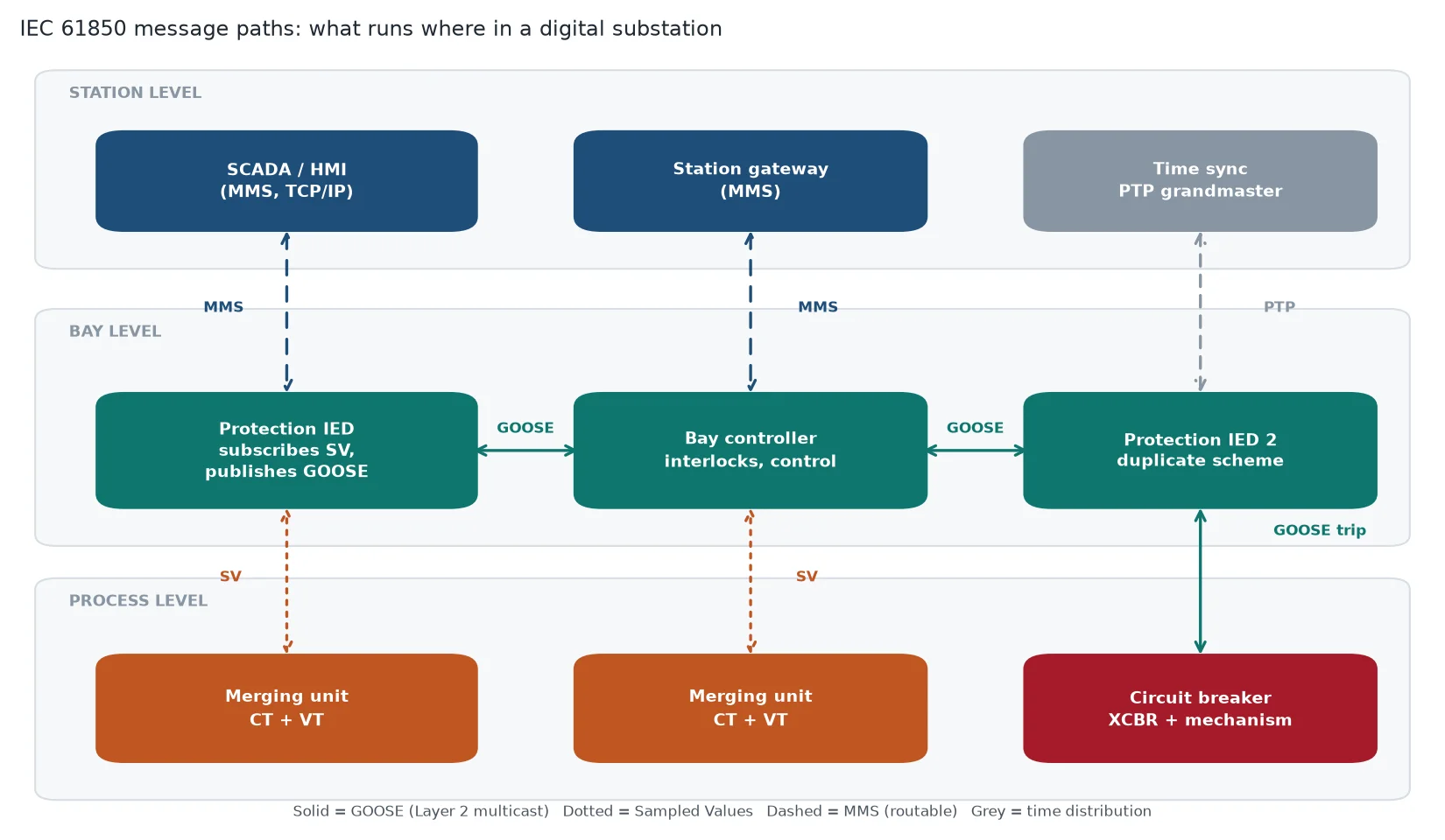
A protection scheme cannot ride through the reconvergence delay of a spanning tree protocol, so the two buses are built differently from an ordinary office network.
IEC 62439-3 defines two mechanisms, PRP and HSR, and both duplicate every frame over separate paths so that a single fault causes no recovery time at all. In practice they land in different places. PRP suits the station bus, where servers and gateways sit behind switches on two independent LANs. HSR rings suit bay and process level, where merging units and relays each have two Ethernet ports and are naturally strung in a loop, typically one ring per bay. A RedBox bridges an HSR ring into a PRP network where the two meet. RSTP is acceptable at station level in simple installations and unacceptable on a process bus, where a few tens of milliseconds of reconvergence is longer than the entire protection budget.
Time distribution gets the same treatment. PTP travels in band, from a GNSS-disciplined grandmaster attached to the station bus as an ordinary dual-attached device. There is no dedicated timing cable to every relay, which is what IRIG-B and 1 PPS required, and the cost of that convenience is that every switch on the path must handle the profile correctly as a boundary or transparent clock. A switch that forwards PTP frames without correcting for its own residence time will silently destroy the accuracy budget, and nothing will alarm until a differential function starts producing unexplained operations.
Digital substations fail differently from conventional ones, and three of the differences are worth designing for explicitly.
Sampled values stop. A relay fed by sampled values has no analog input to fall back on. If the stream stops, or if the quality attribute on the data goes invalid, the affected protection function must block and alarm rather than operate on stale samples. That is the correct behaviour, and it means the station loses protection for that bay until the stream returns. The design question is how quickly the operator finds out and what the fallback is.
Synchronisation degrades. Each sampled value stream carries an indicator of whether its samples are aligned to a global clock, a local clock, or nothing. Functions that compare measurements across merging units — busbar differential, line differential — depend on that alignment and have to react when it is lost. Functions working from a single merging unit, such as overcurrent, are much less exposed. Deciding what each function does when synchronisation degrades is a protection design decision, not a network one, and it belongs in the settings file rather than in the commissioning report.
The engineering is the risk, not the hardware. SCL dialects differ between vendors, and the configuration work of merging ICD files into an SCD and producing per-IED CID files is where schedules slip. Cyber security is the other one: an Ethernet-connected substation needs IEC 62351 for the protocol layer and IEC 62443 for the system, and both add documentation that has to exist before energisation.
Almost no utility replaces a working secondary system in one step. The pattern that has held up in practice is two-phase.
Phase one puts the station bus in: IEDs, gateway, HMI and SCADA on IEC 61850 MMS, with GOOSE used for interlocks and blocking between bays. The switchyard copper is untouched, protection is unchanged, and the benefit is engineering and data, not wiring. Phase two puts the process bus in, bay by bay, with a standalone merging unit installed beside each existing conventional CT and VT. Fibre replaces the copper from the marshalling kiosk to the relay, and the instrument transformers stay.
ABB’s first commercial IEC 61850-9-2 installation followed exactly this logic: Loganlea for Powerlink Queensland in 2011, as an upgrade of an existing station rather than a greenfield build, with a retrofit specification that was then reused at Millmerran in 2013 and Bulli Creek in 2014. The reported saving from utilities that have done it is consistent: around 20 percent of project cost from process bus topology in one transmission study, 25 percent at an Australian switching substation, and in a European 400/132 kV modernisation, a 70 percent reduction in copper cabling worth over a million dollars in material and labour, with engineering time on later bay additions down by roughly 40 percent because the SCL templates were reusable.
Those numbers are real, and they are not primarily about cable cost. They are about trenching, terminations, testing hours, fault finding in a thousand-core marshalling box, and the fact that fibre does not propagate fire and cannot deliver a high voltage onto a terminal someone is touching.
If the station is going digital, the breaker’s technical data sheet should say so. These items are cheap at order time and expensive to retrofit.
| Item | Requirement | Why it matters in a digital station |
|---|---|---|
| Trip coils | Two, independent wiring and independent MCBs | Retrip and redundant GOOSE paths need separate physical endpoints |
| Auxiliary contacts | Minimum two changeover 52a/52b pairs plus spares | Position, TCS, interlock and breaker failure status all read from these |
| Anti-pumping | Integral to the mechanism, hardwired | Must not depend on a network message |
| Density relay | Independent alarm and lockout contacts, cabled out | Lockout stays hardwired; digital system takes a copy only |
| Local control | Local/remote selector, local trip and close, mechanical indicators | Only operable path when the station bus is down |
| Test facilities | Test switch or test terminal block per trip circuit, CT shorting facility | Secondary injection without disturbing the process bus |
| Operating time | Stated in the type test report, guaranteed over life | The dominant term in the total trip time, and the basis of the breaker failure setting |
| Condition monitoring | Travel curve, gas density and coil current available as signals | Feeds the maintenance strategy that a digital station makes possible |
Two of those rows are worth arguing about in the commercial negotiation rather than accepting by default. Auxiliary contact count is the one item that engineers most often wish they had specified higher, because every digital function wants a contact and the changeover types are the ones that matter. Operating time is the other: a breaker with a stated 50 ms that delivers 75 ms after ten years quietly invalidates a breaker failure setting that was calculated on the original figure.
IEC 61850 does not make a breaker digital. It moves the interface, digitises the measurements, and replaces a bundle of copper trip cores with a supervised multicast frame that arrives in three milliseconds. Everything mechanical, magnetic and pneumatic stays exactly where it was, and the functions that protect people — anti-pumping, density lockout, local trip — stay hardwired because they have to work when the network does not.
That is the practical test for any digital substation specification: for each signal, ask what happens when the station bus is down. If the answer is that the breaker can still be tripped locally, the density interlock still inhibits, and the anti-pumping relay still works, the design is sound. If any of those answers depends on a message, it needs rewiring.
If you are building out a station where the breaker has to carry this interface reliably for thirty years, the LW-252 customized outdoor breaker is supplied with dual trip coils, a full auxiliary contact complement and cabled-out density relay contacts as standard configuration items rather than options. Start the conversation with the interface requirements and the electrical ratings follow.
No. The position published as XCBR.Pos is derived from a physical auxiliary contact on the mechanism. That contact also feeds trip circuit supervision, the disconnector interlock and the breaker failure status check. GOOSE carries the status; it does not generate it.
GOOSE carries binary events such as trips, interlocks and blocking signals between IEDs, with a 3 ms transfer target at performance class P2/P3. Sampled Values carries digitised current and voltage from a merging unit, one frame every 250 µs at 4 kHz. Both are Layer 2 multicast and neither is routable.
The widely quoted 80 samples per cycle comes from the UCA 9-2LE implementation guideline, which gives 4000 samples per second at 50 Hz. Newer projects increasingly reference IEC 61869-9, which specifies 4800 samples per second for protection and measurement and 14 400 for power quality, at both 50 and 60 Hz.
Yes, and it does, using GOOSE. What it must not do is route safety interlocks over that network. Anti-pumping, gas density lockout and local trip remain hardwired, and the trip coil itself is still supervised by a conventional trip circuit supervision scheme.
Sampled values carry a synchronisation indicator. Functions that compare measurements from more than one merging unit, such as busbar or line differential, depend on that alignment and must block or alarm when it is lost. Functions using a single merging unit, such as overcurrent, are far less exposed.
Usually, but not because of the cable. Reported savings are around 20 percent of project cost from process bus topology, up to 25 percent at some switching substations, and up to 80 percent less copper. The larger recurring saving is in engineering time on later bay additions, once the SCL templates are reusable.