Offshore Wind 66 kV Collection Systems: Breaker Selection for Salt Spray and Vibration
How 66 kV changed the collection system, what C5-M salt spray demands in measurable terms, and why the breaker boundary runs along the shoreline.
Read More
A fast circuit breaker is one that clears a fault in roughly 25 milliseconds instead of the two to three cycles — 40 to 60 ms — that a conventional high-voltage breaker needs. The distinction sounds like an exercise in rounding, but at transmission level it is the difference between a system that rides through the disturbance and one that loses synchronism, between a transformer that sees one half-cycle of fault current and one that sees three, and between a corridor that can be uprated in software and one that needs new lines. Chinese manufacturers including Pinggao and Taikai have demonstrated 550 kV fast breakers with total clearing times near 25 ms and contact part times around 8 ms, and the technology is now a live option in specifications rather than a research topic.
But a fast breaker is not a free upgrade. It changes the duty on the interrupter, it shifts where the milliseconds in the protection chain actually go, and it costs real money in actuator complexity. This article walks through where the time is spent in a clearing operation, how an 8 ms contact part is achieved and what it does to the mechanism, why interrupting earlier raises the transient recovery voltage demand rather than lowering it, and — most usefully — a framework for deciding whether your project actually needs one. If you are comparing high-voltage SF6 circuit breakers for a substation where fault clearing time is being challenged, this is the arithmetic behind the sales claim.
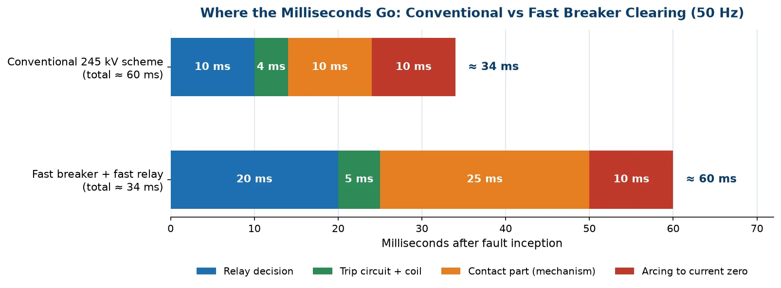
Total fault clearing time is the sum of four intervals, and only one of them belongs to the breaker. Relay operating time is typically 15 ms to 25 ms for a transmission protection scheme, trip circuit and coil response adds 3 ms to 8 ms, mechanical contact part takes 20 ms to 35 ms on a conventional breaker, and the arcing time until current zero adds up to half a cycle — 10 ms at 50 Hz, worst case, with a mean of about 5 ms.
Add those up and a conventional 245 kV installation clears in 45 ms to 60 ms. Breaker manufacturers who quote “two cycles” or “40 ms” are quoting the breaker’s own rated interrupting time per IEC 62271-100, not the system clearing time. This is the first thing to pin down in any conversation about speed, because a vendor offering a 25 ms breaker into a scheme with a 25 ms relay still produces a 50 ms system — no faster than the conventional breaker it replaces.
| Interval | Conventional 245 kV scheme | Fast breaker + conventional relay | Fast breaker + fast relay |
|---|---|---|---|
| Relay decision time | 15 – 25 ms | 15 – 25 ms | 8 – 12 ms |
| Trip circuit and coil | 3 – 8 ms | 3 – 8 ms | 3 – 5 ms |
| Contact part (mechanism) | 20 – 30 ms | 8 – 12 ms | 8 – 12 ms |
| Arcing to current zero | 0 – 10 ms | 0 – 10 ms | 0 – 10 ms |
| Total clearing | 40 – 70 ms | 28 – 55 ms | 20 – 39 ms |
The table explains why the serious fast-breaker projects are always protection modernisation projects. Half-cycle interruption — a true 10 ms clearing at 50 Hz — requires the relay, the trip path and the mechanism to be redesigned together. Buying the breaker alone buys perhaps a third of the available improvement.
A conventional spring or hydraulic mechanism accelerates a mass of several hundred kilograms through a 150 mm to 250 mm stroke, and the physics of that mass limits the acceleration to roughly 2 g to 4 g. Contact part therefore arrives 20 ms to 30 ms after the trip coil is energised, no matter how the rest of the scheme is tuned.
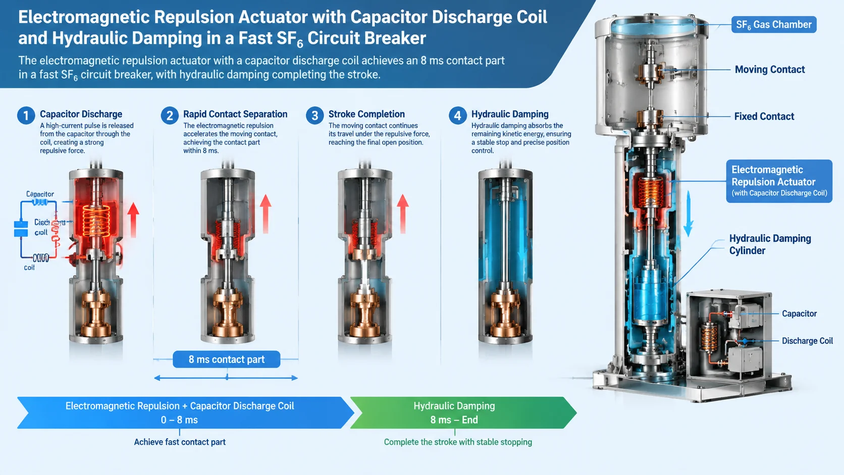
The technology behind the 8 ms figures is an electromagnetic repulsion actuator: a flat coil carrying a capacitor discharge, opposed by a conducting disc coupled to the moving contact. The current in the coil induces an opposing current in the disc, and the two repel with a force that reaches hundreds of kilonewtons for a few milliseconds — enough to accelerate the contact to several hundred g. The contact parts within 4 ms to 8 ms, the capacitor bank is discharged, and a conventional hydraulic or spring system takes over to complete the stroke, hold the open gap and reset for the next operation.
This hybrid arrangement — repulsion for the first few milliseconds, conventional energy storage for the rest — is what makes the concept practical. A pure repulsion system would need an enormous capacitor bank to deliver the full stroke, and it would have no way to hold the breaker open or to close it. The hybrid keeps the fast physics where it pays (getting the contacts apart before the fault current reaches its first major peak) and leaves the slow physics to mature hardware.
Accelerating contact mass at several hundred g concentrates mechanical stress in the disc, the coupling and the first part of the transmission linkage. Damping the resulting travel is not trivial — the travel curve of a fast breaker shows the same velocity, overtravel and rebound features as a conventional one, but compressed into a quarter of the time, and damping element wear becomes a genuine maintenance item rather than a footnote. The operating mechanism comparison in our library covers the conventional options; a fast breaker adds a fourth subsystem — capacitor charging supply, control electronics and the repulsion coil itself — each of which needs its own surveillance. For an engineer assessing lifecycle cost, the honest statement is that the mechanism is where both the performance and the maintenance burden live.
Intuitively, clearing a fault sooner should be easier on the breaker — less arc energy, less contact erosion, less gas heating. For arc energy that is true. But there is a second-order effect that works the other way, and it is the main technical risk in a fast-breaker application.
A fault current waveform is roughly sinusoidal with a decaying DC component. Interrupt at the natural current zero of a two-cycle clearing and the current is near its slowest rate of change. Interrupt one full cycle earlier — as a 25 ms scheme does — and you are interrupting at a point where di/dt at current zero is higher. The rate of rise of recovery voltage (RRRV) scales with di/dt, so the interrupter faces a steeper transient recovery voltage for the same short-circuit current.
The IEC 62271-100 TRV envelopes were drawn around conventional clearing times. A breaker that interrupts significantly earlier than the standard test duties assume may face RRRV values above the envelope, particularly on short-line fault duties, where the line-side sawtooth component is superimposed on the source-side transient and the initial RRRV is already the most severe case in the standard. The practical consequence for a buyer is simple: when you specify fast clearing, you must also specify the TRV conditions at your busbar, and ask the manufacturer to demonstrate the interrupter handles the earlier current zero. A supplier who answers that question with the standard type-test certificate has not answered it.
| Parameter | Effect of faster clearing | What to check |
|---|---|---|
| Arc energy per operation | Lower — shorter arcing time | Interrupter contact life improves |
| di/dt at current zero | Higher — earlier zero crossing | RRRV capability versus IEC envelope |
| Short-line fault severity | Higher initial RRRV | L90/L75 test evidence at the faster timing |
| Let-through I²t | Lower — the whole point of the exercise | Transformer, cable and CT thermal margins |
| Transient stability margin | Higher critical clearing time margin | System study, not a nameplate number |
Four benefits justify the technology, and they have very different values depending on the project.
Fault current in an inductive network does not reach its prospective peak instantly; it takes one to two cycles depending on the DC time constant, which at transmission level is typically 45 ms. A conventional breaker with 40 ms to 60 ms clearing watches the fault current climb to its full asymmetric peak. A 25 ms breaker interrupts before the peak arrives, so transformers, cables, busbars and CTs never see the worst-case mechanical and thermal stress. In networks where the fault level has grown towards equipment ratings — a common situation in dense industrial grids and metropolitan transmission — this is often the decisive benefit, because it can defer an entire reinforcement programme. Where the calculation gets tight, the 252 kV 50 kA split-type class is usually the reference point for how much breaking capacity is already available before speed has to do the work.
The critical clearing time of a transmission corridor — the longest fault a system can survive without losing synchronism — is set by the inertia of the machines and the impedance of the network. As corridors are loaded closer to their limits, the margin between the actual clearing time and the critical clearing time narrows. Reducing clearing from 60 ms to 30 ms on a heavily loaded corridor can raise the transfer limit by several percent, which on a 500 kV interconnector is worth more per year than the breakers cost. This is the application where fast breakers genuinely pay for themselves, and it is why the first commercial installations are on high-value transmission corridors rather than ordinary substations.
Sensitive industrial loads — semiconductor fabs, data centre UPS systems, paper machines — ride through sags of up to 100 ms to 200 ms but trip on deeper or longer disturbances. Clearing in 25 ms instead of 60 ms cuts the sag depth and duration substantially, and for a plant where one excursion costs more than the breaker, the business case closes quickly. Data centre operators evaluating their incoming supply now ask about clearing time explicitly, and the 126 kV 40 kA class at the substation interface is where the answer usually has to come from.
Incident energy in an arc flash event scales linearly with time. Reducing the clearing time from 60 ms to 25 ms cuts the energy by more than half, which changes the PPE category, the arc flash boundary and the maintenance approach around the equipment. At transmission voltages this matters less — arc flash is primarily an enclosed-switchgear concern — but at the medium-voltage end of a fast scheme, where the same protection philosophy applies, it is a real occupational safety benefit and increasingly cited in specifications.
The counterlist is just as concrete, and an honest assessment saves a buyer from paying for performance the scheme cannot use.
Feeders where protection coordination governs. If the upstream-downstream coordination relies on time-graded protection, a faster breaker simply shifts the whole coordination chain and may require re-verification of every relay setting. The system gets faster only if the slowest device in the chain was the breaker — which it rarely is at distribution level.
Installations with comfortable fault margins. If the prospective fault current sits at half the equipment rating and the corridor is nowhere near its stability limit, 25 ms buys nothing that 60 ms does not already deliver. This is the majority of installations, and it is the reason fast breakers are a specialist product rather than a default.
Schemes with legacy relays. As the timing table showed, the relay dominates the total. Spending on the mechanism while keeping a 25 ms electromechanical protection chain yields a scheme that is barely faster overall — and considerably more expensive.
Applications where the breaker already operates frequently. Fast actuators add subsystems that need surveillance. On a breaker that switches daily — a railway feeder, an arc furnace supply — the added failure modes deserve a second look before the speed benefit is banked. For those duties the endurance and maintenance side matters more, which is the subject of our endurance class and maintenance guides.
Fast breakers cost more, and it is worth understanding where the money goes, because that is where the negotiation happens.
| Cost element | Why it exists | Negotiable? |
|---|---|---|
| Repulsion actuator and capacitor bank | The core of the 8 ms contact part; cannot be value-engineered out | No |
| Capacitor charging and control electronics | Charges and monitors the discharge bank; adds surveillance scope | Scope, not presence |
| Damping and travel control hardware | Controls the energy of a several-hundred-g acceleration | Limited |
| Type test extension | Demonstrating TRV capability at earlier current zeros | Yes — share your busbar TRV data early |
| Protection scheme upgrade | Relay and trip path must match the breaker to realise the benefit | Outside the breaker contract — budget it separately |
The last row is the one that ambushes budgets. A fast breaker project that does not include protection modernisation is half a project, and the half that is missing is usually the cheaper half per millisecond gained.
The specification line that makes a fast-breaker enquiry meaningful is not “25 ms clearing”. It is a statement of what the 25 ms is for, plus the scheme data needed to verify it:
A manufacturer who receives that list can answer with a real design. One who receives “25 ms breaker, 40 kA” will answer with a catalogue page. Where the application sits at the top of the voltage range, the 252 kV customised configuration is the natural starting point for that conversation, because the interrupter and mechanism combination is configured to the scheme rather than selected from stock — which is exactly what a fast-breaker application requires.
The wider context of what a breaker must survive — the test duties, the endurance classes, the switching duties that sit alongside fault clearing — is collected in the SF6 circuit breaker technical library, and the IEC 62271-100 framework behind those tests is set out in our standards guide.
No. A 25 ms total clearing time at 50 Hz is about 1.25 cycles. Half-cycle interruption — 10 ms — is the next step beyond that and requires the relay, trip path and mechanism to be co-designed; current commercial fast breakers target the 20 ms to 30 ms range for total system clearing, with the breaker’s own interrupting time in the 12 ms to 20 ms window.
You need a relay faster than about 15 ms to realise most of the benefit. With a conventional 20 ms to 25 ms relay, the scheme total improves from roughly 55 ms to roughly 40 ms — worthwhile but well short of the 25 ms headline. The mechanism and the protection must be specified together.
Arc energy per operation drops, which helps the contacts. But the duty shifts towards higher RRRV at current zero, which is harder on the interrupter’s dielectric recovery, and the mechanism itself works harder at higher acceleration. Overall wear is not simply better or worse — it moves to different components, and the maintenance plan has to follow.
Not in any meaningful sense. The repulsion actuator, its capacitor bank, the damping system and the control electronics are designed into the mechanism architecture. Some manufacturers offer actuator upgrades within a product family, but a generic retrofit to an arbitrary installed breaker is not a real product — treat any vendor claiming otherwise with caution.
Ask for the TRV capability at the earlier current zero, evidenced by test reports at the fast timings rather than the conventional ones. If the answer is the standard type-test certificate, the breaker has not been demonstrated for your duty, however impressive the millisecond figure.
The technology is most mature at 245 kV to 550 kV, where the stability and fault-level arguments are strongest. At 126 kV and below the same clearing-time benefits are achievable more economically with faster protection relays and conventional breakers, and that is usually the better engineering answer for distribution-level installations.