Offshore Wind 66 kV Collection Systems: Breaker Selection for Salt Spray and Vibration
How 66 kV changed the collection system, what C5-M salt spray demands in measurable terms, and why the breaker boundary runs along the shoreline.
Read More
A breaker that opens with no fault on the system is one of the most corrosive failures in a substation. Nothing is damaged, no protection flag is raised, and the feeder simply goes dark. Operators reset it, it holds, and everyone moves on — until it happens again at three in the morning on a circuit that matters. Circuit breaker tripping without fault almost never means the protection relay misjudged the primary current. It means something in the trip circuit delivered a command nobody issued, or the mechanism released itself.
That distinction is the whole diagnosis. A genuine fault produces evidence: current, a relay target, an event record, a disturbance file. A spurious trip produces a breaker in the open position and an empty event log. This guide builds the five-cause tree that covers nearly every case, walks through the DC earth mechanism that causes the majority of them, covers vibration, EMI and anti-pumping failures, and gives a 30-minute triage sequence you can run before the trail goes cold. It assumes the high voltage SF6 circuit breaker itself is healthy until the evidence says otherwise — which is usually the right order.
Before touching anything, establish whether the trip was commanded or parasitic. Read the relay event record, not the alarm list. A commanded trip leaves a pickup, a trip decision and a timestamp that precedes the breaker’s open indication by a plausible interval. A parasitic trip leaves the relay with no pickup at all, or with a pickup that never reached a trip threshold.
If the relay shows no operation, the trip bus was energised by something downstream of it: a second earth on the DC system, an induced voltage on a control cable, a chattering auxiliary contact, a welded relay contact, or a mechanism that released on its own. Those five possibilities are the tree.
There is a sixth case that masquerades as a spurious trip and should be ruled out early: a protection operation caused by a secondary circuit problem rather than a primary fault. A CT secondary open circuit, a VT fuse failure, or a sampled value channel with a corrupted signal can all produce a genuine relay operation on a healthy feeder. The event record will show the operation, but the currents will not reconcile with the primary plant. That case belongs in a different investigation, and the broader diagnostic map is in this guide to SF6 circuit breaker failure and troubleshooting.
| Cause | Mechanism | Fastest discriminator |
|---|---|---|
| DC earth fault (two-point) | A second earth on the opposite pole completes a path through the trip coil | Pole-to-earth voltage on the DC bus is unbalanced; insulation monitor alarmed |
| EMI on control wiring | Induced transient on an unshielded or single-ended shielded trip conductor | Trip repeats after nearby switching operations, never during quiet periods |
| Vibration and contact chatter | Auxiliary contact or electromechanical relay momentarily makes the trip path | Trip follows breaker operation, heavy traffic, or mechanical work nearby |
| Anti-pumping circuit failure | Close circuit stays live, breaker closes into a trip and repeats | Breaker pumps — multiple close-open cycles per command |
| Mechanism self-release | Latch engagement worn, spring charge low, hydraulic pressure transient, foreign object | Breaker opens with DC control supply isolated |
The last row is the one that separates mechanism from control. If the breaker opens with the control supply isolated and the trip coil disconnected, no amount of circuit analysis will explain it, because the release was mechanical. That single test saves more time than any other in this list.
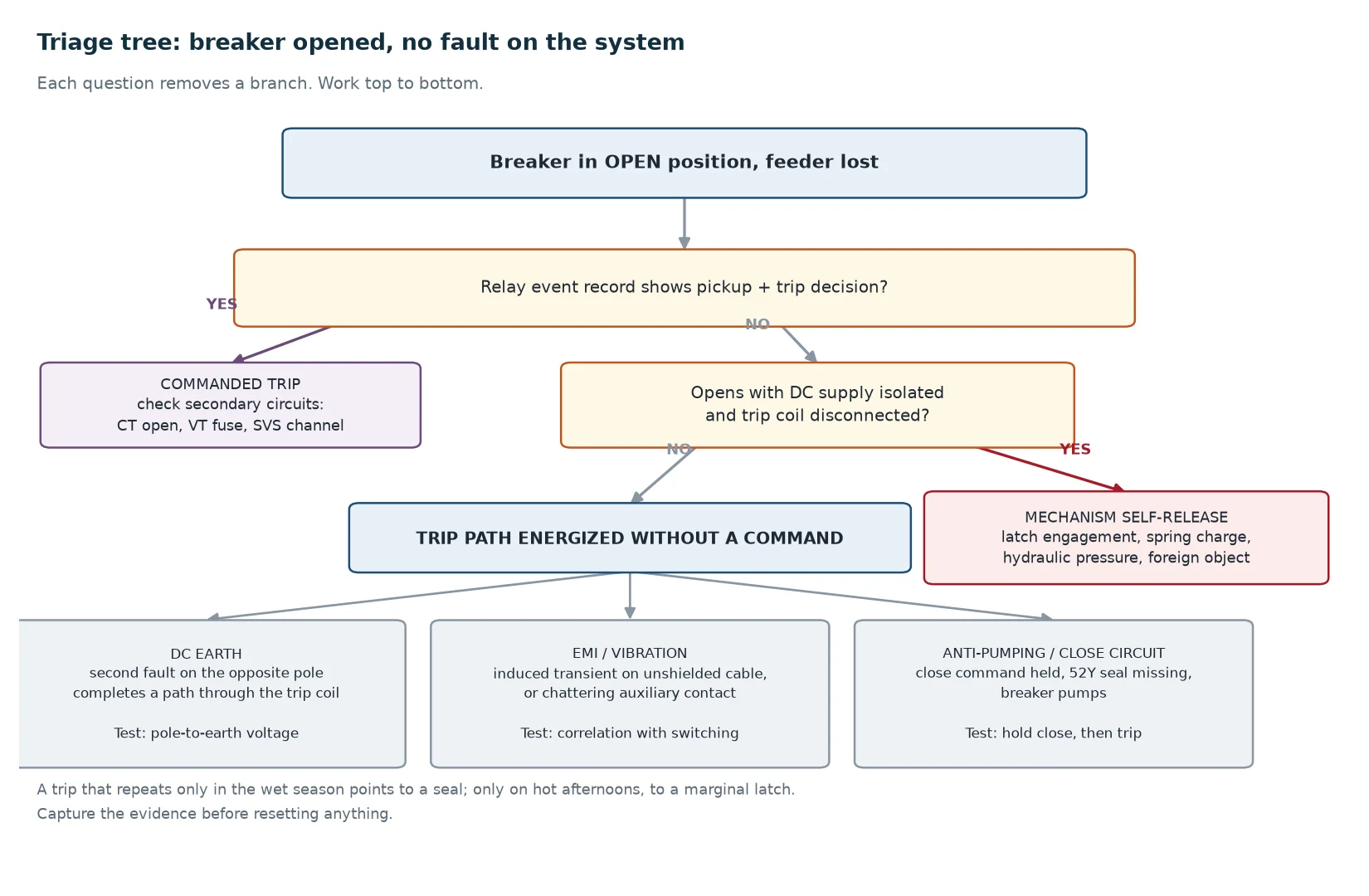
Most substation DC systems are deliberately unearthed. Neither pole is bonded to earth, so a single insulation defect connects one point of the DC network to earth without completing a circuit. No current flows, nothing operates, and the insulation monitoring device raises an alarm that is easy to defer.
That first fault is harmless and it is also the setup. With one pole already tied to earth, a second fault on the opposite pole anywhere in the scheme completes a path nobody drew. If the first fault sits on the positive bus and the second lands on the negative side of a trip coil, current flows from the positive bus, through earth, into the trip coil’s negative terminal, and the coil energises. The breaker opens. No protection operated, because no protection was involved.
The same pair of faults can also cause the opposite failure. If both faults sit across the coil or across a critical control element, they short it out, and the breaker refuses to trip when a real command arrives. That is the more dangerous outcome, and it is why a standing DC earth alarm is a defect rather than a nuisance.
Measure the voltage from each pole to earth. On a healthy floating system with balanced leakage, both readings sit near half the bank voltage with opposite polarity. When one pole is faulted to earth, its reading collapses toward zero and the opposite pole climbs toward the full bank voltage. That tells you immediately which pole is involved, without opening a single circuit.
Treat the absolute values as indicative rather than exact. What a voltmeter displays depends on its own input impedance and on any reference resistors in the scheme, so two instruments can disagree honestly about the same healthy system. For a 110 V DC system, normal pole-to-earth insulation is typically expected to stay above 250 kΩ, with the monitoring relay set to alarm somewhere around 25 kΩ depending on utility practice.
The battery room deserves first inspection on any DC earth hunt, because it is the one place where a conductive liquid, an earthed steel rack and hundreds of exposed terminals share a small space. Acid mist settling on cell lids, a topping-up job done in a hurry, or a lug resting where it should not be all produce the same signature: an insulation reading that drifts down through a humid season and recovers after somebody cleans the cell tops. That fault was never electrical. It was dirt.
One caution on trip coil voltage. Most coils are specified to operate reliably between 80 and 110 percent of nominal, so a 110 V DC coil needs at least 88 V at its terminals to develop enough force to release the latch. A high-resistance joint that looks acceptable at float current can drop the terminal voltage below that threshold at the 5 to 30 A the coil actually draws for a few tens of milliseconds. Loose battery intercell connectors and undersized DC feeders produce exactly this pattern, and they present as intermittent failure to trip rather than as a spurious trip.
An unshielded trip conductor running parallel to a power cable is a capacitor. Stray capacitance between parallel conductors is on the order of 50 to 100 pF per metre, and a switching transient with a rise time under 5 ns will couple through it efficiently. Contactor and breaker operations in the same switch room routinely produce transients of a few kilovolts, and field measurements on unshielded control cable routed alongside drive output conductors have shown induced noise in the volt range — far above the millivolt sensitivity of a modern protection input.
Three fixes carry most of the benefit. Shield the trip and close conductors and earth the shield at one end only, so the shield does not become a parallel earth path carrying circulating current. Route control cable away from power cable, and cross at right angles where they must cross. Suppress inductive loads at source with a flyback diode across DC coils and an RC network across AC coils, so the transient is clamped where it is generated rather than filtered where it arrives.
Ground potential rise is the other half of the problem. During a fault, the earth grid at the faulted end can rise by 50 to 200 V relative to the remote end, and a shielded cable earthed at both ends will carry that difference as shield current, coupling it into the signal pair. Single-point earthing is not a convention; it is the fix.
The trip path in a conventional control scheme passes through auxiliary contacts that are mechanically linked to the breaker. The 52a contact closes when the breaker is closed and carries the trip command; the 52b contact closes when the breaker is open and carries the close command. Their changeover must overlap, and the overlap is a mechanical adjustment, not a software setting.
When the overlap is wrong, or when the contact block is loose on its shaft, breaker operation and nearby mechanical work can produce a momentary make in the trip path. The breaker opens. The event is too short for any relay to record, and the auxiliary contact looks fine when inspected in a quiet panel.
Vibration reaches the trip circuit through a second route as well: electromechanical auxiliary and trip relays. Clapper-type armatures have natural frequencies in the 30 to 80 Hz band, and switchgear compartments routinely exhibit vibration spectra from 20 to 100 Hz during breaker operation, contactor switching and transformer hum. When excitation approaches the armature resonance, the contact gap momentarily closes. IEC 60255-21-1 classifies relay vibration response, and a Class 2 device is specified for high-vibration mounting for exactly this reason. Replacing a Class 1 auxiliary relay with a Class 2 device, or with a solid-state equivalent, removes the chatter failure mode entirely — at the cost of some surge withstand and galvanic isolation, so the substitution deserves an engineering decision rather than a default.
Physical measures are cheap and often sufficient: verify auxiliary contact overlap against the OEM setting, torque the contact block mounting, check that the relay is seated and its retaining clips are engaged, and confirm that panel doors and covers are not transmitting vibration into the relay mounting plate.
Anti-pumping is the function that allows one close operation per close command. Its absence produces the most visible failure in this list: the breaker closes, trips, closes again, and repeats for as long as the close signal is maintained. Each cycle imposes a full interruption duty on the interrupter and a full spring charge on the mechanism, and a handful of cycles is enough to erode contacts and damage the mechanism.
In a conventional scheme the anti-pumping relay — designated 52Y, or ANSI 94 — seals in through the breaker’s 52a contact when a close command is present, and its normally closed contact sits in series with the close coil. When the breaker trips while the close command is still held, 52Y stays picked up through its seal path and blocks the close coil. The block persists until the close command is removed and reapplied.
The characteristic failures are wiring faults rather than component failures. A 52a contact wired after the 52Y coil instead of in parallel with it means the relay drops out the moment the breaker closes, and the seal never forms. A welded or bridged 52Y contact leaves the close coil live and the breaker pumps freely. On panels with both mechanical and electrical anti-pumping, project-specific wiring changes can hold the mechanical latch open through an auxiliary contact that was never intended for that function — a case where both systems exist and neither works.
The verification is short and worth doing at every commissioning and every major overhaul. Close the breaker, hold the close command, then trip it while the command is still applied. The breaker must open and stay open for at least five seconds with the close command held. Then release the command, confirm 52Y drops out, and reapply a momentary close. The breaker must close normally. Repeat from local and from remote, because a scheme that blocks local pumping and passes a remote command has a wiring defect that will only show up during a real fault.
If the breaker opens with the DC control supply isolated and the trip coil disconnected, the release was mechanical. Four mechanisms account for most cases.
The mechanism-specific failure patterns differ enough to be worth separating. Spring and hydraulic mechanisms fail in different ways and at different rates, and the ten-year comparison of leak, disc spring and spare part behaviour is set out in this article on hydraulic versus spring operating mechanisms. The general architecture of spring, pneumatic and hydraulic drives is covered in this guide to SF6 circuit breaker operating mechanisms.
One mechanism cause is often misdiagnosed as an electrical trip: low SF6 density lockout. A density relay that has drifted, or a capillary that has leaked, can drive the breaker into lockout and in some schemes initiate a trip. The pressure thresholds and the temperature compensation that make the relay trustworthy are explained in this article on the SF6 gas density monitor, and the reading should be cross-checked against the temperature-compensated value rather than the raw gauge.
Run this in order. Each step eliminates a branch of the tree, and the sequence is arranged so the cheapest and least invasive checks come first.
| Minutes | Check | What a positive result means |
|---|---|---|
| 0–5 | Read the relay event record and the breaker open timestamp | No relay pickup before the open event confirms a parasitic trip |
| 5–10 | Read the insulation monitor and measure pole-to-earth voltage on the DC bus | Unbalanced readings identify a DC earth and the faulted pole |
| 10–15 | Confirm whether the trip repeated during switching activity nearby | Correlation with switching points to EMI or vibration rather than DC earth |
| 15–20 | Inspect and operate the auxiliary contact block; check overlap and mounting | Loose block or wrong overlap explains a trip with no relay operation |
| 20–25 | Review the anti-pumping circuit against the OEM drawing; run the hold-and-trip test | Pumping or a missing seal identifies a close circuit fault |
| 25–30 | Isolate DC control supply and trip coil, then check for mechanism self-release | An opening with no control power proves a mechanical release |
Before any of this, capture evidence. Photograph the relay event record, the insulation monitor reading, the breaker position indication and the auxiliary contact block as found. Record the ambient conditions and whether it had rained. A spurious trip that only occurs in the wet season is telling you about a seal, and a trip that only occurs on hot afternoons is telling you about a marginal latch and thermal expansion. Those correlations are lost the moment someone resets the breaker and tidies the panel.
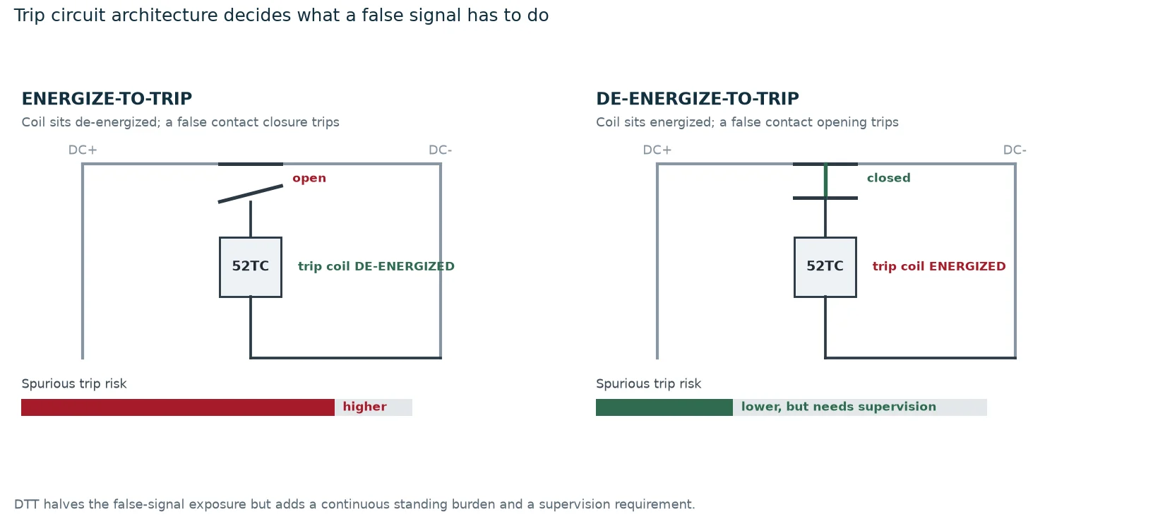
Most of the mitigations above are maintenance actions. Four are specification decisions, and they are worth raising at the enquiry stage rather than after the first event.
Trip circuit architecture. An energise-to-trip circuit leaves the trip coil de-energised in normal operation, so any false closure of a contact in the trip path operates the breaker. A de-energise-to-trip circuit holds the coil energised and requires a false opening to trip. The second has a lower spurious trip risk and a higher standing burden plus a continuous supervision requirement. The choice is a system-level reliability decision, not a preference.
Trip circuit supervision. Continuous supervision of the trip coil and its wiring turns an intermittent latent defect into a standing alarm. It does not prevent a spurious trip, but it catches the DC earth and the open coil before they matter. The methods and their blind spots are covered in this guide to trip circuit supervision.
Auxiliary contact complement and quality. Specify the number of changeover contacts, and specify that the block is mechanically linked to the breaker position rather than driven from a separate relay. A 126 kV transmission bay such as the LW36-126 with 40 kA breaking capacity typically carries a larger auxiliary complement than a distribution breaker, and the scheme usually needs all of it.
Mechanism accessibility for latch measurement. Latch engagement is a wear dimension that has to be measured. A mechanism that requires partial dismantling to reach the measurement will not be measured, and an unmeasured latch is a latch that fails without warning. On compact distribution units such as the LW8-40.5 at 0.5 MPa rated gas pressure, confirm at the enquiry stage what access the maintenance programme will actually have.
None of these choices removes the need for the routine work. Linkage condition, auxiliary contact overlap, DC insulation and mechanism latch dimensions all degrade between overhauls, and the inspection content that catches them is set out in this guide to SF6 circuit breaker maintenance.
A breaker that trips without a fault is a message about the trip circuit or the mechanism, not about the protection. Prove which by reading the event record first. If the relay did not operate, look for a second DC earth before looking anywhere else, because the two-point earth mechanism accounts for the largest share of these events and it is the one that can be confirmed in ten minutes with a voltmeter. If the breaker opened with no control power at all, stop looking at circuits and start measuring the latch.
If you are specifying a bay and want the trip circuit architecture, the auxiliary contact complement and the anti-pumping scheme reviewed against your protection philosophy, the SF6 circuit breaker technical library collects the related material, and you can send the control schematic for a review before the enquiry is issued.
The most common cause is a second earth fault on an unearthed DC control system, which completes a path through the trip coil. Other causes include induced transients on unshielded control cable, chattering auxiliary contacts, a failed anti-pumping circuit, and mechanical self-release from a worn latch or low spring charge.
Read the relay event record. A real trip shows a pickup, a trip decision and a timestamp consistent with the breaker’s open indication. A spurious trip shows the breaker opening with no relay pickup at all, or with a pickup that never reached a trip threshold.
Because the DC system is unearthed, so a single connection to earth completes no circuit and no current flows. The risk appears when a second earth occurs on the opposite pole, which can then complete a path through a trip coil or short out a control element.
Pumping is repeated close-open cycling caused by a close command that stays applied while the breaker keeps tripping. Each cycle applies a full interruption duty to the interrupter and a full charge to the mechanism, which erodes contacts and can damage the mechanism within a few operations. Anti-pumping logic exists to permit exactly one close per command.
Yes. Vibration can momentarily make a trip path through an auxiliary contact with the wrong overlap or a loose contact block, and it can cause an electromechanical auxiliary relay to chatter if the excitation approaches the armature’s natural frequency. Both events are too brief for a relay to record, which is why they are often missed.
At commissioning, after any change to the control circuit, and at every major overhaul. The test takes minutes: hold the close command, trip the breaker, and confirm it stays open for at least five seconds before releasing and reapplying the command.