Offshore Wind 66 kV Collection Systems: Breaker Selection for Salt Spray and Vibration
How 66 kV changed the collection system, what C5-M salt spray demands in measurable terms, and why the breaker boundary runs along the shoreline.
Read More
A circuit breaker interlock is not an accessory added at the end of a design. It is the set of physical and electrical constraints that make the correct switching sequence the only sequence available. In a high voltage bay, three devices must act in a fixed order: the circuit breaker, the disconnector, and the earthing switch. Each has a job the others cannot do. The breaker interrupts current. The disconnector opens a visible gap and carries no current while it moves. The earthing switch ties an isolated section to earth so a technician can stand next to it. Reverse the order and the result is not an alarm on a screen — it is an arc inside a compartment someone may be standing beside.
This guide covers what the interlock chain actually has to guarantee, the five preventions that most utilities and high voltage SF6 circuit breaker specifications are built around, how mechanical, key and electromagnetic interlocks are constructed, the accident chain that runs when one link is missing, and how to prove the whole chain works before a panel is energised.
The sequence is not a convention. It follows directly from what each device is rated to do.
A circuit breaker is the only device in the bay designed to interrupt load current and fault current. Its interrupter, its operating mechanism and its arcing contacts are all sized for that duty, and IEC 62271-100 defines how it is type tested for it.
A disconnector is a different animal. It is a isolating device with a visible break, and it has no rated breaking capacity for load current. Opening one under load draws an arc that the contacts were never designed to extinguish, which is why the disconnector operating mechanism is mechanically blocked while the breaker is closed. IEC 62271-102 governs disconnectors and earthing switches, and it also sets the interlocking expectations for the pair.
An earthing switch is the safety device. It connects an isolated section to the station earth so that residual capacitive charge is drained and the section is held at earth potential while people work. Some earthing switches carry a rated short-circuit making capacity so they can be closed onto a circuit that is still live by mistake; many do not. Where the switch has no making capacity, closing it on an energised conductor is a direct three-phase fault applied by hand.
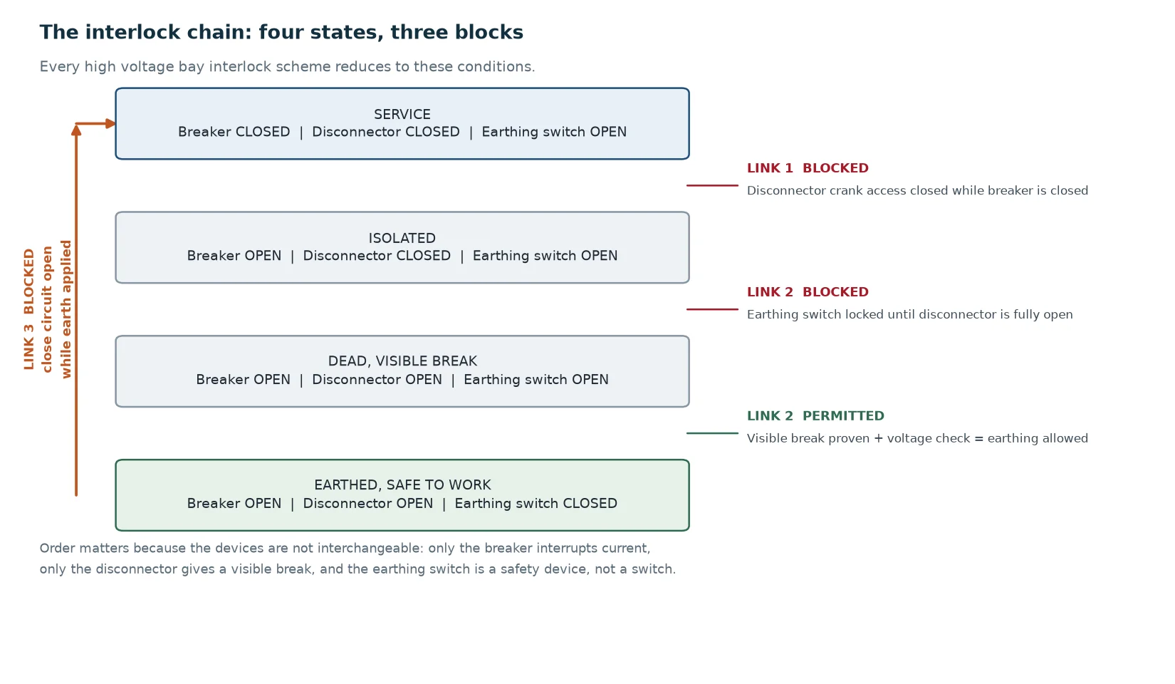
Those three capability statements produce the whole logic. The breaker must be open before the disconnector moves. The disconnector must be open before the earthing switch closes. The earthing switch must be open before anything is re-energised.
Almost every interlock scheme in service, from a 12 kV ring main unit to a 252 kV live tank installation, reduces to three conditional links. Everything else is implementation.
This is the load-breaking prevention. The blocking element is usually a mechanical slide or cam that physically prevents the disconnector crank from being inserted, combined with an electrical cut-off of the disconnector motor supply taken from the breaker’s closed auxiliary contact. Both are needed: the mechanical block protects the operator at the panel, and the electrical block protects against a remote command.
This is the live-earthing prevention, and it is the one with the highest consequence if it fails. The interlock must prove two things before the earthing switch can close: that the disconnector is fully open, and — on designs that include it — that the voltage presence indication on the cable or line side shows dead. The mechanical version links the earthing switch operating shaft to the disconnector position. The electrical version puts the disconnector’s open auxiliary contact and the voltage relay contact in series with the earthing switch motor circuit.
This is the reverse direction, and it is the link most often found defeated after maintenance. A rising shutter on the breaker truck track, or an auxiliary contact in series with the closing coil, must prevent the circuit from being energised into an earth. It matters because the dangerous case is not the operator who deliberately earths a live circuit — it is the crew that finishes work, forgets one earthing switch, and closes the breaker from the control room.
Chinese and many Asian utilities formalise the requirement as the five preventions. The naming varies by project, but the engineering content is stable. The table below maps each prevention to the device that enforces it and the specific failure it removes.
| Prevention | What it blocks | Typical enforcing mechanism |
|---|---|---|
| No load-breaking at the disconnector | Opening or closing a disconnector while it carries current | Mechanical shutter over the crank insertion point tied to breaker position; motor supply cut by breaker auxiliary contact |
| No closing with the truck out of position | Closing the breaker with the withdrawable truck between test and service position | Position switch in series with the close circuit; mechanical block on the close latch |
| No racking under load | Withdrawing or inserting the truck while the breaker is closed | Racking interlock keyed to the breaker open state, plus a shutter over the racking access |
| No earthing of a live circuit | Closing the earthing switch onto an energised conductor | Cam or key interlock from the disconnector open position; voltage presence relay contact in series |
| No energising into an earth | Closing the breaker or disconnector while an earthing switch is closed | Rising shutter on the truck track; earthing switch auxiliary contact in series with the close coil |
There is a sixth item that belongs in the same table even though it is often listed separately: no entry into a live compartment. On metal-clad and GIS designs the cable compartment door bolt is released only in the earthed position, so the door cannot open on a live bar. That is an interlock in the strict sense — it is enforced by hardware, not by a warning label.
Mechanical interlocks use cams, levers, shutters and bolts. They need no power supply, no software and no settings, which is why they are the most trusted layer. A positive mechanical interlock on an earthing switch cannot be bypassed without disassembling the mechanism, and the linkage is type tested — a figure of 2,000 operations is typical for the interlock function itself, separate from the main contact endurance.
Two mechanical details are worth understanding because they explain most field behaviour. The first is the interrogation slide on metal-clad panels: a sliding plate that can only expose one operating access at a time, so the disconnector crank and the earthing switch crank cannot both be inserted. The second is the three-position mechanism used on many disconnectors, with fixed positions for closed, open, and earthed. The mechanism makes the transition from closed to earthed a two-step operation with the intermediate open position as a distinct mechanical state. That intermediate state is what gives the operator a visible dead condition before earthing.
Trapped key systems use a key that is held captive in one lock and can only be released when the associated device reaches a defined state. The classic sequence for a feeder is: open the breaker, which releases the disconnector key; use that key to operate the disconnector, which releases the earthing switch key; use that key to close the earthing switch, which releases the compartment door key. The logic is physical, visible and independent of the DC supply.
This is why key interlocks are still preferred for transformer and busbar sections, and why the failure mode is specific: a duplicate key. A spare key cut to bypass a trapped key chain defeats the entire sequence silently, and nothing on the panel records that it happened.
Electromagnetic interlocks are relay and contact logic built from auxiliary contacts, position switches and voltage relays. They are fast to integrate, easy to retrofit, and the only practical way to enforce interlocking across bays — a bus coupler breaker that must block a feeder disconnector two panels away cannot be handled by a mechanical cam.
They also carry a dependency that mechanical hardware does not: correct DC supply, correct settings and correct wiring. A position switch that is adjusted to release two millimetres early will pass a static check and fail the moment the mechanism settles. And because the logic lives in the control circuit, it can be defeated by a link, a lifted wire, or a maintenance mode selector left in the enabled position.
| Type | Depends on | Strength | Characteristic failure |
|---|---|---|---|
| Mechanical | Linkage geometry only | Cannot be defeated without disassembly | Seized or corroded linkage; cam removed during a repair and not refitted |
| Key (trapped key) | Physical custody of the key | Visible, supply-independent, cross-bay capable | Duplicate or spare key; key removed in an unsafe position |
| Electromagnetic | DC supply, settings, wiring | Cross-bay logic, remote blocking, easy retrofit | Misadjusted position switch; maintenance mode left enabled; lifted wire |
| Procedural | Training and supervision | Covers what hardware cannot reach | Degrades under time pressure; leaves no physical evidence |
A good design does not choose one. Mechanical blocking handles the direct danger at the device, key interlocks handle sequences across a section, electromagnetic logic handles remote and automatic operations, and procedure covers the rest. When one layer is missing, the remaining layers are asked to do work they were not designed for.
It is worth walking through what actually happens, because the sequence explains why interlock testing deserves more attention than it usually gets.
The energy released is worth quantifying, because “arc flash” as a phrase has lost its meaning. Take a 40 kA fault at 72.5 kV, cleared in five cycles at 50 Hz — 100 ms. With an arc voltage of roughly 1 kV across the fault path, the dissipated energy is about 40 kA × 1 kV × 0.1 s, or 4 MJ. That is roughly the chemical energy in a kilogram of TNT, released inside a compartment in a tenth of a second. Change the clearing time to 60 ms and the energy falls to 2.4 MJ; the scaling is linear in time, which is why protection speed and interlock integrity are two halves of the same problem.
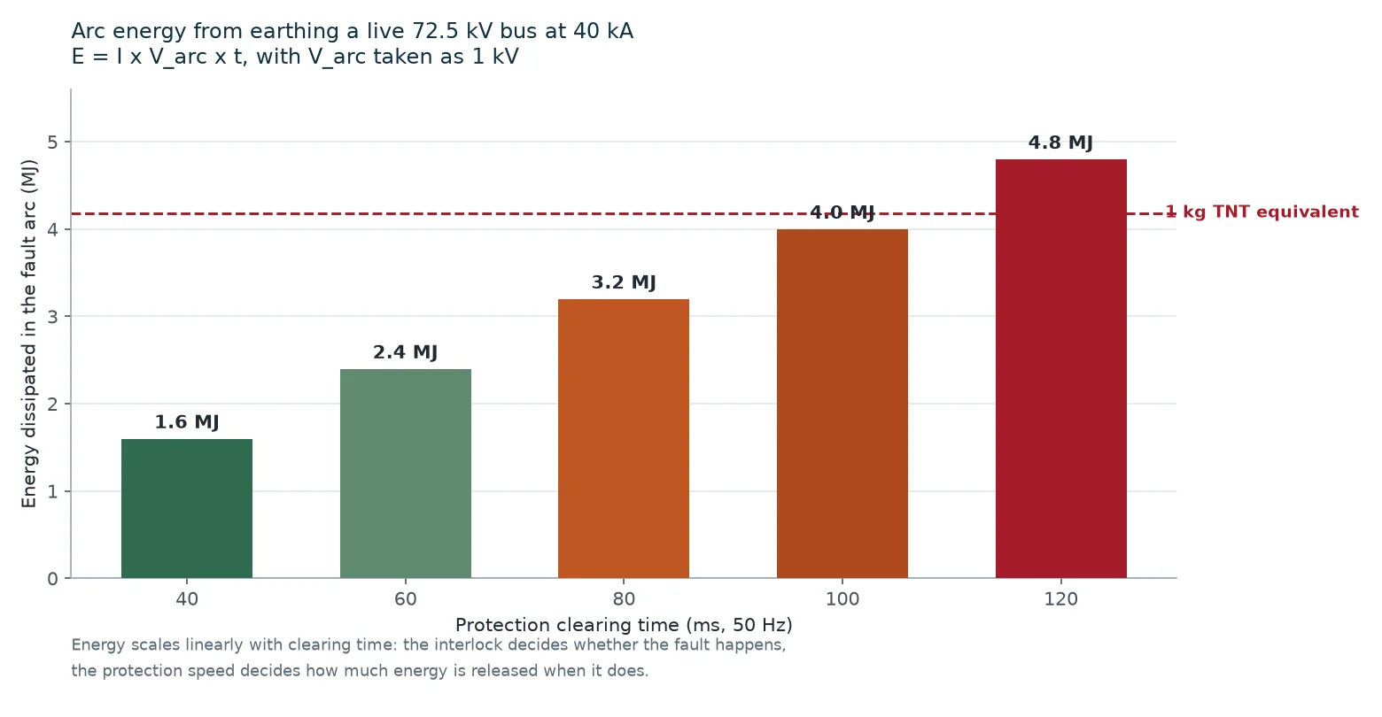
Two conclusions follow. First, the earthing switch itself becomes part of the fault path, and a unit without short-circuit making capacity may be destroyed and may fail to contain the arc. Second, the indicator lamp on the panel is not evidence of isolation. It is evidence that a lamp circuit is healthy. Isolation is proven by a visible break plus a voltage check, which is exactly why the interlock chain forces the sequence rather than relying on the operator’s confidence.
Most interlock failures are not design failures. They are maintenance and human failures, and they have recognisable signatures.
Every one of these is visible during a routine inspection. None of them is visible in an electrical test.
Interlocks are proven cold, with the panel isolated. The purpose is twofold: to demonstrate that every forbidden action really is refused, and to demonstrate that every permitted action is not accidentally blocked. The second half is the one that gets skipped, and it is the half that produces the workaround culture where interlocks get forced later.
| Step | Action | Pass criterion |
|---|---|---|
| 1 | Breaker closed, attempt to insert the disconnector crank | Access physically blocked; crank cannot be inserted |
| 2 | Breaker closed, attempt disconnector operation from remote | Motor supply dead; no movement |
| 3 | Disconnector closed, attempt to close the earthing switch | Earthing switch refuses; mechanism stops at the block |
| 4 | Earthing switch closed, attempt to close the breaker | Close circuit open; no close, no reclose attempt |
| 5 | Earthing switch closed, attempt to open the compartment door | Door bolt remains locked |
| 6 | Remove DC control supply, repeat steps 3 to 4 | Mechanical blocks still refuse; electrical blocks fail safe or are proven to fail open on the correct side |
| 7 | Run the full permitted sequence end to end without force | Every allowed action completes with normal effort |
| 8 | Check key cannot be removed in an unsafe position | Key trapped until the device reaches the defined state |
Step 6 is the one that reveals design intent. An electrical interlock that loses its block when the DC supply is removed is a fail-dangerous design, and the commissioning record should say so explicitly rather than leaving it to be discovered later. The same discipline applies when the bay is commissioned as part of a wider substation; the sequence and protection interactions are covered in more depth in this guide to SF6 circuit breakers in substations.
Interlocking is usually described in the switchgear specification and then assumed to be somebody else’s scope. Four items are worth writing into the breaker enquiry so the interface is unambiguous.
First, state which interlocks are supplied with the breaker and which belong to the panel or the protection scheme. The breaker normally provides the position auxiliary contacts and the mechanism-side blocks; the panel provides the shutters, the interrogation slide and the door interlock. Ambiguity here is the most common source of a missing link.
Second, specify the auxiliary contact complement. Two changeover contacts per pole position are a common minimum, but schemes that use separate close and trip supervision, plus SCADA indication, plus a local interlock chain, routinely need more. A compact 40.5 kV unit such as the LW8-40.5 at 0.5 MPa rated gas pressure has a different auxiliary budget from a transmission-class breaker, and the enquiry should reflect the actual scheme.
Third, state whether the earthing switch must carry short-circuit making capacity. If the design intent is that earthing is only ever applied to a proven-dead circuit, a switch without making capacity is acceptable — but only if the interlock and the voltage check are both specified. If a fault-making earthing switch is required, say so, because it changes the contact and mechanism design.
Fourth, define the gas density interlock behaviour. Loss of SF6 density must block operation rather than trip the breaker; the alarm and lockout stages belong in the interlock logic, and the pressure thresholds should be stated. The behaviour of the density relay itself is covered in this article on the SF6 gas density monitor.
For transmission-class bays where the interlock chain spans several panels and the layout is project-specific, the customisation conversation usually starts with the bus configuration rather than the breaker. A 252 kV installation such as the LW-252 customised outdoor breaker is typically specified alongside a one-and-a-half breaker or double busbar arrangement, where the interlocks must handle bus coupler logic and transfer sequences. The 126 kV class sits in the same territory: the LW36-126 with 40 kA breaking capacity is often installed in bays where disconnector, earthing switch and breaker interlocks are split across two panels.
Finally, ask for the interlock functional test record with the equipment. Not the type test certificate for the mechanism — the functional record for the actual panel, with the device position and date against each blocked action. That document is what turns a design intention into a verified installation, and it belongs in the same file as the dielectric and contact resistance results described in this guide to SF6 circuit breaker testing.
Interlock logic is a chain of three conditional links, and the chain is only as strong as its weakest layer. Mechanical blocking should be treated as the primary defence because it cannot be defeated by a lifted wire. Key interlocks should be treated as the cross-section layer because they are visible and supply-independent. Electromagnetic logic should be treated as the layer that extends reach, with the explicit understanding that it depends on DC supply, settings and wiring. Procedure should be treated as the layer that covers everything the hardware cannot see, and never as a substitute for a missing block.
If you are specifying a bay and want the interlock chain, the auxiliary contact complement and the earthing switch duty reviewed against your single line diagram, the SF6 circuit breaker technical library collects the related material, and you can send the arrangement for a sequence check before the enquiry is issued. The maintenance side of the same subject — how linkages, cams and position switches degrade between overhauls — is covered in this guide to SF6 circuit breaker maintenance.
A circuit breaker interlock is a mechanical, key-based or electrical constraint that prevents the breaker, the disconnector and the earthing switch from being operated out of sequence. It exists so that the disconnector cannot open under load, the earthing switch cannot close on a live circuit, and the circuit cannot be energised while an earth is applied.
IEC 62271-102 sets the requirements for disconnectors and earthing switches and expects interlocking between them and the associated breaker. IEC 62271-200 covers metal-enclosed switchgear and defines the interlock provisions for that family. The precise list for a given panel is normally fixed by the project specification, which should be treated as the governing document.
Yes, and some maintenance tasks require it. The correct approach is a documented maintenance mode: local control only, remote commands blocked, physical earthing and isolation confirmed, and the bypass state recorded and reset before the panel returns to service. What must not happen is an undocumented bypass — a bar on a stiff lever, a lifted wire, or a spare key.
Mechanical, because it depends on linkage geometry rather than on a power supply or a setting. Key interlocks are close behind and have the advantage of being visible across a section. Electromagnetic interlocks are the most flexible and the most dependent on maintenance discipline.
Only if the design allows for the possibility of closing it on a live circuit, or if the earthing switch is used to make fault current deliberately — for example on some line-earthing arrangements. Where earthing is only ever applied to a circuit proven dead by a visible break and a voltage check, a switch without making capacity is acceptable, provided the interlock and the voltage check are both in place.
At commissioning, after any maintenance that disturbed a linkage or a control circuit, and at every major overhaul. Interlock checks belong in the routine inspection, not only in the commissioning programme, because the failures that matter — a missing cam, paint, corrosion, a misadjusted switch — develop between overhauls.