Offshore Wind 66 kV Collection Systems: Breaker Selection for Salt Spray and Vibration
How 66 kV changed the collection system, what C5-M salt spray demands in measurable terms, and why the breaker boundary runs along the shoreline.
Read More
Every extra-high-voltage line that runs lightly loaded at night needs somewhere to dump its charging power, and in most grids that job belongs to a shunt reactor bank. Switching that bank is one of the least understood duties an SF6 circuit breaker faces, and a shunt reactor switching circuit breaker is judged by physics that no fault test ever exercises. The current is tiny compared with a short circuit, but the breaker chops it before its natural zero, stores energy in the reactor’s magnetic field, and hands that energy back as a voltage spike. Done badly, the result is reignition, voltage escalation, and damaged inter-turn insulation. This guide walks through the chopping mechanism, shows how a few amperes become a 1.5 p.u. overvoltage, explains what IEC 62271-110 testing actually proves, and sets out what to check before you commit a breaker to reactor duty.
A shunt reactor absorbs reactive power to hold voltage down on long lines and cable networks. Its current is set by the bank rating, not by any fault condition. A 150 MVAr bank on a 400 kV system draws roughly 216 A per phase, and smaller 72.5 kV or 126 kV banks draw proportionally less. The breaker never sees kiloamperes here. What makes the duty hard is the opposite of the fault case: the current is so small that the arc becomes unstable long before the natural current zero, and the breaker interrupts it prematurely.
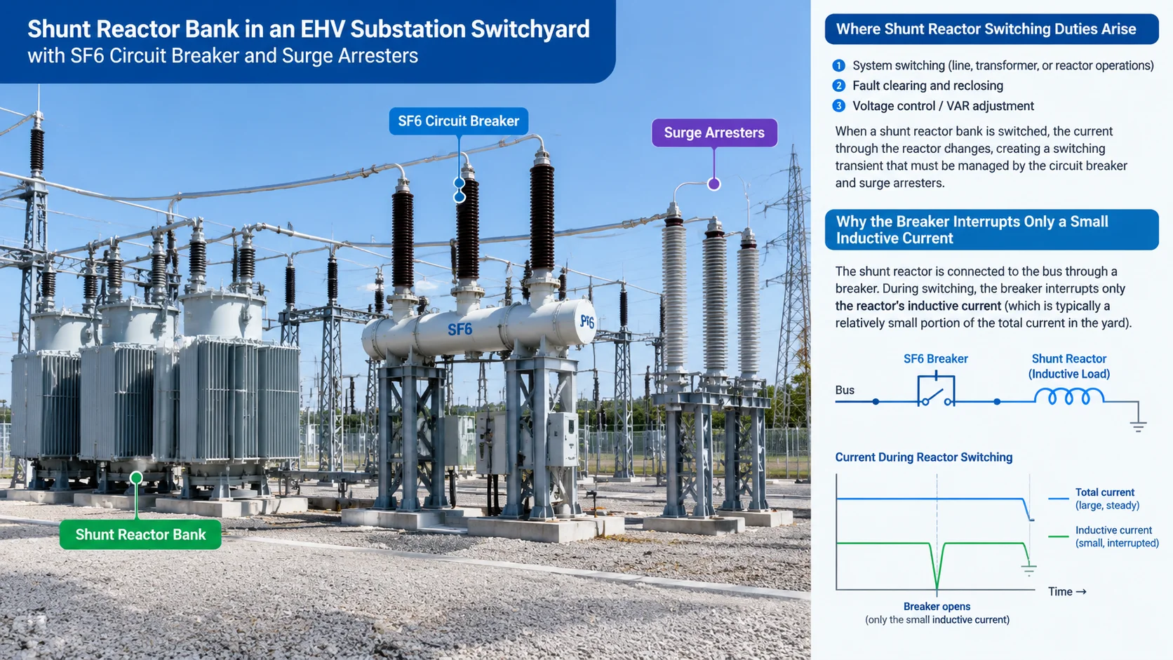
Three things separate this duty from everything else in the switching catalogue. The current is inductive and small, so the energy stored in the reactor’s magnetic field at the instant of interruption has nowhere to go except into the stray capacitance around the bank. The circuit is oscillatory: reactor inductance against a few nanofarads of bushing and bus capacitance rings at kilohertz rates. And the recovery voltage builds slowly while the gap must hold immediately, unlike a fault interruption where the source side is clamped by the short circuit itself.
IEC 62271-110 treats shunt reactor switching as a distinct category of inductive load switching, with its own test duties, because none of the conclusions drawn from short-circuit or capacitive tests carry over. If your specification lists a reactor bank among the switched elements, the breaker behind it needs to be evaluated for this duty explicitly. The same applies on industrial networks: plants that use reactor compensation, and 126 kV industrial grids where a breaker such as the LW36-126 outdoor SF6 circuit breaker may be scheduled against both fault clearing and reactive power equipment.
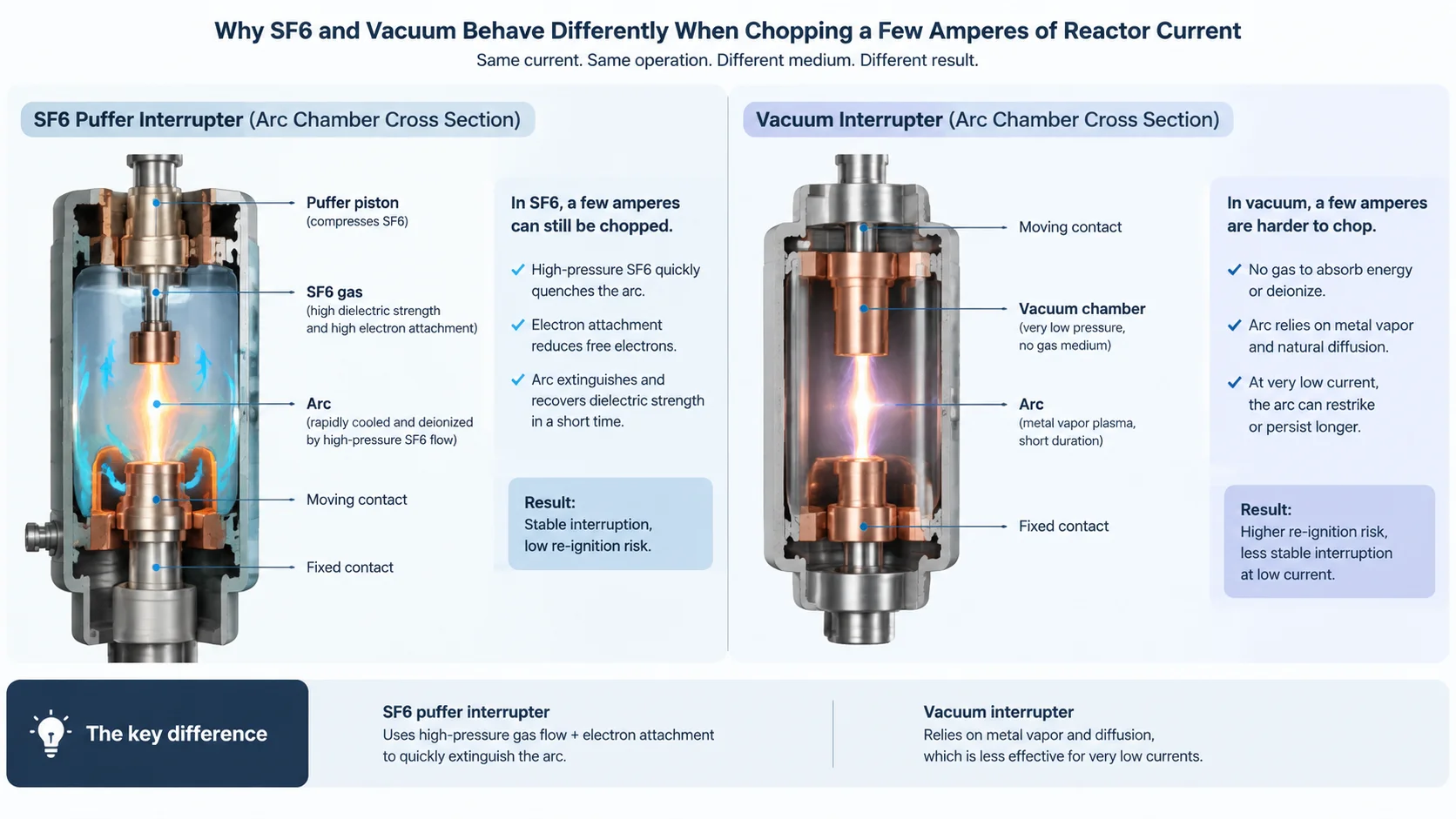
An SF6 puffer arc is a gas-dynamic phenomenon. At high current, the arc column is thick, hot and conductive, and the puffer pressure builds against it. As the current approaches zero, the column contracts, the energy input falls, and the arc becomes unstable. Below a critical current the arc can no longer sustain itself between separating contacts, and it extinguishes abruptly. The current at that instant is called the chopping current, and for modern SF6 puffer interrupters it is typically in the range of 3 to 5 A.
Where does the 3 to 5 A figure physically come from? It is not a setting; it is the point where the energy balance of the arc column tips. Near current zero, the arc survives on the thermal inertia of the gas flow and the residual ionisation between contacts. The nozzle diameter, the puffer pressure at separation, the contact material and the SF6 pressure all shift this balance. An aggressively quenched design chops at the higher end because it strips energy out of the column faster; a softer design chops lower but takes longer to build dielectric strength. This is a genuine trade-off in interrupter design, and it is why two breakers with the same rating can behave very differently on a reactor bank.
Vacuum interrupters chop for a different reason. Their arc is a metal-vapour plasma, and interruption happens at a natural current zero when the vapour dissipates. The chopping current depends strongly on the contact material, from about 4 A for well-designed copper-chromium contacts to well over 10 A for older alloys. Vacuum also brings a second phenomenon SF6 does not have: virtual chopping, where high-frequency oscillations in the external circuit interact with the arc and force the current to zero prematurely. Both effects raise the energy trapped in the reactor at the instant of interruption.
The energy trapped in the reactor at the chopping instant is ½·L·ich². When the arc extinguishes, this energy transfers into the total capacitance to earth on the reactor side, Ct, which includes the reactor windings, its bushings, any connecting buswork and the breaker’s own grading capacitance. The voltage that appears is:
ΔV = ich × √(L / Ct)
The square-root term is the surge impedance of the reactor circuit, and it is enormous: a few henries against a few nanofarads gives tens of kilo-ohms. That is why amperes of chopping current produce hundreds of kilovolts of jump.
| Parameter | Value | How it is derived |
|---|---|---|
| Bank rating | 150 MVAr, 400 kV, three-phase | Given |
| Phase voltage (rms / peak) | 231 kV / 327 kV | 400 / √3; peak = rms × √2 |
| Reactor current per phase | 216 A | 50 MVAr ÷ 231 kV |
| Inductance per phase, L | 3.4 H | Vphase ÷ (ω × I) = 231 kV ÷ (314 × 216 A) |
| Total capacitance to earth, Ct | 4 nF | Windings + bushings + buswork (typical range 2–8 nF) |
| Surge impedance √(L/Ct) | 29 kΩ | √(3.4 H ÷ 4 nF) |
| Chopping current, ich (SF6 puffer) | 4 A | Typical 3–5 A range |
| Voltage jump ΔV | ≈ 117 kV | 4 A × 29 kΩ |
| Reactor-side peak (worst case) | ≈ 1.36 p.u. | 1 + 117 / 327 |
The worst case occurs when chopping happens at the crest of the reactor current, which is the instant the supply voltage passes through zero, because the current lags the voltage by 90 degrees. The source side then swings toward its full peak while the reactor side is elevated by ΔV, so the gap sees the sum. The sensitivity table below shows why two breaker designs, or two layouts of the same bank, can produce very different results.
| Chopping current | Ct = 2 nF (compact layout) | Ct = 4 nF (typical) | Ct = 8 nF (cable-connected) |
|---|---|---|---|
| 3 A (good SF6 puffer) | 1.38 p.u. | 1.27 p.u. | 1.19 p.u. |
| 4 A (typical SF6 puffer) | 1.51 p.u. | 1.36 p.u. | 1.26 p.u. |
| 5 A (high-pressure SF6 puffer) | 1.63 p.u. | 1.45 p.u. | 1.32 p.u. |
| 10 A (vacuum, unfavourable contact alloy) | 2.26 p.u. | 1.89 p.u. | 1.63 p.u. |
Three practical conclusions fall straight out of this table. First, more capacitance on the reactor side is your friend; a short cable stub between breaker and bank can halve the overvoltage. Second, the chopping current matters linearly, so interrupter selection is not a formality. Third, the numbers that land near 1.5 p.u. are exactly the numbers a well-designed SF6 puffer produces on a typical layout, which is why that figure dominates the conversation about reactor switching.
Chopping is only the first act. After the arc extinguishes, the voltage across the breaker gap is the difference between the decaying oscillation on the reactor side and the power-frequency recovery on the source side. The gap must recover dielectric strength faster than this voltage rises. If it does not, the gap breaks down again, and the reactor is re-energised through a high-frequency loop: the source charges the stray capacitance, the capacitance discharges back through the gap, and the process can repeat several times within a few milliseconds.
Each reignition adds energy to the reactor-side circuit, and the oscillation amplitude can escalate step by step. The frequencies involved are in the hundreds of kilohertz, so the voltage is not distributed evenly across the reactor winding. The first turns from the line end absorb a disproportionate share, and inter-turn insulation that comfortably withstands power-frequency and lightning impulse stress can fail under a steep-fronted reignition transient. This is the classic failure mode of reactor banks switched without mitigation, and it is why utilities care about reignition counting, not just peak voltage.
SF6 and vacuum behave differently in this race. An SF6 gap recovers most of its dielectric strength within the first fraction of a millisecond after current zero, because the high-pressure gas deionises quickly and electron attachment removes free carriers. Reignitions in an SF6 interrupter are usually single events that do not escalate. A vacuum interrupter recovers quickly too, but at very low currents the metal-vapour plasma can persist, and restrikes in vacuum tend to be multiple and steep-fronted. The comparison is developed further in our article on SF6 versus vacuum circuit breakers, and it is one reason vacuum remains dominant indoors at medium voltage while SF6 takes reactor duty at transmission voltages.
The 1.5 per-unit value that appears in so many reactor specifications is worth unpacking, because it is often misread as a clause of IEC 62271-110. It is not. The standard defines how the duty shall be tested: the test duties, the circuit parameters, the neutral arrangements and the measurements to be recorded. The overvoltage limit itself comes from the insulation coordination of the reactor. A shunt reactor’s inter-turn insulation is designed against power-frequency, lightning and switching impulse stress with defined margins, and the switching overvoltage the winding can tolerate typically lands between 1.5 and 2.0 p.u. depending on design and age. Utilities therefore write 1.5 p.u. or 2.0 p.u. into their specifications as a procurement criterion, and the breaker is expected to meet it, with or without external mitigation.
Two details of the standard matter when you read a test report. The first is the neutral arrangement. A reactor bank with an earthed neutral lets the first pole to clear see phase voltage recovery; an isolated neutral forces the neutral point to shift when the first phase clears, raising the recovery voltage on that pole by a factor of up to 1.5. An ungrounded bank is therefore the harder test case, and a breaker qualified only on a grounded arrangement is not automatically qualified for the other. The second is the capacitance range. The test circuit’s Ct must span the range of real installations, because the sensitivity table above shows how strongly the result depends on it. If your layout puts unusually little capacitance on the reactor side, ask how the type test covered that corner.
The test philosophy is to reproduce the energy exchange, not just the current. A direct test circuit connects the breaker to a source transformer and a real reactor bank, with a capacitor bank representing the total capacitance to earth of the field installation. Voltage dividers on both sides of the breaker record the reactor-side and source-side transients simultaneously, because the interesting quantity is their difference across the gap.
A properly documented reactor switching test report should let you extract:
Synthetic testing becomes necessary at extra-high voltage, where no laboratory source can supply a full 252 kV reactor bank at realistic power. The synthetic method supplies the interrupting current from one circuit and the recovery voltage from another, with IEC 62271-110 constraining how the two are synchronised so the gap experiences a faithful transient. For buyers, the practical takeaway is to ask for the test report early in a reactor-connected project. Our overview of SF6 circuit breaker testing explains how type, routine and commissioning tests fit together.
Very few reactor installations rely on the breaker alone. The mitigation toolkit has four members, and they solve different parts of the problem.
| Mitigation | What it does | What it does not do | Typical use |
|---|---|---|---|
| Metal-oxide surge arrester at the reactor terminal | Clamps the phase-to-earth peak to the arrester protection level | Does nothing about reignitions or the steepness of the front | Nearly always present; baseline protection |
| RC snubber across the breaker or at the reactor | Damps the oscillation, slows dv/dt, protects inter-turn insulation | Adds components to maintain; sizing needs the actual L and Ct | Ungrounded banks, vacuum breakers, retrofit on problematic installations |
| Controlled (point-on-wave) opening | Times contact separation so the gap is strong exactly at a natural current zero, avoiding chopping altogether | Requires a breaker with low operating-time scatter and per-pole control | Transformer and reactor banks where nuisance inrush or reignitions already cost money |
| Interrupter selection (SF6 puffer over vacuum at HV) | Low chopping current and fast, non-escalating recovery | Not a substitute for insulation coordination | Transmission voltage reactor duty |
Controlled opening deserves a note of its own, because it turns the problem around. Instead of accepting whatever instant the mechanism happens to separate the contacts, a point-on-wave relay commands each pole so that the gap has full dielectric strength at the natural current zero. The arc then extinguishes without chopping, the trapped energy is zero, and the whole cascade of chopping, reignition and escalation never starts. The technique, its hardware requirements and its economics are covered in our article on controlled switching.
For a reactor-connected project, the selection question is not only the fault ratings on the nameplate. The duties that decide long-term reliability are the small ones: the 200 A of reactor current, the frequent operations, the restrike behaviour after years of service. When we configure a breaker for reactor duty we look at four things in order.
First, the interrupter’s chopping behaviour and recovery characteristic, which for transmission voltages favours the SF6 puffer designs used across our range. A unit like the LW-252 outdoor SF6 circuit breaker with 1050 kV lightning impulse withstand carries the 252 kV reactor and line duties in one frame, and its multi-break arrangement with grading capacitors distributes the transient recovery voltage evenly across the interrupters, a point that matters when the recovery voltage is set by an ungrounded reactor bank.
Second, the neutral arrangement of the bank, because it decides whether the first-pole-to-clear factor is 1.0 or 1.5, and therefore what recovery voltage the gap must hold. Third, the capacitance on the reactor side of the breaker, which you should extract from the substation layout before the sensitivity is calculated rather than after. Fourth, the endurance class of the breaker against frequent operations: a reactor bank that switches daily accumulates operations at a rate fault duty never approaches, which is where the classification codes in our article on M1/M2, E1/E2 and C1/C2 endurance classes become a purchasing decision rather than fine print. On industrial 126 kV networks where reactor compensation and grid protection share the same line-up, the LW36-126 industrial grid protection breaker covers both roles with a single qualified design.
Finally, put the duty in context with its siblings. Reactor switching is the inductive twin of the capacitive current switching duty, where the roles of L and C are exchanged and the risk shifts from chopping to restrike. A line-end breaker that faces both a shunt reactor and a long cable sees both families of transients, and the short-line fault duty adds its own terminal-bounded TRV on top. A specification that lists all three explicitly is a specification a manufacturer can quote against accurately.
It is the premature interruption of the reactor current before its natural zero, caused by arc instability at low current. An SF6 puffer typically chops at 3 to 5 A. The energy trapped in the reactor inductance at that instant converts into a voltage spike across the stray capacitance of the bank.
Because the reactor circuit’s surge impedance √(L/Ct) is extremely high, on the order of tens of kilo-ohms. Multiplying amperes by kilo-ohms yields hundreds of kilovolts. In the worked example above, 4 A across a 29 kΩ surge impedance adds roughly 117 kV, or 0.36 p.u., to the peak phase-to-earth voltage.
No. The standard defines the test duties and measurement requirements for inductive load switching. The 1.5 p.u. value is an insulation-coordination criterion for the reactor that utilities embed in their purchase specifications. Your breaker and mitigation scheme must meet the limit your reactor requires.
Yes. When the first pole clears an ungrounded bank, the neutral point shifts and the recovery voltage across that pole rises by up to a factor of 1.5 compared with an earthed arrangement. IEC 62271-110 treats the two cases as distinct test duties.
SF6 puffer interrupters combine a low chopping current with fast, single-event recovery that rarely escalates. Vacuum interrupters are excellent at medium voltage, but at very low currents their chopping behaviour is contact-material dependent and restrikes can be multiple and steep-fronted, which stresses inter-turn insulation most of all.
When the calculated chopping overvoltage exceeds the reactor’s withstand, when the bank is ungrounded, or when the layout puts little capacitance on the reactor side. Arresters clamp the peak, RC snubbers damp the oscillation, and controlled opening eliminates chopping at the source. Most transmission installations combine at least two of these.
Reactor switching rewards the buyer who reads test reports closely and matches the interrupter to the duty rather than to the fault number alone. If you are specifying breakers for a reactor-connected substation, the full range and application notes are collected in our SF6 circuit breaker knowledge base, and our engineers will review your bank parameters, neutral arrangement and layout capacitance against the relevant test duties before quotation.