Offshore Wind 66 kV Collection Systems: Breaker Selection for Salt Spray and Vibration
How 66 kV changed the collection system, what C5-M salt spray demands in measurable terms, and why the breaker boundary runs along the shoreline.
Read More
Most switching transients are not caused by a breaker that is too small. They are caused by a breaker that operated at the wrong instant. Close a transformer at the wrong point on the voltage wave and the core saturates, the inrush current reaches eight to twelve times rated current, and the differential protection may trip the bank you just energised. Close a capacitor bank at the voltage crest and the inrush peaks at tens of kiloamperes. Open a shunt reactor away from its natural current zero and the arc chops, the voltage spikes, and the winding pays for it. Controlled switching — also called point-on-wave or synchronised switching — replaces “whatever instant the mechanism happens to choose” with a commanded instant, and it delivers results that would otherwise require a physically larger breaker, heavier arresters or expensive filters. This guide explains where the technique wins, what the control targets actually are, what it demands from the breaker hardware, and how to judge whether it pays for itself.
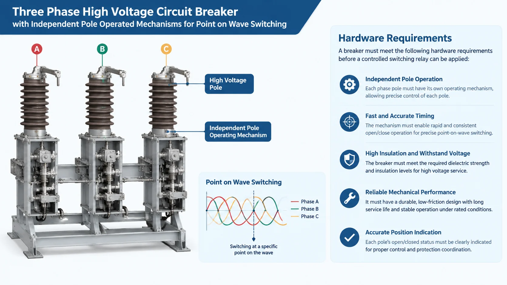
A conventional breaker closes or opens when its coil is energised, plus or minus the mechanical scatter of the mechanism. A controlled switching circuit breaker adds a controller between the station control and the pole operating coils. The controller knows the breaker’s operating time under current conditions, knows the target phase angle for the duty in hand, and issues the command early enough that the contacts meet — or separate — exactly at that angle.
Three quantities decide whether the concept works. The first is operating-time consistency: a mechanism whose close time wanders by several milliseconds cannot be commanded to a target defined in electrical degrees, because at 50 Hz one millisecond is 18 degrees. The second is drift compensation: operating time changes with ambient temperature, control voltage, and the time the mechanism has sat idle, so the controller must model these and correct. The third is adaptive learning: modern controlled switching relays measure the actual operating time after every operation, feed it back, and update their prediction, so the system converges on the installed breaker rather than the nameplate one.
The precision that matters is scatter, not average time. A breaker whose close time is always 42.0 ms is easy to command; one that averages 42 ms but swings between 39 and 45 ms is useless for point-on-wave duty, because ±1.5 ms of scatter is ±27 degrees of phase uncertainty. This is why the mechanical health of the breaker is a precondition, and why the consistency of spring, hydraulic and pneumatic drives described in our article on SF6 circuit breaker operating mechanisms directly determines whether controlled switching can be applied.
The correct closing instant differs by load, and getting this wrong is the root of most inrush problems. The unifying principle is simple: pick the instant where the steady-state condition at closing matches the physical state of the load, so the transient has nothing to build on.
| Application | Closing target | Why | Transient avoided |
|---|---|---|---|
| Power transformer energisation | Voltage peak, adjusted for residual flux | Steady-state flux is zero at voltage peak, so no DC flux offset builds in the core | Inrush current of 8–12× rated, harmonic distortion, differential protection trips |
| Capacitor bank energisation | Voltage zero across the breaker | Zero volts across the gap means no prestrike arc and no step voltage on the bank | Back-to-back inrush at tens of kA, fuse and capacitor damage |
| Shunt reactor energisation | Voltage peak | Reactor current starts at zero, matching steady state, so the oscillation is minimal | Energisation transient and core saturation of the reactor |
| Transmission line energisation | Voltage peak, per pole, against trapped charge | Maximises margin between source voltage and line trapped voltage | Switching overvoltage at the line end, arrester stress |
Worth deriving once, because it explains the transformer row of the table. In steady state the core flux lags the voltage by 90 degrees: φ(t) = −Φmax·cos(ωt). If you close at the voltage zero crossing, the steady-state flux at that instant is −Φmax, but the physical core flux cannot jump, so a DC component of Φmax is injected. The core then swings between zero and 2·Φmax for many cycles. Since the saturation knee sits at roughly 1.2 to 1.3·Φmax, the core spends part of every cycle saturated, and the magnetising current is limited only by the air-core inductance of the primary — hence the enormous inrush spikes. Close at the voltage peak instead and the steady-state flux is zero at t=0, no offset is injected, and the transformer simply starts as if it had been running forever.
| Closing instant | Steady-state flux at closing | DC flux offset | Peak flux reached | Expected inrush |
|---|---|---|---|---|
| Voltage zero (t=0 of the sine) | −Φmax | +Φmax | ≈2.0·Φmax | Severe, core saturates |
| Voltage peak | 0 | 0 | ≈1.0·Φmax | Negligible |
| Voltage peak with +0.6·Φmax residual flux, uncompensated | 0 | +0.6·Φmax | ≈1.6·Φmax | Moderate |
| Residual-flux compensated target | ≈+0.6·Φmax (matched) | ≈0 | ≈1.0·Φmax | Negligible |
The last two rows are the practical subtlety. A transformer that was de-energised on one half-cycle retains residual flux, and if the next energisation ignores it, the perfect voltage-peak instant is no longer perfect. Advanced controlled switching schemes measure or estimate the residual flux per phase and shift each pole’s closing target so the steady-state flux starts exactly where the residual left off. This is why per-pole operation is not optional for transformer duty: the three phases need three different instants.
On the opening side, the targets are about letting the arc extinguish on its own terms.
For shunt reactors, controlled opening times each pole so that contact separation plus arcing time lands the extinction exactly at a natural current zero. The arc then never becomes unstable at low current, no chopping occurs, and the entire chopping-overvoltage and reignition cascade described in our shunt reactor switching guide is avoided at the source. This is the cleanest reactor mitigation available — no arresters to maintain, no snubbers to size — provided the breaker’s scatter is genuinely small.
For capacitor banks, the goal is to open at a clean current zero and let the gap recover before the recovery voltage crests. Capacitive switching is a restrike problem as much as an overvoltage problem, and the C1 and C2 classes defined in our capacitive current switching guide quantify how a breaker is tested for it. Controlled opening reduces the probability of restrike by removing the premature-separation cases where the gap is still weak when the recovery voltage builds. For transformer magnetising current — a few amperes at most — the same logic applies as for reactors: extinguish at a natural zero rather than chopping the core flux mid-cycle.
Controlled switching is a joint design between the relay and the breaker. When we prepare a breaker for point-on-wave duty, the checklist looks like this:
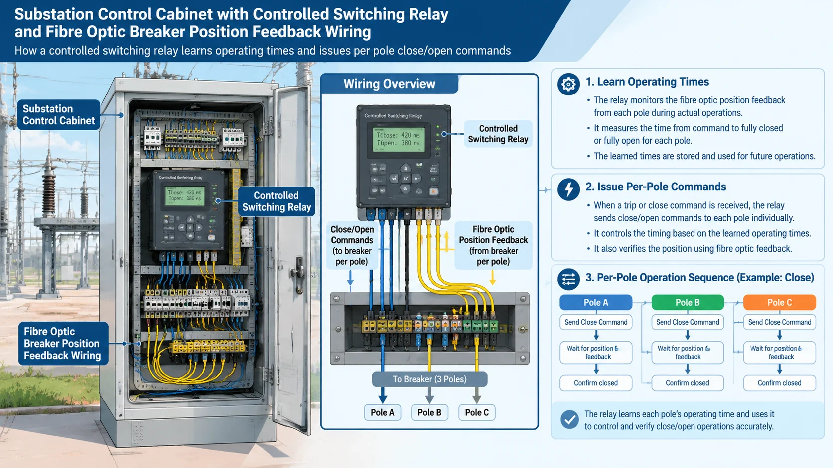
The operating sequence is worth following once. In steady state the relay holds a learned operating-time model per pole, corrected for measured temperature and control voltage. When the station issues an energisation command for a transformer, the relay computes the voltage-peak targets for the coming cycle, adjusts them for estimated residual flux, subtracts the predicted operating time from each target instant, and staggers three per-pole commands. After the operation, the measured contact timings come back through position feedback and the model is updated. If a pole missed its window by more than the tolerance, the relay flags it — and a growing miss is one of the earliest mechanical warnings a breaker can give, visible in the timing records that a travel curve analysis would confirm.
The investment case rests on avoided events, so it has to be built from your own network’s history. The worksheet below uses clearly labelled illustrative figures — replace every number with your own before treating the conclusion as real.
| Item | Illustrative figure | Basis |
|---|---|---|
| Controlled switching relay, per breaker | USD 15,000 | Relay plus wiring and commissioning |
| Independent-pole preparation, per breaker | USD 8,000 | Incremental cost versus ganged operation |
| Transformer energisation events avoided per year | 12 severe inrush events | Daily switching of two banks |
| Cost per avoided event (inspection, accelerated ageing, nuisance trip risk) | USD 4,000 | Site-specific — use your outage and maintenance data |
| Capacitor bank inrush damage avoided per year | USD 6,000 | Fuse operations, capacitor element loss |
| Breaker contact wear reduction on frequent duties | USD 3,000 / year | Deferred arcing-contact replacement, fewer overhauls |
| Annual avoided cost | USD 57,000 | 12 × 4,000 + 6,000 + 3,000 |
| Simple payback | ≈ 5 months | 23,000 ÷ 57,000 |
Even if your site’s real numbers come out a quarter as favourable, the payback on a frequently switched bank is measured in a couple of years, not a decade. The cases where controlled switching does not pay are equally clear: a bank switched twice a year, a breaker with worn mechanics whose scatter no relay can fix, and networks where the transients were never a documented problem in the first place.
If controlled switching is on your specification, four questions separate a genuine point-on-wave offering from a marketing line. What is the guaranteed operating-time scatter, and at which temperatures and control voltages was it measured? Is independent pole operation standard for the rating in question, or an option with lead-time implications? Can the relay’s learned model be exported and reviewed, so your commissioning engineer can see the convergence rather than trust it? And what is the documented fallback behaviour when the relay removes itself from service? A manufacturer who answers these from test records is quoting a system; one who answers in adjectives is quoting a feature list.
Our range supports this end to end. For transmission duties, the LW-252 customized outdoor SF6 circuit breaker can be configured for point-on-wave operation with independent pole mechanisms and the control interfaces the relay expects, which is often the deciding factor on transformer and reactor banks where inrush and switching overvoltage are documented problems. On industrial 50/52 Hz networks, the LW36-126 outdoor SF6 circuit breaker for 52 Hz power distribution brings the same per-pole consistency to 126 kV industrial grids, where capacitor banks for power-factor correction are the most common controlled-switching candidate. Both draw on the same interrupter platform documented across our LW series model comparison.
It is the technique of commanding each pole of a breaker to close or open at a chosen phase angle of the voltage or current waveform, instead of at whatever instant the mechanism happens to reach. A controlled switching relay predicts the breaker’s operating time and issues the command early so the contacts meet the target within a tolerance of a few milliseconds.
Because the steady-state core flux is zero at the voltage peak, so no DC flux offset is injected into the core. Closing at a voltage zero injects a full Φmax offset, driving the core to about twice nominal flux and deep into saturation, which produces the classic 8–12× inrush current.
Residual flux is the magnetisation left in a transformer core by the half-cycle at which it was last de-energised. Advanced controlled switching schemes estimate it per phase and shift each pole’s closing target so the steady-state flux continues from where the residual left off, keeping the peak at about one per unit.
When the breaker’s scatter is small enough to land extinction exactly at a natural current zero, yes — the arc never becomes unstable at low current and no chopping energy is trapped. This makes controlled opening one of the most effective mitigations for reactor switching overvoltage.
At 50 Hz, one millisecond equals 18 degrees, so practical schemes require per-pole operating-time scatter on the order of one millisecond or better, across the site’s temperature and control-voltage range. A mechanism with wandering timings cannot be commanded to a target, whatever the relay’s algorithm does.
Usually not. The economics come from avoided events, so the value scales with switching frequency. A bank switched a few times a year rarely accumulates enough avoided cost to justify the relay; a capacitor bank or transformer switched daily can pay for the system within months.
Timing is the cheapest transient mitigation that never appears on a single-line diagram. If you are weighing a controlled switching scheme against a larger breaker, more arresters or bigger filters, send us your switching frequency, bank ratings and event history — the SF6 circuit breaker knowledge base covers the underlying duties, and our engineers will tell you honestly whether point-on-wave pays on your numbers.