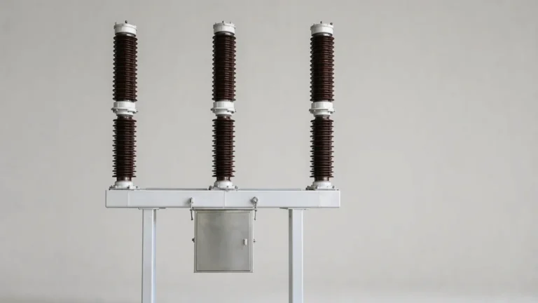
LW36-126 Explained: 3150 A, 40 kA and 40 kA/3 s in Practical Terms
What the LW36-126 model number covers, what it does not, and how to pick between the six variants and specify the items the model omits.
Read More
Ask a supplier for the breaking capacity of an SF6 breaker and you will be told 40 kA. Ask what happens when that 40 kA is interrupted with a fault 2 km down the line rather than at the terminals, and the conversation usually stops. Yet that is the case that decides whether a short line fault circuit breaker survives its first real fault — and it is a case where the recovery voltage rises several times faster than in the terminal-fault test the rating plate refers to.
This article explains the short-line fault duty from first principles: why the line side produces a sawtooth rather than a smooth recovery voltage, how to calculate the rate of rise, why the 90% duty rather than the 100% duty is the onerous one, and what to ask for in a type test report before accepting a breaker for line protection. It applies to outdoor breakers across the SF6 circuit breaker range used on overhead transmission and sub-transmission lines.
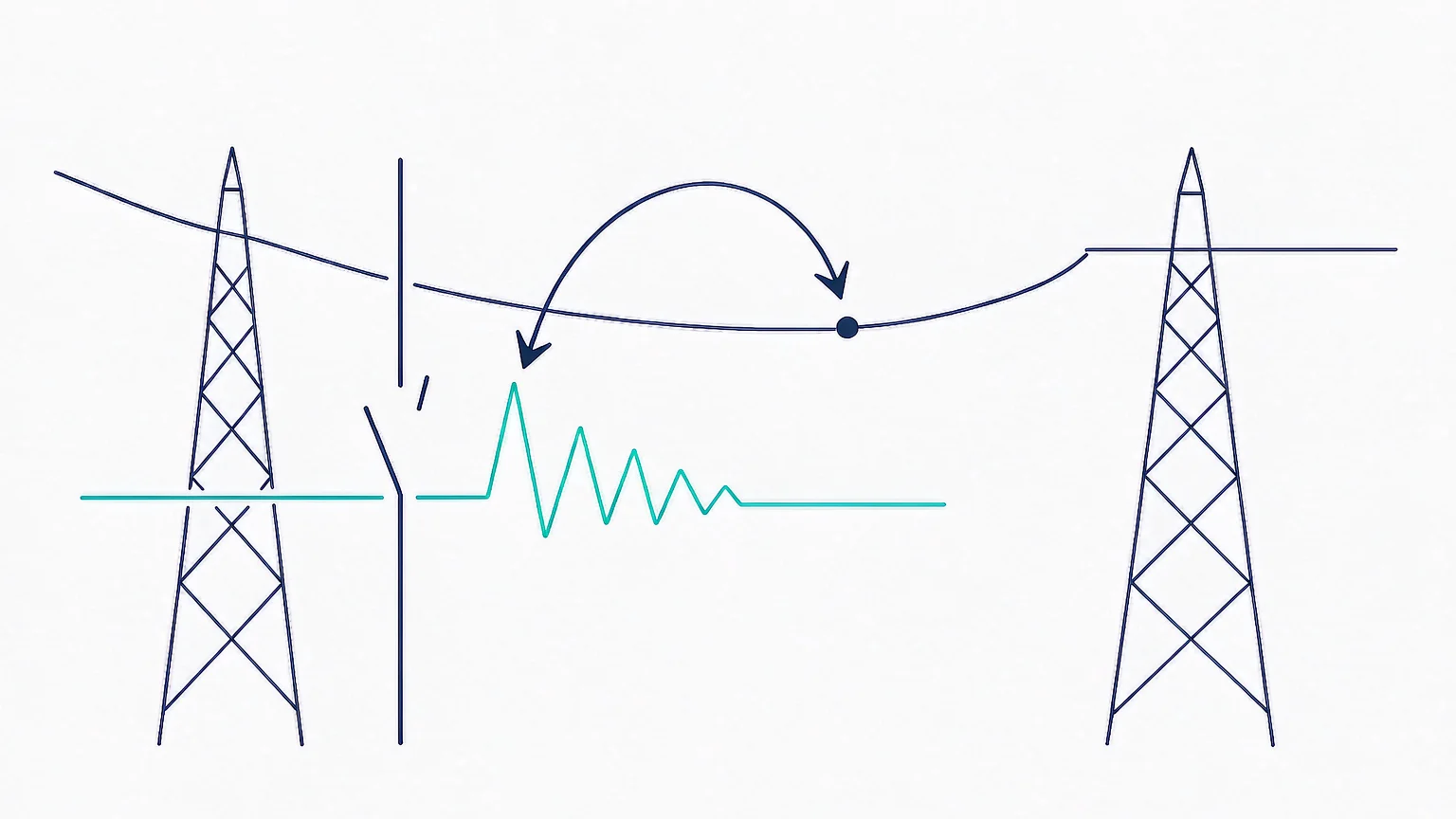
A terminal fault sits directly at the breaker bushings. A short-line fault — the older term is kilometric fault — sits a short distance down the line: typically a few hundred metres to a few kilometres. The distance is small enough that the fault current is barely reduced by the line impedance, but large enough that the line between the breaker and the fault behaves as a distributed network rather than as a lumped element.
That combination is what makes it hard. You get almost the full fault current, plus a transmission line behaving like a transmission line. Either condition alone is manageable. Together they are the worst recovery-voltage duty a line breaker sees in normal service.
The physical picture is simple enough: a lightning strike, a tree, a broken conductor, or insulation flashover at a tower a couple of kilometres out. The protection sees a fault, the breaker opens, and the line between the breaker and the fault is still charged and still full of travelling waves.
In a terminal fault, the only thing the breaker has to recover against is the source. After current zero, the source-side voltage returns in a smooth 1-cosh or exponential shape at power frequency, and the rate of rise is set by the source inductance and the capacitance of the substation. For a 126 kV system at 40 kA, that is typically a few hundred volts per microsecond.
In a short-line fault, the breaker has to recover against two things at once. The source side still does its smooth power-frequency recovery. The line side does something entirely different, because the line is a distributed energy store with a characteristic surge impedance.
During the fault, current flows from the breaker into the line and out at the fault point. At the moment of interruption, the line side is not at zero volts — it holds whatever voltage the fault current produced across the line impedance between the breaker and the fault. That trapped state cannot decay instantly. It has to propagate.
The mechanism is a travelling wave. The breaker terminal injects a wave into the line, the wave travels to the fault point at close to the speed of light, reflects off the low-impedance fault with a reflection coefficient near −1, and returns. At the terminal, the returning wave subtracts from the outgoing one, producing a sharp corner. The next reflection starts the cycle again.
The result is a sawtooth waveform superimposed on the source-side recovery. The slope of the rising edge is the line-side rate of rise, and the period of the sawtooth is the round-trip travel time:
t = 2L / v, where L is the distance to the fault and v is the propagation velocity, roughly 300 m per microsecond for an overhead line.
A fault 2 km away gives a round-trip time of about 13 µs. A fault 5 km away gives about 33 µs. Those are the timescales the interrupter has to work with, and they are two orders of magnitude shorter than a power-frequency half cycle.
The line-side rate of rise of recovery voltage is the single most useful number in this whole subject, because it is the one the interrupter actually has to beat. For a short-line fault it is:
S = √2 · ω · Z · IL
where ω is 2πf, Z is the surge impedance of the line, and IL is the line-side fault current. The surge impedance is the property that governs everything: roughly 450 Ω for an overhead line, and 30 to 60 Ω for a cable.
Put numbers in. At 50 Hz, 450 Ω and 40 kA:
S = 1.414 × 314 × 450 × 40,000 = 8.0 × 10⁹ V/s
That is 8 kV per microsecond. Compare it with the terminal-fault recovery on the same breaker, which is usually below 1 kV per µs. The line side is an order of magnitude faster. No amount of source-side damping changes it, because the source side is not where the wave is coming from.
| Case | Surge impedance | Fault current | Line-side RRRV | Round-trip time at 2 km |
|---|---|---|---|---|
| Overhead line, 126 kV | 450 Ω | 40 kA | 8.0 kV/µs | 13 µs |
| Overhead line, 252 kV | 450 Ω | 50 kA | 10.0 kV/µs | 13 µs |
| Overhead line, 72.5 kV | 450 Ω | 31.5 kA | 6.3 kV/µs | 13 µs |
| Cable, 126 kV | 45 Ω | 40 kA | 0.8 kV/µs | 13 µs |
The cable row explains why cable circuits are usually specified as terminal-fault duties and why a cable fault does not stress the interrupter the way an overhead line fault does. The surge impedance is ten times lower, so the rate of rise is ten times lower, even though the current is the same.
This is the counter-intuitive part, and it is the reason the standard tests at 90% rather than at rated current.
Two quantities move in opposite directions as the fault point walks away from the breaker. The further out the fault, the lower the current, because more line impedance is in series. But the further out the fault, the longer the line, and the longer the line the higher the line-side recovery voltage can build before the reflected wave returns to interrupt it.
At zero distance you have a terminal fault: full current, no line-side recovery at all. At 90% of rated breaking current you have almost full current and a line long enough to develop a substantial sawtooth. The product of the two — which is what the interrupter experiences — peaks somewhere before the current has fallen far, and the standard puts that peak at the 90% duty.
By the time you are down to 75% of rated current, the rate of rise has fallen by a quarter and the duty is measurably easier. Hence the two standard duties, L90 and L75, with L90 as the governing case.
The sawtooth does not rise forever. It is bounded by the source-side voltage, because once the line-side recovery reaches the source-side recovery the two waveforms merge. In practice the line-side peak lands in the range of 1.6 to 1.9 times the peak phase-to-earth voltage, which for a 126 kV system is around 170 to 200 kV. The interrupter therefore has to withstand a fast rising wave to that level within roughly 13 to 35 µs of current zero.
IEC 62271-100 treats short-line faults as a separate series of test duties, not as a variation on the terminal-fault duties. The standard fixes the line surge impedance used in the test circuit and defines the L90 and L75 duties by the fraction of rated short-circuit breaking current they are run at, with a line model that reproduces the round-trip travel time.
Three practical points follow from how the test is built.
This is also where the standards themselves diverge in emphasis. IEC 62271-100 sets out the L-series duties explicitly; IEEE C37.09 handles the equivalent case through its own test procedure and circuit descriptions. A breaker certified only to one scheme should not be assumed to have demonstrated the other. The IEC 62271-100 and IEEE C37 comparison sets out where the two schemes line up and where they do not.
This is the single most expensive misunderstanding in breaker procurement. A breaker that passes the terminal-fault duty at 100% of rated breaking current has demonstrated that it can interrupt that current against a power-frequency recovery voltage. It has said nothing about its ability to interrupt 90% of that current against a recovery voltage rising ten times faster.
The interrupter’s margin is consumed by two different mechanisms. In a terminal fault, the limiting factor is usually thermal: the gas between the contacts is hot and conductive at current zero, and the post-arc current has to be suppressed before the recovery voltage drives it back into an arc. In a short-line fault, the thermal recovery problem is still there, but it is now compressed into a much shorter window — a few microseconds instead of tens — because the recovery voltage arrives almost immediately.
An interrupter with generous thermal margin will pass both. An interrupter designed tightly to the terminal-fault duty will pass T100 and fail L90. The failure mode is a re-ignition within the first 20 to 50 µs after current zero, visible on the test oscillogram as a sharp collapse of the recovery voltage and a resumption of current.
| Parameter | Terminal fault (T100) | Short-line fault (L90) |
|---|---|---|
| Fault current | 100% of rated | 90% of rated |
| Recovery voltage shape | 1-cosh / exponential | Sawtooth on source-side recovery |
| Typical RRRV | 0.3 – 1.0 kV/µs | 6 – 10 kV/µs |
| Critical window after current zero | tens of µs to ms | first 10 – 50 µs |
| Dominant limiting mechanism | Thermal re-ignition | Thermal re-ignition under fast RRRV |
| Evidence in a typical report | Usually present | Often missing |
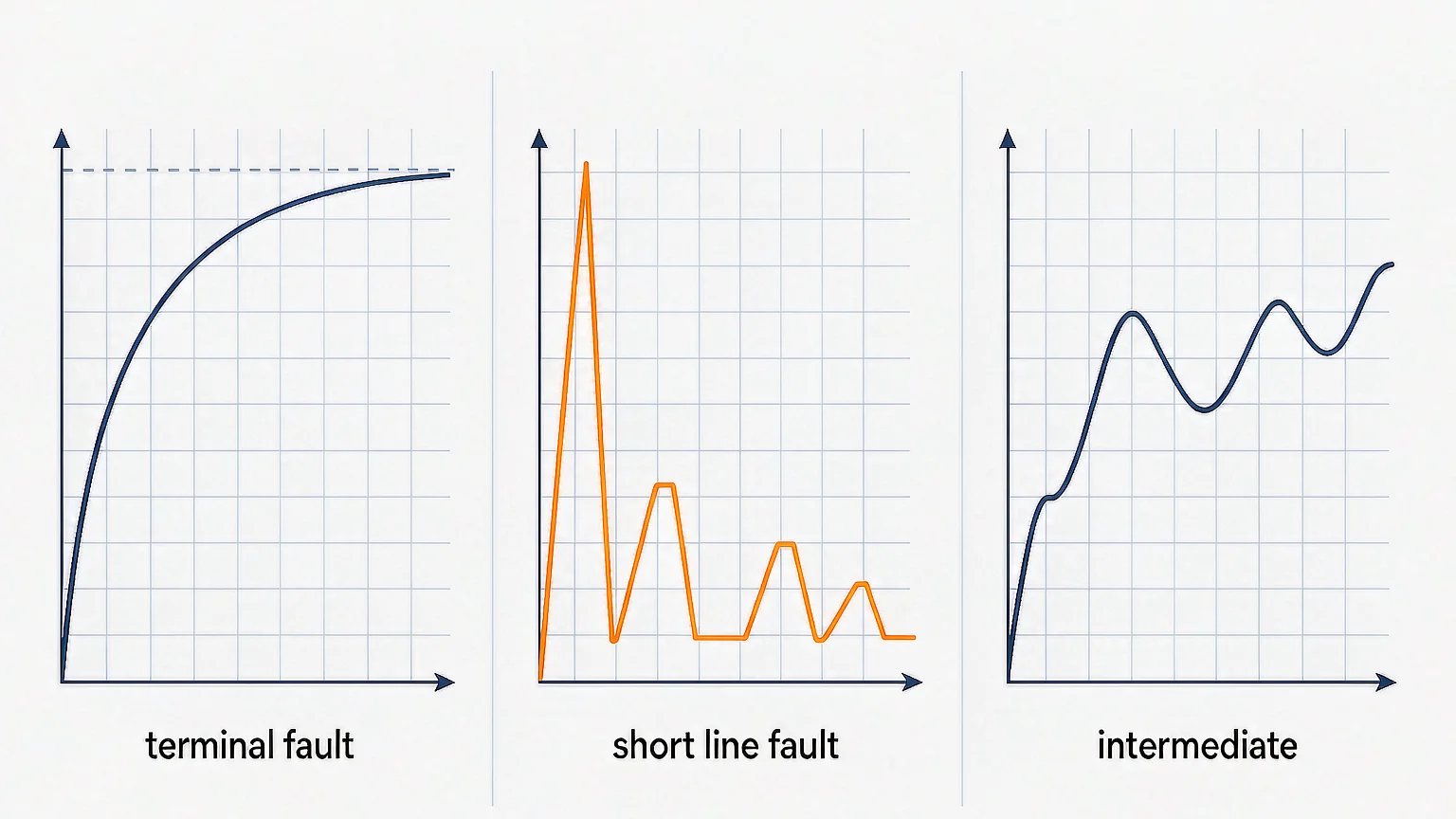
Two common cases reduce or remove the short-line duty, and it is worth knowing which one you are in before paying for extra test evidence.
Cable circuits. Surge impedance is 30 to 60 Ω, so the line-side rate of rise falls to well under 1 kV/µs even at 40 kA. Most utilities treat cable faults as terminal faults for specification purposes. The exception is a long cable with an overhead section at the far end, where the overhead surge impedance dominates the reflection.
GIS with very short connections. If the breaker is directly connected to a transformer or to a busbar with no significant line length, there is no line to produce the sawtooth. The relevant duty becomes the transformer-limited or reactor-limited fault instead, which has its own severity. The breaker type and configuration determines which case applies.
Where the breaker sits at the end of an overhead line — which is the normal arrangement in sub-transmission and rural distribution networks — the short-line duty applies in full and should be specified.
Ask for the oscillograms, not the certificate summary. Four things to check:
The SF6 circuit breaker testing guide covers the rest of the test programme and how the type test, routine test and commissioning test fit together. For the specific numbers, the type test report is the only document that counts.
Six items worth writing into a purchase specification when the breaker protects an overhead line.
For a 126 kV line position, a breaker such as the LW36-126 with 40 kA breaking capacity is the class of equipment where this duty is routine rather than exotic: 40 kA at 126 kV on an overhead line is exactly the combination that produces an 8 kV/µs sawtooth. At the top of the range, the 252 kV 50 kA split-type breaker faces 10 kV/µs, and at 72.5 kV the LW9-72.5 4000 A unit sits in the same regime at a lower current.
The short-line fault is the duty that separates a breaker designed for line protection from one designed to pass a catalogue test. The physics is not complicated — a travelling wave on a line with a known surge impedance, reflecting off a fault a couple of kilometres out — and the resulting rate of rise is easy to calculate. What is easy to overlook is that the governing case is 90% of rated current rather than 100%, and that the terminal-fault evidence on the certificate does not cover it.
Specify L90 and L75, ask for the oscillograms, and check that the recovery voltage has a sawtooth on it. For the capacitive counterpart of this duty — where the problem is trapped charge rather than a travelling wave — see capacitive current switching. The wider SF6 circuit breaker article library covers the rest of the equipment.
A fault a short distance down the line from the breaker, typically a few hundred metres to a few kilometres. The current is nearly the full fault level, but the line between the breaker and the fault behaves as a distributed network and produces a fast sawtooth recovery voltage on the line side.
Because the rate of rise of recovery voltage, not the current, is the limiting factor. At 90% of rated current the line is long enough to build a sawtooth while the current is still almost at rated value, giving a rate of rise around 8 to 10 kV/µs against well under 1 kV/µs for a terminal fault.
S = √2 · ω · Z · IL, with ω = 2πf, Z the line surge impedance (about 450 Ω for an overhead line) and IL the line-side fault current. At 50 Hz, 450 Ω and 40 kA that gives 8 kV/µs.
Usually not. Cable surge impedance is 30 to 60 Ω, so the line-side rate of rise is roughly ten times lower than for an overhead line at the same current. Most specifications treat cable faults as terminal faults unless a long overhead section is involved.
A re-ignition within the first 20 to 50 µs after current zero: the recovery voltage collapses sharply and current resumes. It is easy to miss if you only look at the summary sheet rather than the trace.
Yes. The L-series test voltage is set using the first-pole-to-clear factor, which is 1.3 for effectively earthed systems and 1.5 where the neutral is isolated. Check which one the report was produced at before comparing it with your network.