Lightning Impulse, Power Frequency and Chopped Wave Tests: Reading 1050 kV BIL Correctly
Published: Author: Lisa
Lightning impulse withstand voltage is the rating that decides whether a 245 kV breaker can be used on a particular line, and it is also the rating most often misread. A datasheet line reading 1050 kV means that a wave of that peak was applied to the insulation for 1.2 microseconds of front and 50 microseconds to half value, and that nothing flashed over. It does not mean the site will ever produce 1050 kV. It does not mean the same unit will hold 1050 kV at 2,000 metres of altitude, and it says nothing at all about the morning the SF6 pressure is low and the ambient is minus thirty. Reading the number correctly means separating what was tested, where it was tested, and what the site will actually do to it.
This article takes the 1050 kV level that goes with a 245 kV system — the rating carried by the 252 kV breaker rated at 1050 kV impulse — and works through the three dielectric tests behind it, the numbers a buyer should expect to see in the report, and the four corrections that turn a laboratory figure into a site figure. If you are comparing high-voltage SF6 circuit breakers from two or three suppliers, the tables below are the ones worth carrying into the technical meeting.
What the number on the datasheet is measuring
Rated lightning impulse withstand voltage is defined in IEC 60071-1 as a standard level, and applied in IEC 62271-1 as a type test. Two things about it are worth fixing in your mind before anything else. First, it is a peak value in kilovolts, not an rms value, and not a rate of rise. Second, it is a withstand level, not a breakdown level. The test asks a yes-or-no question: did the insulation survive fifteen applications of this wave without flashover. There is no “1050 kV at which it fails at 1,080” in the report, because the test is not run to find the failure point.
That distinction matters commercially. Two breakers can both be stamped 1050 kV and behave very differently in service, because one may have been designed with 12 percent margin on the air clearance and the other with 2 percent. The nameplate records the test that was passed, not the margin that was designed in. The only way to see margin is to look at the clearances, the creepage and the gas density in the same report.
The three dielectric tests, and the one that is not a test
High-voltage switchgear is qualified by three dielectric tests, and each one simulates a different event. Confusing them is the most common source of bad specification writing, because the three numbers move together in a catalogue but mean completely different things in a substation.
Test
Waveform
What it simulates
Where it stresses most
Lightning impulse (LI)
1.2/50 µs, peak kV
Direct or nearby lightning strike, travelling wave arriving along the line
External air clearance and the first turns of any winding; the bushing surface
Switching impulse (SI)
250/2500 µs, peak kV
Switching overvoltage, long-line energisation, fault clearing at high voltage
Long air gaps, phase-to-phase clearance, open contact gaps
Power frequency (PF)
50 or 60 Hz, rms kV, 1 minute
Continuous operating stress plus contamination, condensation and moisture ingress
Internal insulation, solid insulation, creepage paths under wet conditions
Chopped impulse
1.2 µs front, chopped at 2–6 µs
A strike that is interrupted by a flashover a few microseconds in
Inter-turn and layer insulation in windings, not breaker insulation
Note what the last row says. IEC 62271-1 does not include a chopped-wave dielectric test for switchgear. The chopped wave is a transformer duty, defined in IEC 60076-3, and it exists because a winding has turns at different potentials that a steep-fronted collapse can stress far beyond the terminal voltage. A breaker has no winding. When a breaker datasheet quotes a chopped-wave level, the useful questions are which standard it came from, whether it was type tested or calculated, and why the purchaser asked for it. In most cases the requirement has been copied from a transformer specification, and the supplier has answered with a number rather than a test. That is not fraud, but it is not evidence either.
The rest of this article therefore concentrates on the three tests that are real: impulse, switching impulse and power frequency. The wider sequence, including the mechanical and thermal duties that sit alongside them, is covered in the guide to SF6 circuit breaker type testing.
The 1.2/50 microsecond wave, defined precisely
The standard lightning impulse is a double-exponential wave with a virtual front time of 1.2 µs and a virtual time to half value of 50 µs. “Virtual” is the operative word: the actual wave has no sharp corner, so the front time is defined from two points on the recorded trace, at 30 percent and 90 percent of peak, with T1 equal to 1.67 times the interval between them. The tail is measured from the virtual origin to the point where the voltage has fallen to half of peak.
IEC 60060-1 allows T1 to deviate by 30 percent and T2 by 20 percent, which means a wave with a 0.9 µs front and a 45 µs tail is still a valid standard impulse. The measurement itself carries an uncertainty allowance of about 3 percent. Those tolerances are generous enough that a report quoting “1.2/50” without the measured values has told you nothing verifiable — the wave shape depends on the generator, the load capacitance of the test object and the connecting leads, and a 252 kV breaker column is a substantial load. Ask for the measured T1 and T2 on the oscillogram, not the nominal label.
The number of applications matters as much as the shape. The IEC practice for a withstand test is fifteen impulses of each polarity, with the insulation required to survive all of them. A report showing fewer applications, or one where flashovers are described as conditioning and the test continued, needs an explanation before it is accepted as evidence.
Why 245 kV equipment has three different impulse levels
There is no single impulse level for a given voltage class. IEC 60071-1 lists several, and the choice between them is an insulation coordination decision, not a manufacturing preference. The spread exists because exposure differs: a breaker at the end of a long overhead line with poor shielding sees more lightning than one inside a well-shielded substation two cable lengths from the transformer.
Um (kV)
PF withstand (kV rms)
LI withstand (kV peak)
SI withstand (kV peak)
Typical use
36
70
145 or 170
not standardised
MV distribution, industrial
72.5
140
325
not standardised
Sub-transmission, 66 kV networks
123
230
550
not standardised
110 kV transmission
145
275
650
not standardised
132 kV transmission
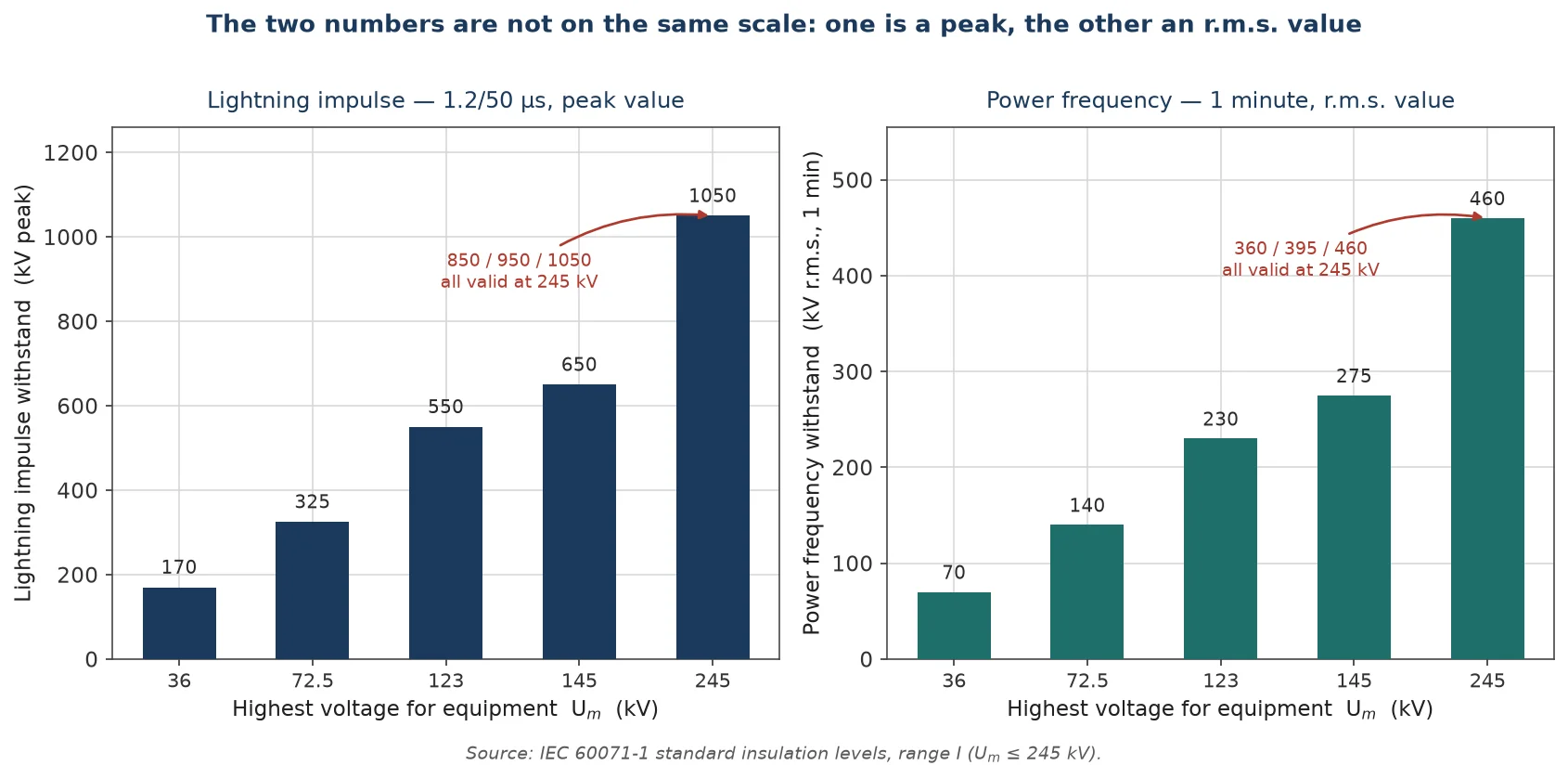
245
360, 395 or 460
850, 950 or 1050
750, 850 or 950
220 kV transmission, line entrance
Two features of that table are worth pointing out. The first is that the 245 kV row offers nine combinations, and the pairing between the power-frequency value and the impulse value is not free: a 1050 kV impulse level normally comes with the 460 kV power-frequency level, because both are sized for the same external clearance. If a quotation offers 1050 kV impulse with 360 kV power frequency, the two numbers have been assembled rather than designed, and the unit is probably a 850 kV design carrying a higher test stamp on paper.
The second is that switching impulse only becomes a standard requirement above 245 kV in the IEC range structure. Chinese practice, and most 252 kV equipment built for 220 kV systems, does quote a switching impulse level alongside the impulse and power-frequency values, typically 750 kV. If your insulation coordination study produces a switching impulse requirement, make sure it appears in the test report as a separate line rather than being assumed to be covered by the impulse test. At the other end of the range, a 72.5 kV breaker at 350 kV impulse is one step above the 325 kV table value, which is the normal way to buy margin where the study asks for it. The relationship between voltage class and equipment design is set out in more detail in the guide to SF6 breaker voltage classes.
One value is a peak and the other an r.m.s. figure; a quotation that pairs them from different tiers has been assembled, not designed.
What 460 kV of power frequency proves
The power-frequency test is often treated as the easy one, and that is a mistake. At 245 kV the standard level is 460 kV rms for one minute, the level carried by the 460 kV power-frequency unit in the same frame family. Phase-to-earth operating voltage at that class is 145.5 kV rms, so the test applies 3.16 times the service stress — continuously, for a full minute, with the insulation at its hottest and, for external insulation, with the surface wet in the wet test variant.
Three properties make this test the one that finds real manufacturing defects. It is applied for long enough that partial discharges have time to initiate and grow. It stresses the whole insulation system rather than just the air gap, so a void in cast resin or a contaminated gas zone shows up. And the wet variant stresses the external surface in a way an impulse never does, because a 1.2 µs front is over before surface leakage has time to develop. A unit that passes impulse cleanly and fails power frequency has a contamination, moisture or discharge problem, and it is the kind of problem that appears in service after two monsoon seasons rather than on the first lightning strike.
This is also where the pollution class and creepage decision meets the test report. The power-frequency withstand level is fixed by the standard; the creepage that makes it achievable on a coastal site is a design choice that sits on top of it. A 460 kV test passed in a clean laboratory says nothing about a surface that will be coated in salt within a year.
Altitude, air density and the reference atmosphere
Every dielectric figure in a type test report was obtained in a reference atmosphere: 20 °C, 101.3 kPa, and 11 grams of water per cubic metre. Air density correction is applied to external insulation only, because the breakdown of an air gap depends on the number of molecules in the gap. Internal insulation inside a sealed SF6 tank is not corrected for air density, since its strength is set by the gas mass that was filled at the factory.
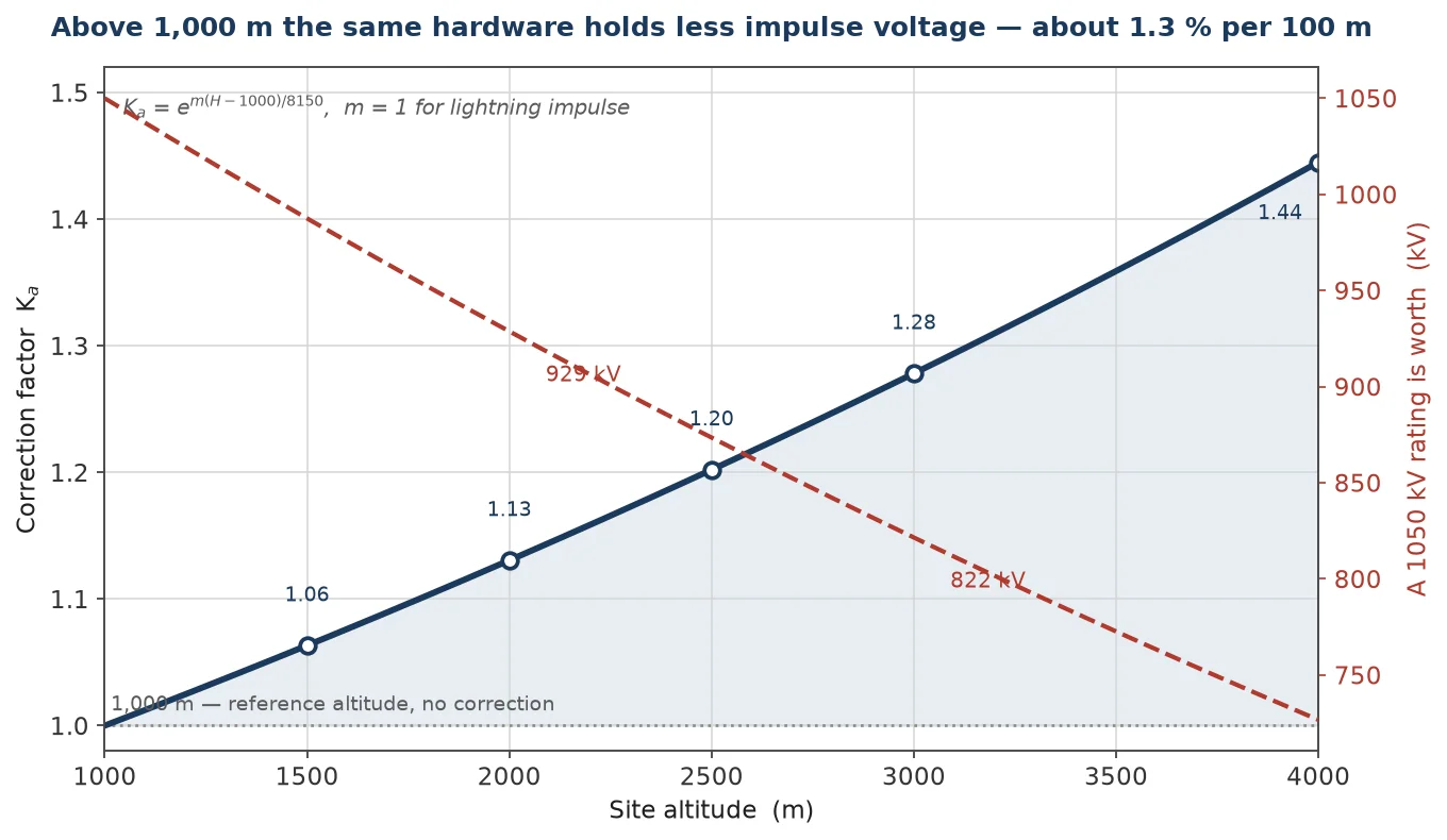
Altitude is the correction that catches most projects. Above 1,000 metres the air thins, the withstand voltage falls, and IEC 60071-2 applies a factor of the form Ka = em(H − 1000)/8150, with m equal to 1 for lightning impulse. The practical result is that a 1050 kV rating is worth less than 1050 kV on site.
Site altitude
Correction factor Ka
1050 kV rating becomes
Comment
1,000 m
1.000
1,050 kV
Reference altitude, no correction
1,500 m
1.063
988 kV
About 6 percent of margin consumed
2,000 m
1.130
929 kV
Equivalent to dropping one standard step
2,500 m
1.202
873 kV
One step below 950 kV, close to 850 kV
3,000 m
1.278
822 kV
Requires either a higher class or derating
4,000 m
1.445
727 kV
Beyond the range where a 245 kV unit is economic
The shorthand is roughly one and a third percent per hundred metres above 1,000 m, which is accurate enough for a first pass and wrong enough to matter at 3,000 m. Two commercial consequences follow. Either the equipment is specified one insulation level higher than the altitude-free design, or the supplier declares a reduced insulation level for the site and the buyer accepts that the nameplate no longer matches the standard table. Both are legitimate; silently ignoring the correction is not. The interaction with cold climate, where the same gas mass produces a lower pressure at minus thirty, is covered in the article on cold-climate and high-altitude operation.
About 1.3 percent per hundred metres above 1,000 m, until the nameplate no longer matches the table.
What 1050 kV buys you in metres of air
Impulse level translates directly into physical clearance, and that is where the cost sits. The correlation between rated impulse withstand and minimum phase-to-earth clearance in the unfavourable rod-structure arrangement is tabulated in IEC 60071-1 and repeated in installation standards.
LI withstand (kV peak)
Minimum clearance, rod-structure (mm)
Practical effect
550
1,100
123 kV class, compact substation layout
650
1,300
145 kV class
750
1,500
Upper end of 145 kV, lower end of 245 kV
850
1,700
245 kV, well-shielded substation
950
1,900
245 kV, average exposure
1,050
2,100
245 kV, line entrance or high isokeraunic level
Moving from 850 kV to 1050 kV costs 400 mm of clearance per phase-to-earth gap, and in a three-phase arrangement that is more than a metre of additional width across the bay. It also lengthens the porcelain, which raises the creepage available for pollution and usually raises the price. The decision is therefore not “higher is better” but “what does the insulation coordination study require, and does the site justify the step”. A 1050 kV breaker installed behind a 850 kV arrester in a shielded yard is buying margin it will never use. A 850 kV breaker at the end of an unshielded line is relying on the arrester to do work it was not sized for.
Reading the type test report
The report is the only artefact that matters. A catalogue page is a claim; the report is evidence, and it is worth reading in a fixed order so that nothing important is skipped.
What to look for
What good looks like
What should raise a question
Test object identification
Serial number, gas pressure at test, ambient temperature and humidity recorded
Only a type designation, no serial or gas data
Wave shape
Measured T1 and T2 on the oscillogram, within tolerance
Nominal 1.2/50 quoted with no trace
Number of applications
Fifteen per polarity, both polarities
Fewer applications, or flashovers described as conditioning
Test conditions
Dry and wet power-frequency tests reported separately
Only a dry result where the unit is for outdoor service
Insulation level declared
LI, PF and SI listed as a consistent set for one Um
Impulse and power-frequency values from different design tiers
Altitude statement
Rated altitude declared, or correction agreed in writing
Silence, with an assumption that 1,000 m applies
The full set of standards that govern these tests, and the editions that apply, is summarised in the guide to IEC 62271-1 and related SF6 breaker standards. One practical note on editions: IEC 62271-1 has been revised several times, and the dielectric clauses have moved. A report issued against a 2007 edition is still valid evidence of the design, but it may not satisfy a specification written against the 2017 text. Check the edition line before arguing about the numbers.
Choosing between 850, 950 and 1050 kV
The choice is made by the insulation coordination study, and the study answers three questions: what surge the arrester lets through, what margin the standard requires above that, and what the site exposure is. For a 245 kV system with a station-class arrester, the residual voltage at the impulse current of interest typically lands between 450 and 500 kV. A 850 kV level gives a protective margin of roughly 70 percent on that figure, and 1050 kV gives about 110 percent. Both exceed the minimum margin in IEC 60071-2 for well-shielded installations, which is why 850 kV is common in compact GIS yards and 1050 kV is common at line entrances.
Three site conditions push the decision upward regardless of what the study says: an isokeraunic level above about 40 thunderstorm days per year, a line entrance without a surge arrester within the first span, and a soil resistivity high enough that the earthing system cannot hold the tower footing resistance down. Each of those increases the energy and the steepness of what arrives, and none of them is visible in a standard load flow model.
The reverse also happens. On a 245 kV system where the transformer is protected by a closely located arrester and the yard is shielded by masts, a 950 kV level is a sensible compromise: one step of margin above the minimum, without paying for 400 mm of extra clearance per gap. Suppliers who quote only one level for every project are quoting a catalogue, not a design.
Conclusion
A 1050 kV impulse rating is a statement about a test, not about a site. Read it as three separate facts: the wave that was applied, the conditions under which it was applied, and the clearances that make it achievable. Then correct it for altitude, confirm that the power-frequency level belongs to the same design tier, and check that the report shows measured waveforms rather than nominal labels. That process turns a catalogue number into an engineering decision — and it usually reveals that the step between 850 and 1050 kV is being bought for reasons that have nothing to do with lightning.
If you are working through the insulation level for a 220 or 245 kV project, the SF6 circuit breaker guides cover the rest of the selection chain, from short-circuit duty to installation form. For a specific combination of impulse level, power-frequency level and altitude, send the site data and we will confirm which frame meets it without buying a clearance step the yard cannot use.
FAQ
Is 1050 kV BIL the same as 1050 kV lightning impulse withstand voltage?
Yes. BIL stands for basic impulse insulation level, the older American term, and it maps to the IEC rated lightning impulse withstand voltage. Both are peak values tested with a 1.2/50 µs wave. The American tradition uses 1.2 × 50 µs as well, so the numbers are directly comparable, although the standard tables differ slightly in the levels offered.
Why does a 245 kV breaker need both an impulse and a power-frequency test?
Because the two tests find different defects. The impulse test stresses air clearance and surface flashover in a few microseconds. The power-frequency test stresses the whole insulation system for a full minute and gives partial discharges time to develop, which is what catches voids, moisture and contamination. A unit that passes one and fails the other has told you something specific about its manufacturing quality.
Does altitude affect the impulse rating of an SF6 breaker?
It affects the external insulation and, through the standard’s conservative treatment, the declared rating. Internal insulation inside the sealed tank is set by gas mass, not by atmospheric pressure. Above 1,000 m, IEC practice applies a correction factor of about 1.13 at 2,000 m, so a 1050 kV unit is worth roughly 929 kV at that altitude unless the design is upgraded.
Is a chopped-wave test required for circuit breakers?
Not by IEC 62271-1, which specifies lightning impulse, switching impulse and power-frequency tests for switchgear. The chopped wave is a transformer duty under IEC 60076-3, aimed at inter-turn insulation. If a specification demands it for a breaker, ask which standard and whether a test report exists, because the requirement is usually inherited from a transformer specification.
How many impulses make a valid impulse test?
The IEC practice for a withstand test is fifteen applications of each polarity, with the insulation required to survive all of them. Reports showing fewer applications, or reporting flashovers that were accepted as conditioning, need a written explanation before they are treated as equivalent evidence.
The relative leak rate formula, a mass-balance worked example, the pressure-trend cross-check, what 0.5% vs 1% costs in CO2e and the fields an audit-ready annual report needs.
UHF, acoustic and IEC 60270 partial discharge detection for GIS compared: sensitivity and calibration limits, sensor placement, PD pattern signatures and how to scope online monitoring.
The seven landmarks of a healthy trip coil waveform, the three fault signatures that separate low voltage from mechanical binding, and how to record a baseline worth comparing years later.