Offshore Wind 66 kV Collection Systems: Breaker Selection for Salt Spray and Vibration
How 66 kV changed the collection system, what C5-M salt spray demands in measurable terms, and why the breaker boundary runs along the shoreline.
Read More
The circuit breaker test duties T10, T30, T60, T100s and T100a are the five breaking operations that prove a high-voltage breaker can actually interrupt short-circuit current — and the last of them, T100a, is the one that decides whether the rating on the nameplate is real. Every purchaser sees “40 kA” on a datasheet. Very few see the five duty numbers behind it, and fewer still can read the type test report that separates a breaker which has genuinely been proven at 40 kA from one whose 40 kA is a design calculation with a test certificate covering a milder condition.
This is the execution-level companion to the wider SF6 circuit breaker testing overview: here the focus is narrow — what each duty is, why the asymmetrical one is the hard one, what the 45 ms time constant does to the arithmetic, and which lines in the report you should actually read. If you are evaluating high-voltage SF6 circuit breakers and the vendor has sent a 200-page type test report, this is the map.
A single breaking test proves very little, because a breaker’s difficulty is not monotonic in current. At low current the arc is weak and easy to extinguish but the energy in the circuit can produce severe recovery voltage. At very high current the arc is violent but the current zero arrives with a steep rate of change of current that the interrupter is designed around. Somewhere in between there is a range where the interrupter is at its weakest, and the standard’s answer is to test a ladder of currents rather than a single point.
Hence five duties. T10, T30 and T60 at 10, 30 and 60 percent of the rated short-circuit breaking current cover the lower and middle range, where the arc energy is modest and the interrupter’s behaviour is dominated by its dielectric recovery. T100s is the full symmetrical current — the headline case everyone quotes. T100a is the full current with a prescribed direct-current offset, which is the same current but a very different amount of energy delivered into the arc.
| Duty | Breaking current | DC component at contact separation | What it is really testing |
|---|---|---|---|
| T10 | 10% of rated Isc | Not more than 20% | Low-current interruption, dielectric recovery with a weak arc |
| T30 | 30% of rated Isc | Not more than 20% | Transition range where many designs are least stable |
| T60 | 60% of rated Isc | Not more than 20% | Upper middle range, thermal and dielectric combined |
| T100s | 100% of rated Isc | Not more than 20% | Full symmetrical breaking capability |
| T100a | 100% of rated Isc | Prescribed minimum, 52% for 50 Hz with a 45 ms time constant | Full asymmetrical breaking — the thermal and erosion worst case |
The 20 percent ceiling on the “symmetrical” duties is not a tolerance, it is the definition: a test only counts as symmetrical if the offset has largely decayed by the time the contacts part. T100a is the mirror image — it requires the offset to still be substantial at contact separation, which is why it cannot be substituted by a second T100s.
The standard explanation, repeated in most summaries, is that T100a is harder because the direct-current offset steepens the rate of change of current at the zero crossing, making the arc harder to extinguish thermally. That explanation is wrong, and it is worth understanding why, because the correct version tells you what to look for in a test report.
With a DC offset, the current is shifted upward (or downward) by an amount that decays exponentially. The interruption happens at the zero crossing of the total current, and that zero is displaced away from the natural zero of the alternating component. At the displaced zero, the alternating component is not passing through its own zero but through a value equal to the offset — which means its rate of change is reduced by exactly the factor that describes how far it has been displaced. With a 52 percent offset at contact separation, the alternating component at the displaced zero has fallen to about 85 percent of its peak, so the rate of change of current at the moment of interruption is roughly 85 percent of the symmetrical value. T100a is gentler on the thermal-reignition margin, not harsher.
What makes it the hard duty is everything else. The current spends far longer near its peak, so the charge carried through the arc is much larger for the same arcing time. Arc energy in an SF6 interrupter scales with that charge, because the arc voltage is roughly constant with current. More energy means higher gas pressure in the heating volume, more nozzle ablation, more contact erosion, and a hotter, more ionised residue sitting in the gap at the moment the breaker has to hold off the recovery voltage. The breaker passes or fails T100a on pressure rise and contact survival, not on di/dt.
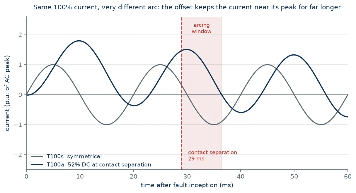
There is a second-order effect that matters for the test itself. In the fully offset case the alternating component has one large half-cycle and one small one, and a breaker that separates too late to catch the large one will interrupt on the smaller loop that follows. That is why the standard defines T100a by the offset at contact separation rather than by the instant of fault inception: specifying the closing angle would make the test depend on the breaker’s own opening time, and no two designs would be tested at the same condition.
The DC component decays exponentially with a time constant that the standard fixes for the voltage class. For transmission-class breakers the usual value is 45 ms; 60 ms appears in some specifications and in networks with a high X/R ratio, and generator circuit breakers use longer values again. The difference is not cosmetic.
The decay is simple enough to compute by hand: the offset at time t is the initial offset multiplied by e−t/τ. With τ = 45 ms the offset is down to 51 percent at 30 ms and 26 percent at 60 ms. With τ = 60 ms it is still 51 percent at 40 ms and 37 percent at 60 ms. A breaker whose contacts part 30 ms after fault inception therefore faces a very different offset depending on which time constant the network actually has.
| Time after fault inception | DC component, τ = 45 ms | DC component, τ = 60 ms |
|---|---|---|
| 0 ms | 100% | 100% |
| 20 ms | 64% | 72% |
| 30 ms | 51% | 61% |
| 40 ms | 41% | 51% |
| 60 ms | 26% | 37% |
| 75 ms | 19% | 29% |
Run the numbers backwards and the 52 percent figure becomes informative: with τ = 45 ms, an offset of 52 percent corresponds to a contact separation at about 29 ms after fault inception. That is a realistic figure for a breaker with a 20 ms to 25 ms minimum opening time plus a few milliseconds of arcing, which is exactly why the standard picked it. The duty is calibrated to a real breaker, not to a worst case that no design could survive.
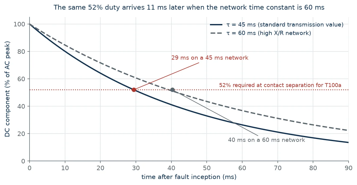
The practical consequence for a project is straightforward. If your network’s time constant is 60 ms rather than 45 ms — which happens in networks with long transmission corridors and little generation nearby — then a breaker tested to the 45 ms T100a condition has been tested at a lower offset than it will meet in service at the same contact separation. The rated breaking current may still be adequate, but the erosion per operation will be higher than the endurance class assumes. This is one of the few places where a standard-compliant breaker can be genuinely undersized for the application without anyone having made an error.
The report is where the five duties become evidence or stay marketing. The following lines are the ones worth checking, and each of them is a place where a report can be technically valid and still not support the claim being made for it.
| Line in the report | What to check | Common problem |
|---|---|---|
| Test voltage | Was the duty performed at the rated voltage of the breaker? | Duties performed at reduced voltage, then extrapolated |
| Test current | Percentage of rated Isc, and whether the AC component was at 100% | Current achieved by raising voltage rather than by the test circuit |
| DC component at contact separation | The measured percentage, not just the target | T100a run with a lower offset than the standard requires |
| Arcing time | Consistent with the declared minimum opening time | Long arcing times that flatter the TRV but raise the energy |
| Transient recovery voltage | Actual TRV shape against the specified envelope | Missing the specified time delay for the installation |
| Number of operations | The full sequence, including CO where the standard requires it | A single O reported as if it covered the sequence |
| Post-test condition | Contact and nozzle inspection, not only a pass verdict | No erosion data, so endurance cannot be inferred |
The single most common weakness is the first line. A breaker rated for 126 kV that was tested at 72.5 kV has been tested against a milder recovery voltage, and the TRV severity is not linear in voltage — it depends on the surge impedance of the test circuit as well as the voltage. When a report shows a test voltage below the rated voltage, the correct question is not “was it extrapolated?” but “what is the evidence for the rated condition?”.
Erosion data is the second gap. A report that says “pass” without contact mass loss or nozzle diameter change tells you the breaker survived; it does not tell you how much of its life one T100a consumed. For a project that expects several fault clearings per year over twenty years, that number is worth more than the pass verdict. A breaker like the LW36-126 with 40 kA breaking capacity is a case where the headline figure is well supported; the useful question is what one 40 kA asymmetrical operation costs in contact life. At the 72.5 kV level the same question attaches to the LW9-72.5 4000 A high breaking capacity unit, where the higher continuous current and the shorter contact gap put more of the duty into the nozzle.
The five duties are all terminal faults — the fault is at the breaker terminals and the recovery voltage is the standard one. Several real conditions sit outside that envelope, and each has its own test duty that must be specified separately.
Short-line fault. When the fault is a few hundred metres down an overhead line, the line side of the breaker sees a travelling wave that produces a sawtooth recovery voltage with a very high initial rate of rise. The L90 and L75 duties exist for this, and a breaker that passes T100a comfortably can still be marginal on L90 because the stress is in the first few microseconds. The short-line fault duty is the one to add for any breaker protecting an overhead line.
Out-of-phase switching. Breaking with the two sides of the circuit out of synchronism means half the current at twice the voltage, which is a dielectric duty rather than a thermal one and is tested as OP1 or OP2. This is covered in detail in the companion piece on out-of-phase and close-open duties, and it is the clearest example of a rating that no amount of terminal-fault testing can substitute for.
Capacitive switching. Line charging, cable charging and capacitor bank duties are low-current but carry restrike risk and, for back-to-back banks, high-frequency inrush. The C1 and C2 classes are separate from the T duties and separate from each other; the capacitive current switching requirements are not implied by a good T100a result.
Critical current. The T10 to T60 ladder exists partly to find the range where a design is weakest, but for some interrupter types the critical current is below 10 percent. Where the application involves switching small inductive currents — unloaded transformers, reactors — the relevant evidence is a specific test at that current, not the ladder.
The productive version of this whole subject fits in a short paragraph of a purchase specification. Name the standard and the edition; state the rated short-circuit breaking current and the time constant the network actually has; require the full duty set T10 through T100a rather than “type tested to IEC 62271-100”; require the duties to have been performed at rated voltage; and ask for the post-test contact and nozzle inspection data, not only the verdict.
Add the special duties the application needs — L90 for overhead lines, OP1 or OP2 for ties and busbar sections, C2 for capacitor banks — and state them as requirements rather than assuming the vendor has covered them. A vendor who has the reports will send them without argument. A vendor who does not will negotiate, and that negotiation is the information you were looking for.
None of this is exotic. It is the difference between buying a breaking capacity and buying evidence for one. Where the project also involves insulation coordination and the wider standards framework around IEC 62271-100, the same discipline applies: the number on the datasheet is a claim, and the duty set is the proof.
Both are at 100 percent of the rated short-circuit breaking current. T100s is symmetrical, with the DC component limited to 20 percent at contact separation; T100a is asymmetrical, with a prescribed minimum offset at contact separation — 52 percent for 50 Hz with a 45 ms time constant. T100s proves the current can be interrupted; T100a proves it can be interrupted with a large offset still present, which is the thermal and erosion worst case.
Because the maximum offset depends on the instant the fault starts, which is random, and because a breaker that separates late enough will interrupt on a small loop rather than the large one. Defining the duty by the offset at contact separation removes both variables and makes the test reproducible across designs with different opening times.
Lower. The offset displaces the zero crossing away from the natural zero of the alternating component, and at the displaced zero the alternating component is passing through a value equal to the offset rather than through zero. With a 52 percent offset the rate of change is about 85 percent of the symmetrical value. The difficulty of T100a is arc energy and pressure, not a steeper current zero.
Usually yes, with a caveat. The rated breaking current remains valid, but at the same contact separation the offset will be higher than the test condition, so the arc energy and contact erosion per operation will be greater than the endurance class assumes. For a network with a long time constant and a high expected fault frequency, ask for the duty at the actual time constant.
Then the asymmetrical capability is unproven. This is common in older reports and in reports prepared for a different market. It does not mean the breaker cannot do it — most modern SF6 interrupters can — but it means you are relying on design margin rather than evidence, and the price should reflect that.
Five duties exist because a breaker’s hardest moment is not always at its highest current, and because the two ways an interrupter fails — thermally and dielectrically — peak at different points on the current axis. T10 through T100s cover the dielectric and low-current behaviour; T100a covers the energy. A specification that asks only for the headline current has bought one of the five, and usually not the one that decides whether the breaker survives twenty years of faults.
The SF6 circuit breaker technical library covers the adjacent duties and the standards behind them, and the engineering team can review a specific type test report against a project’s fault level and time constant if you send both across.