Offshore Wind 66 kV Collection Systems: Breaker Selection for Salt Spray and Vibration
How 66 kV changed the collection system, what C5-M salt spray demands in measurable terms, and why the breaker boundary runs along the shoreline.
Read More
A short time withstand current circuit breaker rating and a peak withstand rating look like the same number written two ways. They are not. One is a thermal budget expressed in square ampere-seconds; the other is a mechanical strength limit expressed in a single instantaneous peak. On a typical 126 kV unit the datasheet reads 40 kA for 3 s and 100 kA peak, and the two figures describe two entirely different ways the breaker can be destroyed — one by heat soaking into contacts and conductors over seconds, the other by electromagnetic force trying to tear the busbar apart in the first ten milliseconds.
Buyers mix them up constantly. A specification that asks for “a 100 kA breaker” has confused a peak withstand value for a breaking capacity, and the enquiry that follows is unanswerable. A specification that asks for 40 kA/1 s when the project needs 40 kA/3 s has quietly halved the thermal capability while looking identical on the comparison sheet. This article separates the two ratings, works through the arithmetic that connects them, and shows where the standard’s own assumptions stop being conservative. If you are comparing high-voltage SF6 circuit breakers for a substation with a high through-fault duty, these are the two lines that decide whether the unit survives a stuck feeder.
Both ratings describe the breaker in the closed position carrying fault current that it is not required to interrupt — current passing through on its way to a fault cleared by something else. That is the whole point of the pair, and it is why neither is covered by the breaking capacity rating. A breaker that opens a 40 kA fault has done its job in 40 to 60 milliseconds. A breaker that carries 40 kA for three seconds is doing something else entirely: it is a conductor, and it is being asked to stay a conductor.
The two ways it stops being a conductor are unrelated. Heat is slow and cumulative; it raises the temperature of the current path until something anneals, softens or degrades. Force is instantaneous and structural; it appears at the first peak of the asymmetrical current and either the assembly holds or it does not. Nothing about passing the thermal test gives evidence for the mechanical one, which is why the standard declares both.
| Attribute | Rated short-time withstand current | Rated peak withstand current |
|---|---|---|
| Quantity declared | r.m.s. current, kA | Instantaneous peak, kA |
| Duration | 1 s or 3 s (declared) | No duration — one half-cycle |
| Typical value, 40 kA unit | 40 kA for 3 s | 100 kA (2.5 × 40) |
| Physical mechanism | I²t heating of contacts, conductors, springs | Electrodynamic force between parallel current paths |
| First thing to fail | Contact plating, spring temper, gaskets, nozzle | Support insulators, busbar bracing, contact blow-off |
| How it is verified | Temperature measurement after a timed current test | Withstand without damage at the declared peak |
| Binding constraint in practice | Only when protection is slower than the declared duration | Almost always, at high fault levels |
That last row is the practical conclusion of the whole article, and it surprises people. In a normal distribution or sub-transmission substation, the thermal rating is so generous that it never binds; the mechanical rating is what sets the busbar bracing and the insulator strength. The exception is the through-fault case with slow backup protection, which is exactly the case that the 3 s duration exists to cover.
The rating is a promise about temperature. IEC 62271-100 requires that after carrying the rated short-time withstand current for the rated duration, the breaker still works: no contact welding, no loss of spring temper, no gasket damage, no change in the dielectric performance of the gas space. The temperature limits behind that promise are the ordinary material limits — copper and its alloys around 200 to 250 °C for short-time duty, silver plating well below that before it diffuses into the substrate, and elastomer seals that start to take a permanent set far earlier than any metal.
Two details matter and are usually skipped. The first is that the heating is not uniform. Current concentrates at the contact interface, where the actual contact area is a small fraction of the apparent area, so the contact spot runs hotter than the conductor it sits in. The second is that the gas inside the interrupter is part of the thermal path: an SF6 breaker relies on convection through the gas to move heat off the contact assembly, and that convection depends on density, which depends on temperature. The system is not linear, which is why the standard tests rather than calculates.
For engineering purposes the thermal capability is a single number. A 40 kA/3 s rating is 40² × 3 = 4,800 kA²·s of thermal budget. Any fault of current I lasting t consumes I²t from that budget, and the check is simply whether the consumption fits.
The useful consequence is that the duration is not fixed — it is a budget at rated current. Halve the current and you quadruple the time you can carry it. Double it and you have a quarter of the time. That relationship is the whole basis of using a 3 s breaker on a 2 s protection scheme, and it is also the basis of the trap in the next section.
| Fault current | Permissible duration at that current | Comment |
|---|---|---|
| 40 kA (rated) | 3.0 s | The declared rating; no margin by definition |
| 31.5 kA | 4.8 s | Typical 126 kV busbar fault level |
| 25 kA | 7.7 s | Distribution substation fault level |
| 20 kA | 12.0 s | Beyond any realistic protection time |
| 50 kA | 1.9 s | Already above the 40 kA breaking capacity |
| 69.3 kA | 1.0 s | Arithmetically valid, mechanically impossible — see below |
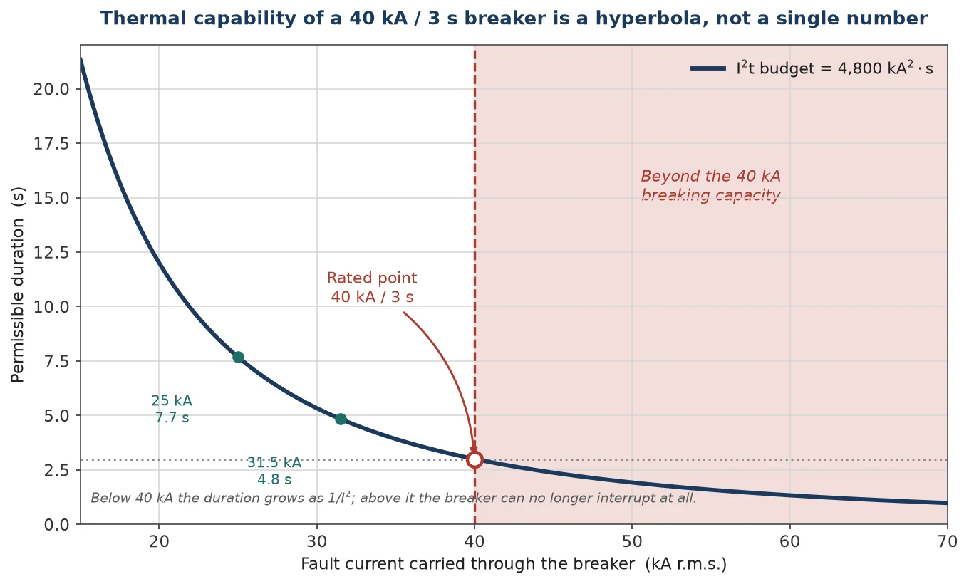
The curve is a hyperbola, and reading it as one is the whole skill. At the left it flattens toward “indefinitely”; at the right it drops into the region where the current itself is beyond what the breaker can interrupt, and the thermal calculation stops being the relevant question.
Because the budget is fixed, a 40 kA/3 s unit converts to 40 × √3 = 69.3 kA for 1 s. This figure appears in tender comparisons, in vendor brochures and in more than a few specifications, and it is a number that should never be used to select anything.
Three things go wrong with it. First, it is arithmetic, not a rating. The standard declares one rated duration — 1 s or 3 s — and the other value is a derived figure that no laboratory has verified and no manufacturer has warranted. Second, it is bounded by the breaking capacity: a 40 kA breaker cannot interrupt 69.3 kA no matter what its I²t budget says, so the derived value is unusable in the only region where it would matter. Third, and most importantly, it is bounded by peak withstand. At 69.3 kA r.m.s. the peak is 173 kA, and a breaker built for 100 kA will fail mechanically long before it fails thermally.
Run the reverse conversion — a 40 kA/1 s unit described as 23 kA for 3 s — and the same three objections apply in the other direction, with one addition. Scaling a short duration up to a long one assumes the adiabatic approximation still holds, which it does not: at 3 s a meaningful amount of heat has left the contact assembly by conduction and convection, so the true long-duration capability is somewhat better than I²t scaling predicts. The safe direction of error is the one nobody uses.
The practical rule: quote the declared rating, compare declared ratings, and use I²t scaling only to check whether an actual fault of a known current and known clearing time fits inside the declared budget. That is what the budget is for.
Peak withstand is a structural claim. It says the closed breaker, with its contacts touching and its current path carrying the first asymmetric peak of a fault, will not be deformed, will not blow its contacts apart, and will not crack an insulator. The number on the datasheet is not a physical constant of the design; it is a convention, and the convention is 2.5 times the short-time withstand current at 50 Hz and 2.6 times at 60 Hz.
The factor is the peak of a fully offset asymmetrical current, evaluated at the first major loop. For a fault closing at voltage zero the current is
i(t) = √2 · I · (e−t/τ − cos ωt)
and the first peak arrives one half-cycle after the fault starts. IEC 62271-100 assumes a d.c. time constant τ of 45 ms at 50 Hz, which is an X/R of about 14. At t = 10 ms the exponential has decayed to 0.80, the cosine term is −1, and the peak works out to √2 × 1.80 = 2.55 times the r.m.s. symmetrical current. That is rounded to 2.5. At 60 Hz the assumed time constant is 60 ms and the half-cycle is 8.33 ms; the exponential is 0.87 and the result is 2.64, rounded to 2.6.
So the factor is an assumption about the network, not a property of the breaker. That distinction matters most exactly where it is least often checked.
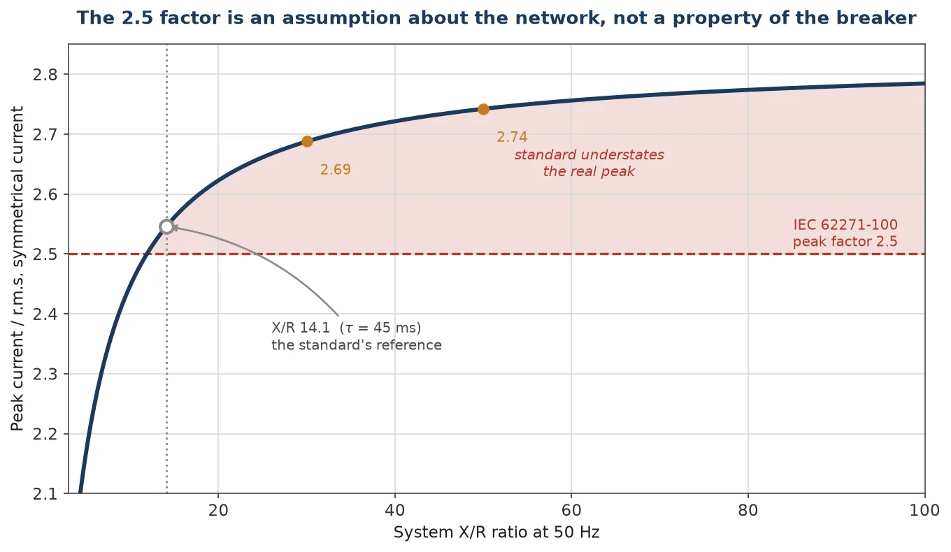
A remote 126 kV substation fed through a long line might have an X/R of 5, giving a real peak factor of about 2.17 — the standard’s 2.5 is comfortably conservative and the busbar is over-braced, which is harmless. A substation close to a large generator, or fed directly through a large transformer, can reach an X/R of 30 or more, where the real peak factor is 2.69. There the standard’s 2.5 understates the force by around 8 percent in current, which is 16 percent in force, because force goes with the square. A busbar designed exactly to the 2.5 assumption in that station is not designed with margin; it is designed with a deficit.
| System X/R at 50 Hz | d.c. time constant | Real peak factor | Against the 2.5 assumption |
|---|---|---|---|
| 5 | 16 ms | 2.17 | Conservative by 13% |
| 10 | 32 ms | 2.45 | Conservative by 2% |
| 14 | 45 ms | 2.55 | The standard’s reference case |
| 20 | 64 ms | 2.62 | Understated by 5% |
| 30 | 96 ms | 2.69 | Understated by 8% |
| 50 | 159 ms | 2.74 | Understated by 10% |
Two parallel conductors carrying current in the same direction attract each other, and the force per metre is
F = 2 × 10⁻⁷ × I² / d
with d the spacing in metres. For a 100 kA peak at 300 mm spacing that is 6.7 kN per metre of busbar — roughly the weight of a small car hanging off every metre, applied and released in 10 ms. Move the conductors to 500 mm and the force drops to 4.0 kN per metre, which is why busbar spacing in high-fault stations is a structural decision rather than a layout preference. In a three-phase arrangement the middle conductor carries the worst of it, because it is pushed by both neighbours in the same half-cycle.
Inside the interrupter the same physics acts on a much smaller scale with a much worse consequence. The contacts are held closed by spring pressure measured in hundreds or low thousands of newtons; the electromagnetic force during a fault peak pushes them apart. When the blow-off force approaches the contact pressure the contacts separate slightly, an arc establishes, and the contact faces weld or erode at a point where the breaker is supposed to be doing nothing at all. This is one of the reasons a breaker’s short-time withstand current is not automatically equal to its breaking capacity, and why the two are declared separately.
A related number that causes confusion is the rated short-circuit making current, which is also quoted as a peak and also uses the 2.5 factor. The two are different duties. Peak withstand is a static structural check on a closed breaker. Making current is a closing operation: the contacts approach, the gap breaks down before they touch, an arc burns across the closing gap with no gas blast to cool it, and the contacts then slam together and bounce. Same arithmetic, entirely different test, and a breaker that passes one has demonstrated nothing about the other.
The connection to the rest of the specification is worth following, because the mechanical rating is where several other declared values originate. The IEC 62271-100 ratings structure derives peak withstand from short-time withstand by the fixed factor; the breaking-capacity test duties use the same asymmetry assumption to build the T100a waveform; and the type and routine tests verify each of them separately. Read as a set they are internally consistent. Read as a single “kA” number they are not.
Take a 126 kV substation with a 31.5 kA busbar fault level, a 40 kA/3 s breaker, and a feeder protection that clears in 80 ms with a 50 ms relay time. The thermal duty is 31.5² × 0.13 = 129 kA²·s against a budget of 4,800 — a margin of 37 times. The thermal rating is irrelevant to this project, and any time spent comparing 1 s and 3 s variants is wasted.
Now suppose the same substation has a busbar section breaker that must carry through-fault current while a stuck feeder breaker is cleared by the upstream protection, at 1.5 s. Duty is 31.5² × 1.5 = 1,488 kA²·s, a margin of 3.2 times. Still comfortable, but the number has moved by an order of magnitude, and a 1 s rated unit at 40 kA/1 s — budget 1,600 kA²·s — would have a margin of 1.08, which is no margin at all once measurement tolerance and relay reset are included. This is the scenario the 3 s duration exists for, and it is the only scenario where the choice between 1 s and 3 s changes the outcome.
The mechanical check is the one that actually constrains the design. At 31.5 kA the peak is 78.7 kA by the standard factor, or 84.7 kA at X/R 30. Force at 300 mm spacing is 4.1 kN/m or 4.8 kN/m respectively. Support spacing and insulator cantilever rating have to be chosen for the second figure if the station is generator-adjacent, and the 2.5-based calculation will not tell you so.
Four line items cover the two ratings properly, and all four are routinely missing.
Declare the duration explicitly. “40 kA/3 s” not “40 kA”. A 1 s unit and a 3 s unit are different products with different conductor sections, and a vendor quoting the cheaper one against an ambiguous line item is not being dishonest — the specification allowed it.
Declare peak withstand as a separate value. Do not let it be inferred. If the station’s X/R is above 20, say so and ask the vendor to confirm the peak against the real value rather than the standard factor.
State the through-fault scenario. Whether the breaker is ever required to carry fault current while another device clears, and for how long, decides the duration. A radial feeder breaker that always trips its own fault does not need 3 s.
Ask for the temperature rise test report. The short-time withstand test result should show the measured temperatures and the limits applied, not just a pass. A report that lists only the current and the duration has not demonstrated anything about the margin.
On the datasheet, yes — that is the standard’s declared relationship at 50 Hz, and 2.6 at 60 Hz. Physically, no: the real peak depends on the network’s X/R ratio, and the 2.5 factor corresponds to an assumed 45 ms time constant. For stations with X/R above about 20 the real peak is higher than 2.5 times, and the busbar should be checked against the real value.
Only if the actual fault current is low enough that I²t still fits. A 40 kA/1 s unit has a 1,600 kA²·s budget, so at 31.5 kA it lasts 1.6 s, not 3 s. If the through-fault time is genuinely 3 s at 31.5 kA the unit is undersized by a factor of two, and no amount of interpreting the datasheet changes that.
Because the two are limited by different things. Breaking capacity is set by the interrupter’s arc-control capability; short-time withstand is set by the conductor and contact cross-sections. A design with generous conductors and a compact interrupter can carry more than it can interrupt, which is legitimate and is declared honestly on the datasheet. The reverse also occurs.
Not in any way that shows up in normal operation. The rating only matters during the fault condition it describes, and a breaker rated for 100 kA peak in a station where the maximum peak is 60 kA has no advantage over one rated 80 kA. The money is better spent on the interrupter, the mechanism or the endurance class.
It passes the rated current for the rated duration through a closed breaker and then measures temperatures at defined points, checks the contacts for welding, and repeats a dielectric test to confirm nothing has degraded. The pass criterion is temperature limits and post-test condition, not current alone. A test report that gives the current and duration but no temperatures has not shown you the result.
Directly. The peak withstand value is the input to the substation layout calculation for support spacing and insulator cantilever load, and the short-time withstand value is the input to the earthing conductor sizing. Both are switchgear-level numbers that the breaker declares and the station design consumes.
Short-time withstand is a thermal budget: 40 kA for 3 s is 4,800 kA²·s, and any fault fits or does not fit inside it. Peak withstand is a structural limit: 100 kA is 2.5 times 40 kA by the standard’s assumed 45 ms time constant, and it is the number that decides busbar bracing and insulator strength. Neither is covered by the breaking capacity rating, and neither substitutes for the other.
The trap is the conversion. Scaling 3 s to 1 s by √3 produces a number that is arithmetic rather than a rating, and that is bounded by breaking capacity and by peak withstand before it is ever bounded by heat. Quote the declared duration, compare declared durations, and use I²t only to check a known fault against a known budget.
The 40 kA/3 s short-time withstand version of the 126 kV breaker exists precisely for the through-fault case, and the 3150 A rated current and 72.5 kV 4000 A porcelain column units carry the same ratings logic at their own voltage and current levels. For EHV work the 252 kV breaker declares its peak and short-time values against a much higher fault level, where the mechanical check stops being a formality. Our SF6 circuit breaker technical library covers the surrounding ratings, and the engineering team can run the I²t and peak check against your fault level and protection times if you send both across.