Offshore Wind 66 kV Collection Systems: Breaker Selection for Salt Spray and Vibration
How 66 kV changed the collection system, what C5-M salt spray demands in measurable terms, and why the breaker boundary runs along the shoreline.
Read More
Back to back capacitor bank switching is the duty that quietly destroys more breakers than any short circuit. Two banks share a busbar. One is already energised at full charge. The second is closed onto it, the gap between the contacts is bridged while the voltage difference across that gap can approach twice peak, and the only thing limiting the resulting current is the loop inductance between the two banks — a few tens of microhenries of busbar. What flows is not a fault current in the ordinary sense. It is a high-frequency discharge that peaks in the tens of kiloamperes within a millisecond or two and is entirely capable of welding the arcing contacts shut on the very first operation.
That is why a breaker rated for 40 kA of symmetrical short-circuit current can still fail on a 20 MVar capacitor bank. The two duties are rated separately, tested separately, and in most badly written specifications confused with each other. What follows is the arithmetic that tells you whether an installation sits inside or outside the standard rating, why a damping reactor changes the answer by two orders of magnitude, and what contact welding looks like when it happens. If you are specifying high-voltage SF6 circuit breakers for a switched capacitor installation, these are the numbers that decide whether the equipment survives twenty years or twenty operations.
Energising a single isolated bank is a comparatively gentle event. The inrush current is limited by the source impedance behind the busbar — the transformer leakage reactance plus the supply system — which is large. Typical single-bank inrush frequencies land between 300 Hz and 1,000 Hz with peaks in the 5 kA to 15 kA range, and the current decays over several cycles. The breaker sees one modest high-frequency excursion and recovers.
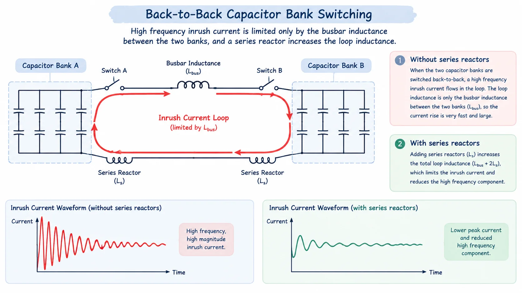
Back-to-back switching removes the source impedance from the circuit entirely. The discharge path runs from the charged bank through the closing contacts into the second bank and back, and the only impedance in that loop is the busbar, the cable between the two banks, and any series reactor deliberately installed. Busbar inductance is measured in microhenries. A microhenry against a few microfarads produces a resonant frequency in the tens of kilohertz, and the same small inductance that permits the high frequency also permits a very large peak current. When a manufacturer quotes a back to back capacitor bank switching rating, it is this loop — not the source — that the number describes.
| Characteristic | Single bank energisation | Back-to-back switching |
|---|---|---|
| Limiting impedance | Source + transformer leakage reactance (milliohms to ohms) | Busbar and cable inductance between banks (microhenries) |
| Typical inrush frequency | 300 – 1,000 Hz | 5,000 – 20,000 Hz without reactors |
| Typical peak inrush | 5 – 15 kA | 20 – 60 kA depending on bank size and spacing |
| Duration of the high-frequency component | Several cycles | 0.2 – 1 ms (one to three oscillations) |
| Governing standard rating | Rated capacitive switching current (e.g. 400 A) | Rated back-to-back capacitor bank inrush making current |
The duration column is the part that catches people out. The whole event is over before any protection relay has finished sampling. There is no chance to trip on it, no chance to limit it, and no time for the mechanism to react. Everything depends on the breaker having been designed and tested for the duty in advance.
Two banks of capacitance C1 and C2 connected through a loop inductance L behave as a series LC circuit driven by whatever voltage difference exists across the closing gap at the instant the contacts touch. The equivalent capacitance is the series combination:
Ceq = (C1 × C2) / (C1 + C2)
For two identical banks this reduces to half of one bank’s capacitance, which is the case most installations actually present. The oscillation frequency and the first peak follow directly:
f = 1 / (2π √(L × Ceq))
î = V̂gap × √(Ceq / L)
where V̂gap is the peak voltage across the gap at contact touch. That last term is where the spread in real results comes from. If the second bank is fully discharged and the contacts touch at the instant the source voltage passes through its peak, V̂gap is one times peak phase voltage. If the second bank is carrying trapped charge of opposite polarity from a recent opening, the gap voltage doubles and so does the peak current. This is why two nominally identical installations can report inrush figures that differ by a factor of two, and why point-on-wave closing is worth discussing later.
Take a 72.5 kV busbar carrying two 20 MVar banks, each with a 6% series reactor, installed in adjacent bays. Phase voltage is 72,500 / √3 = 41.86 kV RMS, so the peak is 59.2 kV. Each bank draws 159 A at rated voltage, giving a capacitive reactance of 263 Ω and therefore a capacitance of 12.1 µF. Two identical banks in series give Ceq = 6.05 µF.
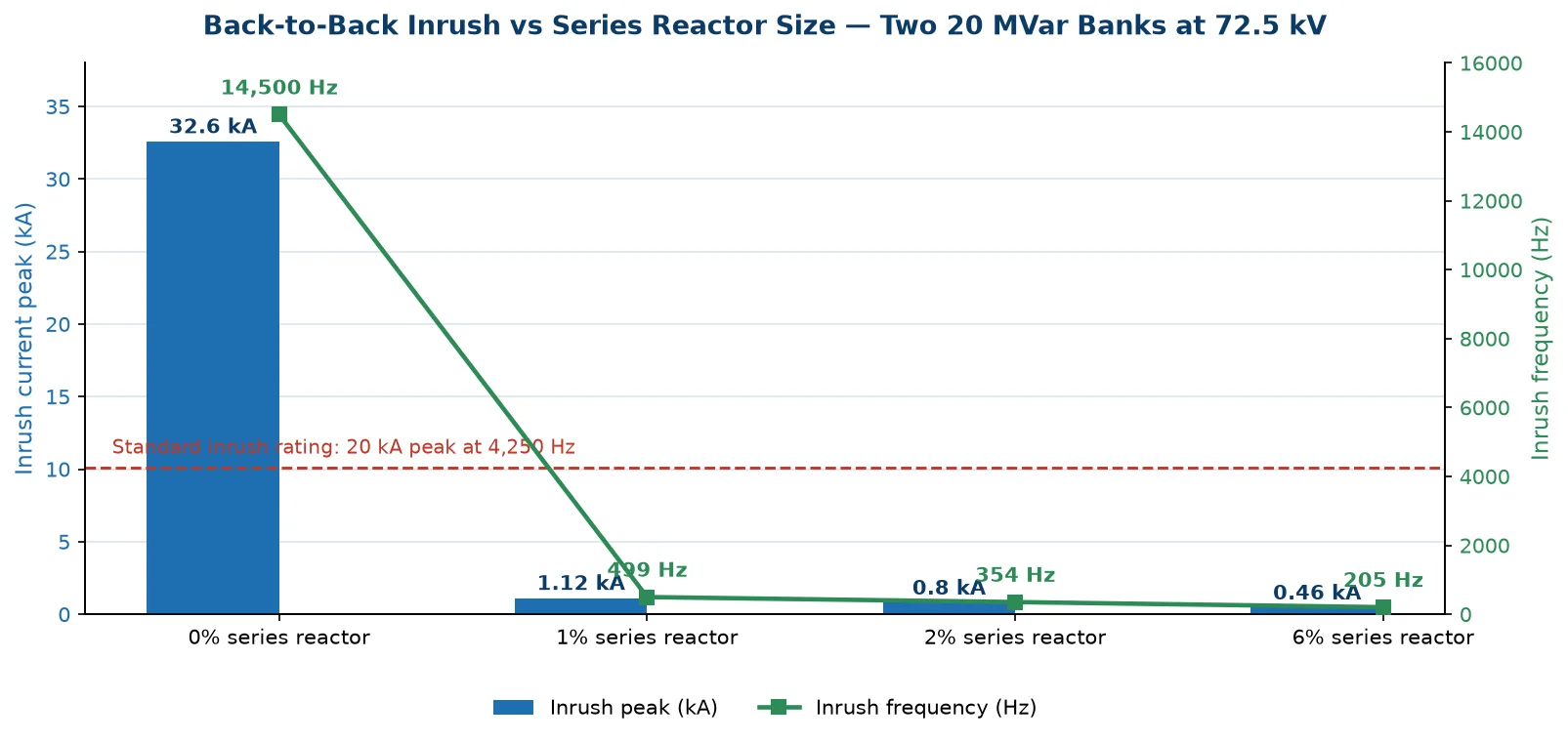
Without any reactor, the loop is busbar only — call it 20 µH. Substituting gives a frequency of 14.5 kHz and a first peak of 32.6 kA. That single number is the whole argument. A breaker whose standard back-to-back inrush rating is 20 kA peak at 4,250 Hz is being asked to make 32.6 kA at 14.5 kHz, and if the second bank happens to be at opposite trapped charge the peak reaches 65 kA. The rating is exceeded on both axes simultaneously.
Now fit the 6% reactors. Each reactor presents 15.8 Ω, which at 50 Hz is 50.2 mH. The back-to-back loop passes through both reactors, so L becomes roughly 100 mH. The frequency collapses to 205 Hz and the first peak to 460 A. Same banks, same busbar, same breaker — a seventy-fold reduction in peak current from two pieces of iron.
| Series reactor per bank | Loop inductance | Inrush frequency | First peak (bank 2 discharged) | First peak (opposite trapped charge) |
|---|---|---|---|---|
| None (busbar only) | ≈ 20 µH | 14.5 kHz | 32.6 kA | 65 kA |
| 1% | ≈ 16.8 mH | 499 Hz | 1.12 kA | 2.24 kA |
| 2% | ≈ 33.5 mH | 354 Hz | 0.80 kA | 1.60 kA |
| 6% | ≈ 100 mH | 205 Hz | 0.46 kA | 0.92 kA |
Note what the table is really saying. Almost all of the benefit arrives with the first one or two percent. A 1% reactor already brings the peak inside any standard rating. The move from 2% to 6% buys a further 40% reduction in peak current, but its main justification is detuning rather than inrush — the 6% value places the bank-and-reactor resonance below the fifth harmonic so the bank does not amplify harmonic currents present on the busbar. Size reactors for inrush and for detuning separately, and do not assume one requirement covers the other.
Contact welding is not a single event. It is the end of a chain that begins with the electromagnetic force between two current-carrying contacts and finishes with a metallurgical joint that the opening spring cannot break.
Current flowing through a contact bridge generates a repulsive force proportional to the square of the current. At 32 kA peak that force is not a rounding error — in a typical 72.5 kV interrupter it can approach or exceed the contact spring preload plus the residual closing force from the mechanism. When the net force reverses, the contacts lift by a fraction of a millimetre. A fraction of a millimetre is enough for the dielectric to break down at a few hundred volts, an arc strikes, and the contacts re-close into their own molten pool.
Even without blow-off, a closing operation at 1.5 m/s to 2 m/s produces two to five bounces in the first millisecond. Each bounce is a make-break-make sequence at a few thousand amperes, and each one strikes a fresh arc. Because the inrush current is oscillating at 14 kHz, the current passes through zero every 34 µs. The arc extinguishes briefly at each zero crossing, the contact gap is still tiny, the recovery voltage across that gap is high because the oscillation is still running, and it restrikes. The result is a rapid series of short, high-power arcs at the contact surface — precisely the condition that produces deep erosion craters and, if the surfaces are still molten when they finally stay closed, a weld.
A welded pair of contacts does not announce itself. The breaker appears to close normally, sits in service, and then fails to open when the protection asks it to; the upstream device clears the fault instead and the post-mortem finds the arcing contacts joined. In milder cases the weld breaks on the first trip attempt but tears material away, contact resistance rises, and the failure arrives years later as a temperature or gas-quality problem rather than a switching problem. That is why the standard requires a making test at rated inrush current followed by a contact resistance measurement rather than a visual inspection — a weld already broken by the mechanism is nearly invisible but leaves a measurable resistance signature. The type and routine test regime covers this, and it is one of the reports worth requesting when you buy.
Three mechanisms exist to keep the inrush inside the rating, and they are not interchangeable.
Series reactors are the default because they solve two problems at once: they raise the loop inductance, lowering both frequency and peak as the table above shows, and at 5% to 7% they also detune the bank from the fifth and seventh harmonics. The cost is a continuous reactive loss equal to the reactor’s percentage of the bank rating, a voltage rise that must be added to the capacitor’s own rating, and bay space. They do nothing for the opening duty.
Pre-insertion resistors place a few hundred ohms in series for 8 ms to 15 ms during closing, then short it out. They cut the peak by roughly an order of magnitude and are independent of bank arrangement, at the cost of a resistor element and auxiliary contact inside the interrupter — both additional failure modes — plus a longer closing sequence. Common on EHV breakers, rare on distribution equipment.
Point-on-wave closing attacks the V̂gap term rather than the impedance. If the contacts touch at the instant the gap voltage passes through zero, the driving voltage — and therefore the inrush — is near zero regardless of loop inductance. This is the most elegant answer and is covered in our article on controlled switching and point-on-wave operation, but it requires a controller, a reference voltage, and closing-time scatter stable to a millisecond or two across temperature and operating count. It also adds a failure mode: lose the reference and you are back to random closing.
Everything above concerns closing. The opening duty has its own mechanism and its own failure signature, and it is usually the one that destroys capacitors rather than breakers.
When a capacitor bank is interrupted, the bank retains its charge while the source side swings to the opposite peak. Half a cycle later the voltage across the open gap is twice peak. If the gap breaks down at that moment — a restrike — the bank is recharged from the source and the transient repeats, except this time the trapped voltage is higher. Successive restrikes can escalate the voltage on the bank to three, four or five times normal, which is beyond the capacitor’s design margin and often beyond the breaker’s own insulation coordination.
This is what the C1 and C2 classifications in IEC 62271-100 measure. C1 permits a defined low restrike probability; C2 requires the breaker to be effectively restrike-free over the specified test sequence at rated capacitive current. The codes and what they certify are set out in our piece on M1/M2, E1/E2 and C1/C2 endurance classes. For a bank switched daily, C2 is not a marketing preference — it is the difference between a capacitor that lasts its design life and one that fails in year three.
The capacitive current switching duty in general — line charging, cable charging and capacitor bank — shares the restrike mechanism but not the inrush mechanism. A cable circuit has no back-to-back inrush problem at all because there is only one capacitance. It is specifically the multi-bank installation that carries both duties at once.
At medium voltage the answer is usually vacuum, and for good reason: sealed interrupters, no gas monitoring, and a contact structure that tolerates the mechanical duty of frequent operation. Back-to-back inrush at 11 kV and 33 kV is handled by reactors in the same way as at higher voltages, and the reactor is doing the real work regardless of the interruption medium.
Above 72.5 kV the picture shifts. Vacuum interrupters at that voltage exist but are unusual, and the insulation coordination, current ratings and restrike performance all favour SF6. An SF6 interrupter’s arc burns in a gas that recombines after each operation, contact erosion per operation is low, and the puffer or self-blast design produces a well-defined current zero that makes restrike-free performance achievable at 400 A capacitive current. The comparison in detail — including where vacuum genuinely wins — is in our SF6 versus vacuum analysis.
For the 72.5 kV example used above, the appropriate equipment is a porcelain-column outdoor breaker with a mechanical life rating that matches the switching frequency of the bank. The LW9-72.5 4000 A high breaking capacity variant is the usual starting point when the bank is large and the short-circuit level is high, because the same breaker has to satisfy the fault duty and the capacitive duty on the same busbar. Where the busbar runs at 252 kV, the LW-252 4000 A split-type arrangement is the relevant comparison, with the split tank letting the CT cores and the interrupter be laid out without lengthening the bay.
Most capacitor bank specifications state the bank MVar, the voltage, and “suitable for capacitor switching”. That is not enough to buy against, and it is the reason inrush failures keep happening on equipment that was nominally correctly rated. The following items are the ones that change the price and the design.
| Specification item | Why it matters | Typical value to state |
|---|---|---|
| Rated capacitive switching current | Sets the C1/C2 test sequence and the interrupter’s contact design | 400 A at 72.5 kV and above |
| Restrike class | Determines whether the bank sees voltage escalation | C2 for daily-switched banks |
| Rated back-to-back inrush making current | The rating that actually gets exceeded in service | 20 kA peak at 4,250 Hz is the common standard value; state the calculated site value if higher |
| Number of banks and MVar per bank | Determines Ceq and therefore both frequency and peak | All banks on the busbar, not just the pair being switched |
| Series reactor percentage and location | Sets the loop inductance; a reactor on one bank only halves the benefit | State % and whether it is per bank or per group |
| Inrush making test evidence | Confirms the contacts survive the rated number of makings without welding | Test report with contact resistance before and after |
| Mechanical and electrical endurance class | Daily switching consumes operating count far faster than fault clearing | M2 and E2 where the bank switches more than once a day |
One further item is worth insisting on. Ask the manufacturer to calculate the back-to-back inrush for your actual bank arrangement rather than quoting the standard rating. The calculation takes ten minutes and it uses the busbar length, the reactor percentage and the bank capacitance — three things the manufacturer does not know unless you tell them. A supplier who cannot produce that calculation is quoting a catalogue number, not a solution. Where the calculated peak exceeds the standard 20 kA, the honest options are a higher inrush rating, a reactor change, or point-on-wave closing; a breaker with a larger short-circuit rating is not one of them.
Banks that are switched frequently also deserve a look at the wider 126 kV 40 kA class where the installation sits at that voltage level, since the same interrupter family covers both the capacitive duty and the fault duty and the spares position is simpler across a substation with mixed bays.
No, and the distinction matters commercially. Single-bank inrush is limited by source impedance and is relatively benign; back-to-back inrush is limited only by the inductance between banks and is the duty that welds contacts. A breaker can be perfectly adequate for one and inadequate for the other, and the two are rated as separate quantities in IEC 62271-100.
No. Short-circuit breaking capacity is about the breaker’s ability to interrupt fault current at power frequency with a defined DC component. Inrush making current is about the contacts’ ability to survive a high-frequency discharge while closing. They stress different parts of the interrupter in different ways, and there is no exchange rate between them.
For inrush alone, 1% to 2% per bank is usually enough to bring the peak inside the standard rating, as the worked example shows. For harmonic detuning, 5% to 7% is the normal range. Most projects end up at 6% because the detuning requirement is the binding one, and the inrush benefit comes along with it. Never size the reactor for inrush and assume the harmonic problem is solved.
It changes the equivalent capacitance and therefore both frequency and peak. Two banks give Ceq equal to half of one bank. As more banks are connected, Ceq approaches the capacitance of the bank being switched, so the peak rises. An installation designed for two banks and later extended to five is a classic case of a rating being exceeded years after commissioning.
Usually a breaker that fails to open, or an unexplained rise in contact resistance found during a routine test. Visible damage is rare because the mechanism breaks most light welds on the next operation. If a bank breaker has tripped upstream devices more than once, the arcing contacts should be inspected before anything else is investigated.
Only if the calculated inrush still exceeds the rating with reactors in place, which happens when the banks are large, the busbar is short, and the reactors are small. In that situation point-on-wave closing is often cheaper than a special inrush rating. Where reactors already bring the peak comfortably inside the rating, the controller adds cost and a failure mode for no benefit.
If you are working through a capacitor installation and want the inrush calculation checked against a specific breaker, the SF6 circuit breaker technical library collects the related switching duties — short-line fault, out-of-phase, reclosing — that decide the rest of the specification.