SF6 vs Vacuum Circuit Breaker: Which One Is Better?
Vacuum or SF6? Compare arc quenching, voltage limits, switching behaviour, maintenance, F-gas rules and cost to pick the right circuit breaker for your network.
Read More
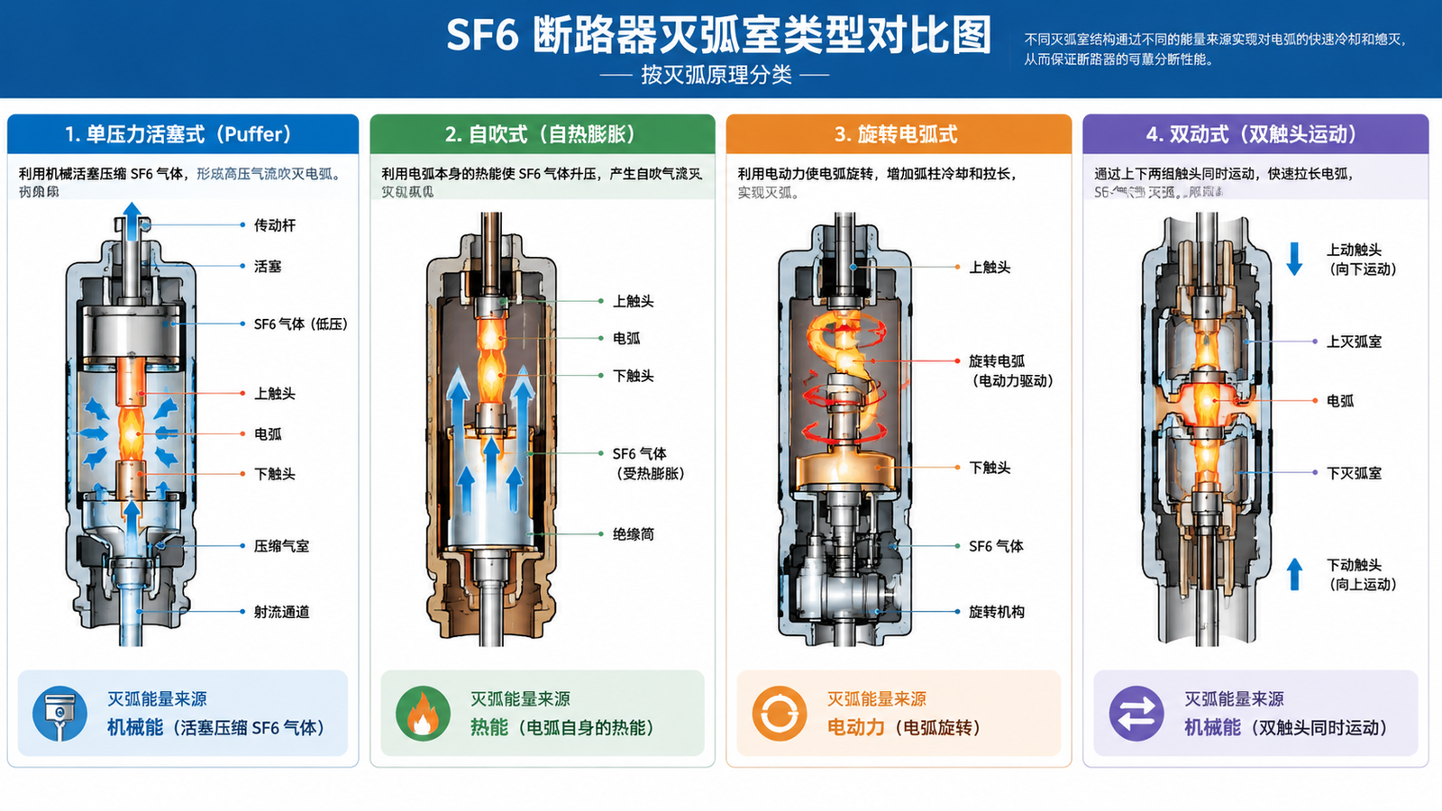
Every type of SF6 circuit breaker solves the same problem — interrupting fault current without damaging the network — but they do it with very different hardware. The two classifications that matter most when you specify equipment are the arc-quenching principle (puffer, self-blast, rotating arc, double motion) and the enclosure construction (live tank, dead tank, grounded tank). Get those two decisions right and the rest of the specification usually falls into place.
This guide explains each type in plain engineering terms, compares them in tables you can reuse in a tender document, and finishes with a practical selection path for 40.5 kV through 252 kV substation projects.
SF6 breakers are not classified by brand or by voltage alone. They are classified in two independent dimensions:
A single breaker therefore has two labels at once. A 126 kV outdoor unit might be described as a “single-pressure puffer, live tank” breaker, while a 252 kV North American substation unit is typically a “self-blast, dead tank” breaker. When someone asks you what type of SF6 breaker you need, the honest answer is a pair of terms, not one.
The interrupter has one job: cool the arc below the temperature at which it can sustain itself, and do it fast enough that the dielectric strength of the gap recovers before the transient recovery voltage arrives. The designs below solve that in different ways.
The oldest commercial approach keeps SF6 at two pressures: a high-pressure reservoir (roughly 1.5 MPa) and a low-pressure system (roughly 0.3 MPa). Opening the breaker releases high-pressure gas through a nozzle across the arc gap, and the exhaust is collected, filtered, recompressed, and returned to the high-pressure side.
It works, but it needs a compressor, heaters to stop the gas liquefying in cold weather, and a much heavier gas system. Double-pressure breakers were largely abandoned during the 1970s in favour of single-pressure designs, and you will only meet them today in legacy installations.
The puffer design is the industry workhorse. The whole interrupter operates at one pressure — commonly around 0.5 MPa for 40.5 kV class equipment. A piston mechanically coupled to the moving contact compresses SF6 in a cylinder as the contacts part, and the compressed gas is driven through an insulating nozzle directly into the arc.
Because the blast pressure is generated mechanically, puffer breakers interrupt consistently across the full current range, from a few hundred amps of load current to full short-circuit current. The trade-off is energy: the operating mechanism has to supply both the contact travel and the gas compression, which means heavier springs, higher operating forces, and more mechanical stress over the breaker’s life.
The self-blast design, also called auto-expansion or thermal expansion, uses the arc’s own energy as the compression source. The arc is struck inside a small enclosed expansion volume; the heat raises the pressure sharply; that pressure then drives the gas back through the nozzle to extinguish the very arc that created it.
The efficiency gain is substantial — published comparisons put the mechanism energy reduction at roughly 50% versus a pure puffer at high currents — which means a lighter mechanism, less wear, and lower maintenance burden.
The catch is current dependence. At high fault currents the arc supplies plenty of energy and self-blast works beautifully. At low currents the arc is weak, pressure build-up is modest, and interruption becomes marginal. Practical self-blast interrupters therefore combine a smaller puffer assist for low-current duties with the thermal expansion chamber for high-current duties. This hybrid arrangement is what most modern HV interrupters actually use, even when they are marketed as “self-blast”.
Instead of blowing gas along the arc, the rotating arc design uses the magnetic field generated by the arc current itself to drive the arc root rapidly around an annular electrode. The arc is stretched and constantly moved into cool, un-ionised gas, so it loses heat by conduction and convection until it can no longer sustain.
Rotating arc interrupters have fewer moving parts and lower mechanical energy requirements, which suits medium-voltage duties. They are less common in the 126 kV and above range, where puffer and self-blast designs dominate.
Double-motion interrupters move both contacts apart instead of holding one stationary. For the same contact gap, each contact only travels half the distance, so the mechanism needs less energy and the breaker responds faster. It is often combined with self-blast rather than used on its own, and it is one of the main levers manufacturers use to shrink mechanism size at higher voltages.
| Type | Blast Energy Source | Interruption Across Current Range | Mechanism Energy | Typical Use |
|---|---|---|---|---|
| Double pressure | Stored high-pressure gas | Good, but dependent on compressor | Low at the interrupter, high in the gas system | Legacy installations only |
| Single-pressure puffer | Mechanical piston | Consistent at all currents | High | Widest range, 13.6 kV to 760 kV class |
| Self-blast / thermal expansion | Arc heat plus puffer assist | Excellent at high current, assisted at low current | Roughly half of a pure puffer | HV and EHV transmission breakers |
| Rotating arc | Electrodynamic arc rotation | Good at medium voltage | Low | MV switchgear and compact units |
| Double motion | Combined with puffer or self-blast | Follows the paired principle | Lower for the same gap | Higher-voltage compact interrupters |
Construction decides where you can install the breaker, how much gas it holds, how you mount current transformers, and how it behaves in an earthquake. The construction of an SF6 circuit breaker is therefore a layout decision as much as an electrical one.
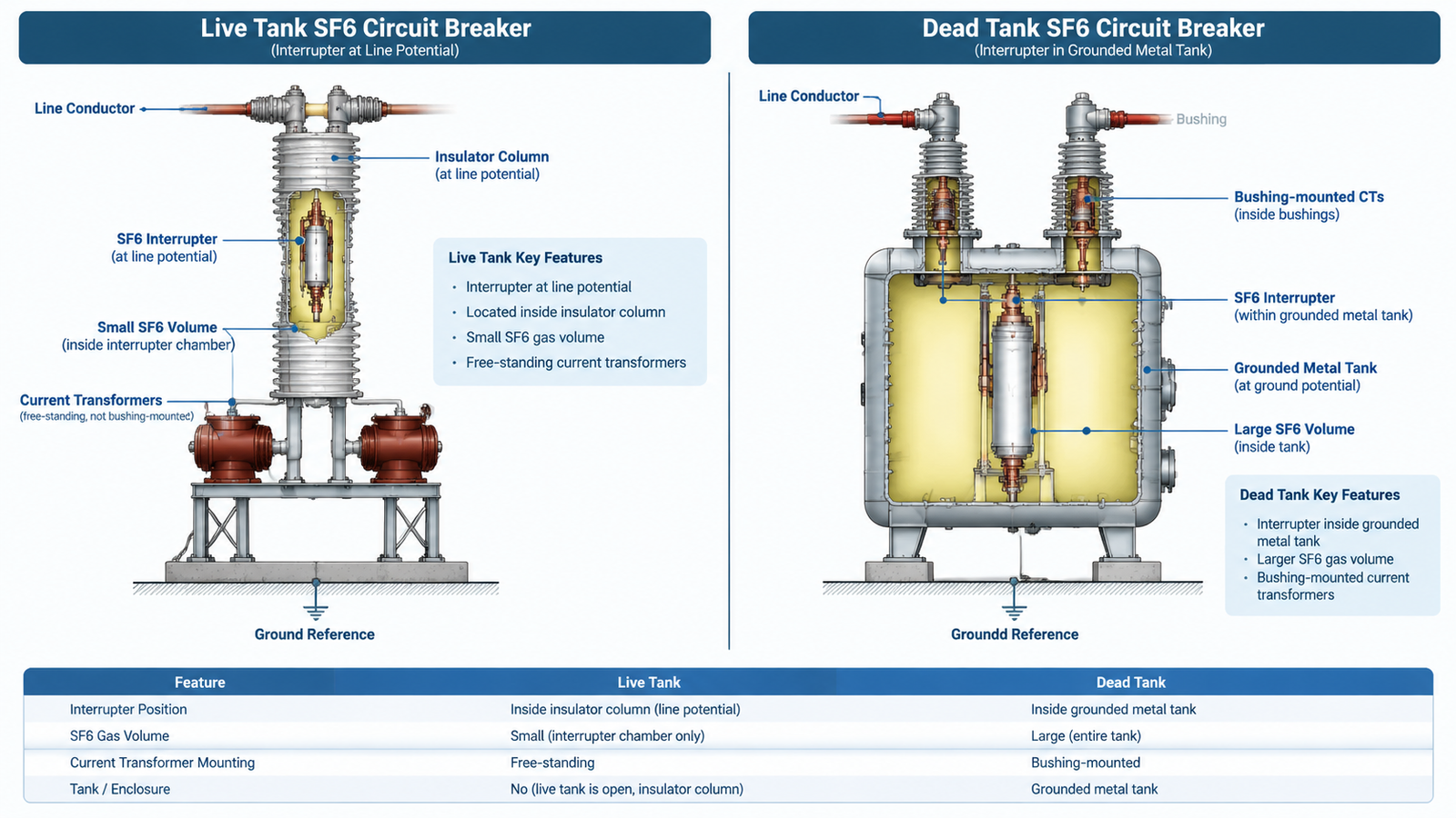
In a live tank breaker the interrupter chamber sits at line potential, mounted on top of a porcelain or composite insulator column that provides the line-to-ground insulation. The interrupting chamber and the support column grow taller as the voltage class rises.
Live tank construction is the dominant choice in Asia, Europe, and most of the world for air-insulated substations. The LW8-40.5 lightning impulse withstand outdoor breaker is a typical example: a three-pole, medium-mounted outdoor unit with a spring mechanism, a 95 kV power frequency withstand rating, and a rated gas pressure of 0.5 MPa.
In a dead tank breaker the interrupter is housed inside a metal tank bonded to earth. The SF6 inside the tank insulates the live contact assembly from the enclosure, and SF6-filled bushings carry the conductors out to the line terminals.
Dead tank designs are the North American convention and are also the natural fit for gas-insulated substations, where the tank integrates directly with SF6 busbar.
The grounded tank design puts a live tank interrupter inside a dead tank enclosure, so part of the assembly operates at line potential and part at earth potential. It is a compromise that appears mainly where utilities want dead tank installation convenience with an existing live tank interrupter design.
| Parameter | Live Tank | Dead Tank |
|---|---|---|
| Interrupter potential | Line potential, inside an insulator | Inside a grounded metal tank |
| SF6 volume | Low — interrupter chamber only | High — chamber plus tank insulation |
| Current transformers | Free-standing units required | Mounted on bushings |
| Internal earth fault risk | Not applicable | Present; protected by bushing CTs |
| Seismic performance | Column height limits performance | Preferred in seismic zones |
| Typical regional preference | Asia, Europe, most AIS projects | North America, GIS integration |
| Maintenance access | Work at height on the column | Work at ground level |
Whatever the label, every SF6 interrupter contains the same functional parts. What changes between types is how they are arranged and driven.
The gas itself does not degrade in a healthy breaker — the properties that make SF6 useful in circuit breakers are stable, which is why pressure and moisture monitoring, not gas replacement, is the routine maintenance task. What wears is the mechanism and the arcing contacts.
Work through these four questions in order. Each one narrows the field quickly.
For 40.5 kV outdoor distribution duties, a live tank single-pressure breaker with a spring mechanism is usually the lowest total-cost answer. Units such as the LW8-40.5 2000A breaker with 95 kV power frequency insulation and the 3000-operation mechanical life variant are built for exactly that duty, with a 0.5 MPa rated gas pressure and a 0.47 MPa alarm threshold that gives operators early warning before performance degrades.
Where higher mechanical endurance or a different gas-pressure regime is required, the 0.5 MPa rated gas pressure model covers the same 40.5 kV class with a specification tuned to a defined pressure envelope. Confirming the exact interrupter type, mechanism type, and CT arrangement with the manufacturer before the tender closes is the cheapest form of risk control on this equipment.
There are two real questions behind “types of SF6 circuit breakers”: how the arc is quenched, and where the interrupter sits. Puffer and self-blast dominate HV and EHV interruption; rotating arc and double-motion designs solve specific problems at the edges. Live tank construction keeps gas volume low and suits air-insulated substations worldwide, while dead tank construction brings bushing-mounted CTs and better seismic behaviour at the cost of more gas.
Match those two decisions to your voltage class, installation environment, fault level, and protection scheme, and the specification writes itself. If you are working through a 40.5 kV to 252 kV project and want the interrupter type and mechanism confirmed against your duty, send the ratings and we will check the configuration before you commit.
SF6 breakers are classified two ways. By arc-quenching principle: double-pressure (obsolete), single-pressure puffer, self-blast or thermal expansion, rotating arc, and double motion. By enclosure construction: live tank, dead tank, and grounded tank.
A puffer breaker uses a mechanical piston to compress SF6 and blast the arc, so it interrupts consistently at any current but needs a heavier mechanism. A self-blast breaker uses the arc’s own heat to pressurise the gas, cutting mechanism energy by roughly half, and normally pairs that with a small puffer assist for low-current interruption.
In a live tank breaker the interrupter sits at line potential inside an insulator column, so it holds a small gas volume and needs free-standing current transformers. In a dead tank breaker the interrupter sits inside a grounded metal tank, which allows bushing-mounted CTs and better seismic performance but requires more SF6.
For 40.5 kV outdoor distribution and small substations, a live tank single-pressure puffer breaker with a spring operating mechanism is the usual choice. It keeps the gas system small, suits column mounting, and covers typical fault levels without the extra cost of dead tank construction.
No. Double-pressure SF6 breakers required a compressor, heaters, and a large two-pressure gas system, and were superseded by single-pressure designs during the 1970s. You will only find them in legacy installations.
Ask directly for the interrupter principle, the mechanism type, and the gas pressure regime, and request them in writing in the technical data sheet. The breaker’s type test certificate and rating plate will also state the standard and rated pressures, which lets you cross-check the claim.