LW36-126 Explained: 3150 A, 40 kA and 40 kA/3 s in Practical Terms
What the LW36-126 model number covers, what it does not, and how to pick between the six variants and specify the items the model omits.
Read More
The rating plate says 40 kA. The datasheet says 126 kV, 3150 A, 3 s. None of it explains why one breaker weighs 1,200 kg and another of the same rating weighs 1,800 kg, why one needs a 2 kW spring charging motor and the other gets away with 800 W, or why one is rated for 10,000 operations and the other for 2,000. All of those answers live inside the SF6 circuit breaker interrupter — the sealed assembly where the arc is drawn, choked, cooled and extinguished within a few milliseconds.
This article takes the interrupter apart conceptually: the four jobs it has to do, the two ways of finding the energy to do them, what nozzle ablation actually contributes, why double-motion contacts change the economics of the whole breaker, and how the arc energy balance in the last hundred microseconds decides whether the unit re-ignites or clears. It applies to single-break interrupters across the SF6 circuit breaker range.
An interrupter has to do four things in sequence, and it has about five milliseconds at 50 Hz to do all of them.
Every design decision in an interrupter is a trade against one of those four. The differences between puffer and self-blast designs, and between single-motion and double-motion contacts, all come down to where the energy for step two is found.
The gas flow across the arc has to be driven by a pressure difference, and there are only two ways to create one.
A puffer interrupter uses the operating mechanism to compress gas. As the contacts part, a piston moving in a cylinder squeezes the SF6 in a compression volume, and that compressed gas is ducted through the nozzle across the arc. The pressure is available immediately, at any current, and it is entirely predictable.
The cost is mechanical. The compression force is proportional to the cylinder area and the pressure ratio required, and it is highest at the end of the stroke when the contacts are fully apart. A puffer interrupter therefore demands a large operating mechanism, a heavy spring or a hydraulic drive, and a strong mechanical structure to carry the reaction. That is where the extra weight and the bigger charging motor come from.
A self-blast — also called thermal expansion — interrupter finds the energy in the arc itself. The arc is confined in a small expansion volume behind the nozzle throat. Its thermal energy heats the gas in that volume, raising the pressure without any mechanical work from the mechanism. At current zero, that stored pressure drives the hot gas back out through the throat and across the arc, extinguishing it.
The advantage is dramatic: the mechanism only has to move the contacts, not compress gas, so the operating energy falls by a large factor and the whole drive train can be smaller, lighter and cheaper. This is why self-blast interrupters dominate modern 72.5 kV to 252 kV single-break designs.
The disadvantage is a minimum current. Below a certain fraction of rated breaking current — typically somewhere around 20 to 30% — the arc does not have enough energy to build the required pressure. The interrupter then has no blast at all and will fail to interrupt. The standard solution is a hybrid: a small auxiliary puffer volume that handles the low-current range, with the self-blast mechanism taking over above the crossover. Some designs add a “double volume” arrangement or a check valve so the same hardware covers both regimes.
| Feature | Puffer | Self-blast (thermal expansion) |
|---|---|---|
| Energy source | Operating mechanism compresses gas | Arc thermal energy pressurises expansion volume |
| Operating energy | High, proportional to cylinder area | Low, contacts only |
| Mechanism size | Large; heavy spring or hydraulic | Compact; lighter spring |
| Performance at low current | Full, at any current | Requires auxiliary puffer below ~20–30% of rating |
| Performance at high current | Good, but compression must be sized for it | Excellent; more current means more blast pressure |
| Typical application | Older designs, very high currents, generator breakers | 72.5 kV – 252 kV single-break transmission breakers |
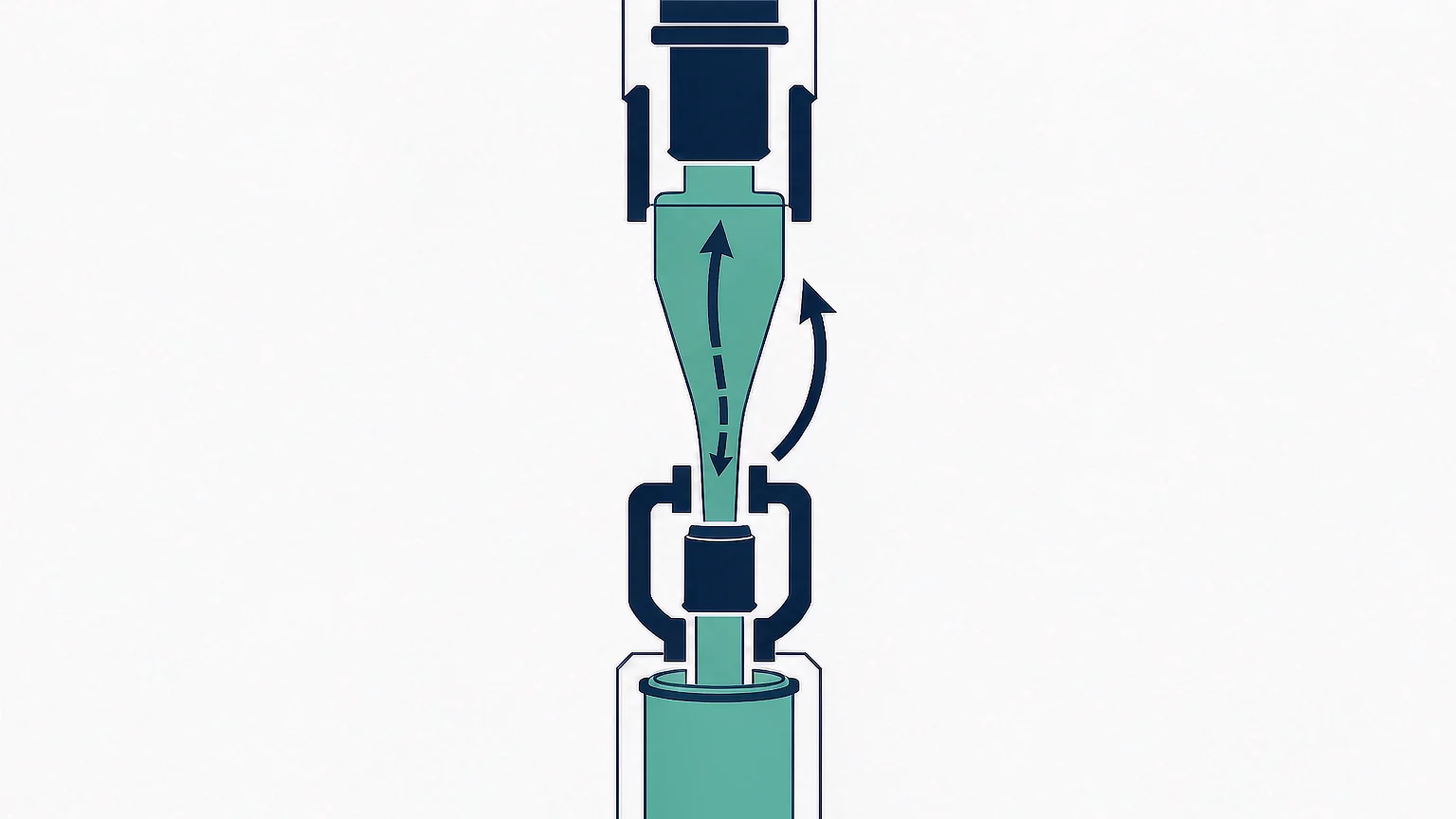
The nozzle is the narrow throat the arc burns through, and it is almost always made of PTFE. What happens to it during an interruption is one of the more elegant pieces of engineering in high-voltage switchgear.
PTFE does not melt away passively. Under the arc it ablates — it vaporises into fluorocarbon fragments, and those fragments are themselves strongly electronegative. They attach electrons, they cool the arc column by dissociating and recombining, and they add mass to the gas flow. In a self-blast design they also contribute directly to the pressure rise in the expansion volume, because the ablated vapour is a significant fraction of the total gas mass in that small volume at high current.
So the nozzle is not just a passive constriction. It is a consumable that participates in the interruption. That has three consequences worth understanding.
Because the nozzle constricts the arc, the arc voltage is not constant. At high current the arc is thermally clogged in the throat: it is squeezed into a narrow channel, its resistance rises, and the arc voltage climbs steeply. In SF6 at 40 kA the arc voltage per break typically sits in the range of 300 to 600 V and rises through the interruption.
That number is small compared with air-blast or oil breakers, and it is the reason SF6 interrupters are compact. Low arc voltage means low arc energy for the same current and duration, which means less gas to heat, less pressure to contain and less material to ablate. The whole compactness of modern HV switchgear follows from that one property.
A conventional interrupter holds one contact still and drives the other through the full contact gap. A double-motion interrupter drives both, in opposite directions, so each travels half the distance.
The consequences are larger than they look. The operating energy of a spring mechanism scales roughly with the square of the travel for the accelerating mass, and the energy stored in the spring scales with travel too. Halving the travel per contact roughly halves the required drive energy and, for the same spring, allows either a smaller mechanism or a faster operation. The contact separation speed relative to the arc — which is what actually matters for dielectric recovery — is unchanged or improved, because the relative velocity is the sum of the two contact velocities.
The mechanical benefits follow: less reaction force into the support structure, smaller foundation loads, lighter porcelain or composite columns, less fatigue on the flexible shunts, and a smaller charging motor. The operating mechanism comparison covers how that translates into spring, pneumatic and hydraulic choices.
The cost is mechanical complexity in the interrupter: a second moving assembly, a second set of guides, and a linkage that has to keep both contacts aligned to a fraction of a millimetre through 10,000 operations. That is why double motion appears mainly where the benefit is largest — 126 kV and 252 kV single-break units, where the alternative is a much heavier mechanism or a two-break arrangement with grading capacitors.
The last hundred microseconds decide everything. Two regimes matter, and they are usually drawn as regions on an arc energy diagram.
At high instantaneous current, the arc fills the nozzle throat and the gas flow is blocked by the arc’s own pressure. Energy accumulates in the expansion volume faster than it can escape. This is the storage phase: the interrupter is charging itself for the interruption that happens at current zero.
The design question here is containment. The expansion volume has to hold the pressure without distorting, and the nozzle has to survive the thermal flux without disintegrating. Both are dimensioned by the highest current the breaker is rated to break.
As the current falls toward zero, the arc stops being thermally clogged. The stored pressure now drives gas through the throat, sweeping the hot column out of the contact gap. The arc becomes diffuse and its resistance rises sharply.
What follows is the thermal recovery period — roughly the first 100 to 500 µs after current zero — during which the gas is still hot enough to be weakly conductive. If the transient recovery voltage rises faster than the gas can recover its dielectric strength, a small post-arc current flows, the gas heats again, and the breaker re-ignites. This is a thermal failure, and it is the dominant failure mode for a breaker interrupting close to its rating.
If the gas survives the thermal period, the remaining question is dielectric: whether the contact gap, now filled with cool gas, can withstand the peak of the recovery voltage. That is a dielectric failure, and it usually happens later and at a higher voltage.
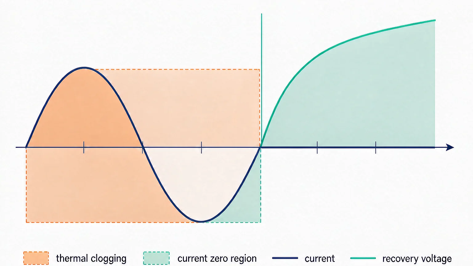
| Phase | Timing | What is happening | Failure mode if it goes wrong |
|---|---|---|---|
| Thermal clogging | During high current | Arc blocks the throat; pressure builds in the expansion volume | Nozzle rupture, over-pressure, insufficient stored energy |
| Blast phase | Approaching current zero | Stored pressure drives gas across the arc | Weak blast; hot gas remains in the gap |
| Thermal period | 0 – 500 µs after zero | Residual hot gas conducts briefly | Thermal re-ignition under fast RRRV |
| Dielectric period | 0.5 – 50 ms after zero | Cool gas must hold the recovery voltage | Dielectric breakdown at TRV peak |
Interrupter architecture is not a detail you can leave to the supplier, because it determines four things you will live with for twenty years.
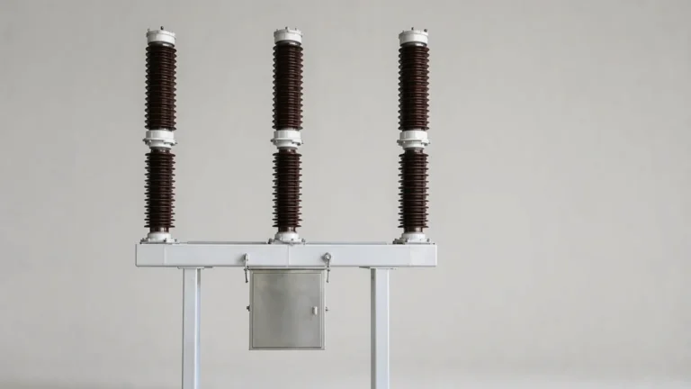
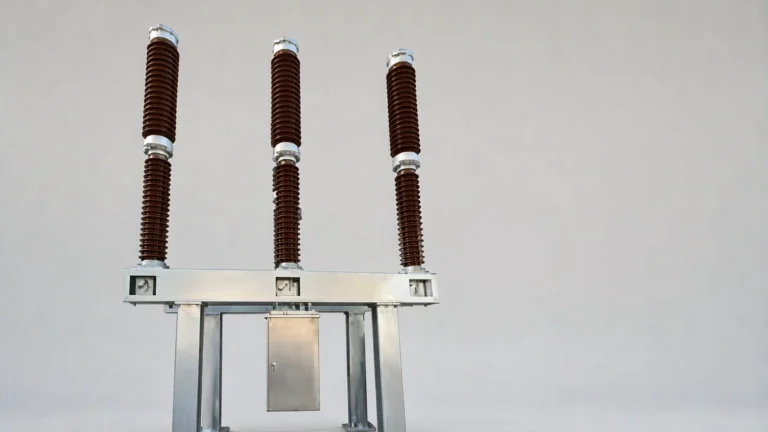
Two products illustrate how the same architecture scales. The LW36-126 with 40 kA breaking capacity is a single-break 126 kV design where the interrupter has to deliver 40 kA with a compact spring drive — the case where double motion and self-blast pay for themselves. The LW9-72.5 with 4000 A and high breaking capacity carries the same interrupter family at a lower voltage but a much higher continuous current, which shifts the design problem from arc energy to heat rejection from the main contacts.
At 72.5 kV with a high lightning impulse requirement, the LW9-72.5 with 350 kV lightning impulse withstand shows the other constraint: once the external insulation is pushed up, the interrupter and the porcelain have to be designed together, because the contact gap that gives good interruption is not necessarily the gap that gives good external withstand.
Vacuum interrupters also extinguish arcs, and below about 24 kV they do it better and more cheaply. The reason SF6 still dominates above 72.5 kV is exactly the arc energy balance described above: vacuum interruption depends on the arc staying diffuse and on the contact material condensing the metal vapour within microseconds, and that mechanism does not scale to 40 kA at 126 kV in a single gap. SF6’s electronegativity and its thermal properties give a dielectric recovery that scales with pressure and gap, which is what makes a single-break 252 kV interrupter possible. The trade-offs are set out in SF6 versus vacuum.
The interrupter is where a breaker’s ratings are actually earned. The puffer and self-blast choice decides how much mechanism you have to buy; nozzle ablation decides how the interruption is completed and how the unit wears; double motion decides how much drive energy the whole design needs; and the arc energy balance in the last few hundred microseconds decides whether it clears or re-ignites.
When comparing two breakers at the same nominal rating, ask which architecture each uses, how the low-current range is covered, whether the nozzle is replaceable, and what the operating energy is. Those four answers explain most of the price and weight difference, and they predict the maintenance bill far better than the headline kA figure. For the arc-quenching physics behind all of this, see why SF6 gas is used in circuit breakers; for how these architectures are classified commercially, see SF6 circuit breaker types and the wider article library.
The sealed assembly containing the arcing contacts, the nozzle and the expansion volume, where the arc is drawn and extinguished. It is the part of the breaker that determines its breaking capacity and electrical endurance, as distinct from the mechanism that drives it.
A puffer uses the operating mechanism to compress gas for the blast; a self-blast uses the arc’s own thermal energy to pressurise a small expansion volume. Self-blast needs far less operating energy but requires an auxiliary puffer to cover the low-current range.
Because PTFE ablates into electronegative fluorocarbon fragments that cool the arc and add to the blast pressure, while surviving the thermal flux long enough to do it. It is a consumable that participates in the interruption rather than a passive constriction.
Both contacts move apart instead of one, so each travels half the distance for the same gap. This roughly halves the required operating energy, allowing a smaller mechanism, lighter structure and lower foundation loads.
Usually a thermal failure: the gas in the contact gap is still hot and weakly conductive in the first few hundred microseconds, and a fast-rising recovery voltage drives a post-arc current that reheats it. This is why short-line faults, with their very high rate of rise, are the most severe duty.
Through nozzle wear and contact erosion. A design with a replaceable nozzle can be refurbished in the field; a sealed-for-life unit must be replaced as a whole. Lower operating energy also reduces mechanism wear, which is the largest driver of mechanical maintenance cost.