Oil Immersed Transformer Working Principle, Types & Selection Guide
Published: Author: Lisa
An oil immersed transformer is the workhorse of medium- and high-voltage power distribution — the unit you find in substations, industrial plants, and renewable energy projects where cooling capacity, overload margin, and long service life matter more than a compact footprint. Most specification mistakes do not start with the brand or the price. They start earlier, when a buyer orders a transformer without understanding how it works, what its components do, or how the cooling class affects loading. This guide explains what an oil-filled transformer is, how it operates, its main components and types, and the judgment you need before sending an RFQ.
What Is an Oil Immersed Transformer?
An oil immersed transformer is a transformer whose core and windings are fully submerged in insulating oil inside a sealed tank. The oil is not just a coolant. It is also the primary electrical insulation between live parts, and it shields the core and winding materials from moisture and oxidation. Because oil has a far higher dielectric strength and thermal conductivity than air, an oil-filled design can reach voltage and capacity levels that air-cooled dry-type units cannot match economically.
In practice, that matters because thermal behavior is not a design detail — it controls how much load the transformer can carry, how fast the insulation ages, and how many decades the unit lasts. A buyer who ignores oil performance is buying a nameplate rating, not a real operating asset.
The Role of Insulating Oil
Transformer oil performs three jobs at once: it insulates, it cools, and it protects. It provides high dielectric strength between the high-voltage winding, the low-voltage winding, and the grounded tank. It carries heat from the windings and core to the tank walls and radiators, where it dissipates into the air. And it isolates the active materials from oxygen and humidity, which are the main drivers of insulation aging. When the oil degrades — through moisture, oxidation, or contamination — all three functions weaken at the same time, which is why oil condition, not the nameplate, is usually the first sign of transformer health.
How an Oil Immersed Transformer Works
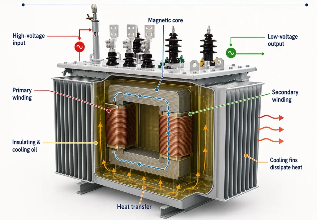
The operating principle is electromagnetic induction. Alternating current in the primary winding creates a magnetic flux in the laminated steel core. That flux passes through the secondary winding and induces an output voltage. The voltage ratio follows the turns ratio: V₂ / V₁ = N₂ / N₁, so a transformer with more secondary turns steps voltage up, and one with fewer secondary turns steps it down.
While energy transfers between windings, copper losses in the conductors and core losses in the steel generate heat. The surrounding oil absorbs that heat and circulates — naturally or with pumps — to the radiators, where it cools and returns to the tank. This oil cooling cycle is what allows the unit to run continuously at high load without overheating the insulation.
Main Components and What Each One Does
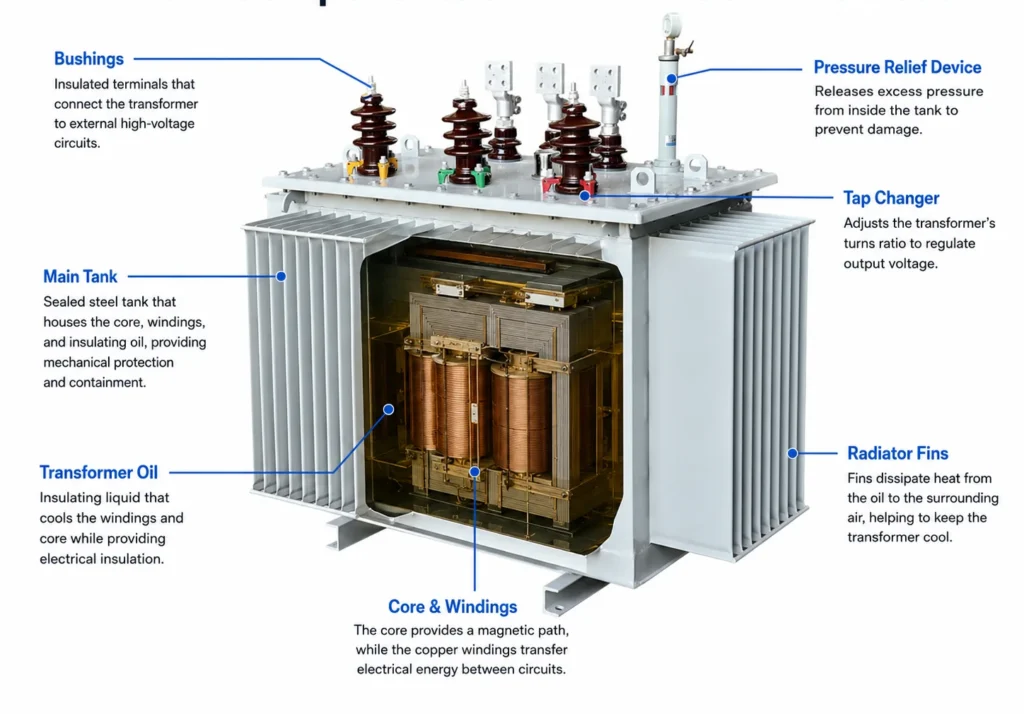
The unit is built from a small number of functional groups. Knowing what each one does helps you read a datasheet and a maintenance report instead of treating the transformer as a black box.
Component
Function
Why it matters to the buyer
Core (laminated silicon steel)
Carries the magnetic flux between windings
Core material and loss grade set no-load loss, which you pay for every hour the transformer is energized
Windings (copper or aluminum)
Carry current and transfer energy between circuits
Conductor material and cross-section set load loss and short-circuit strength
Insulating oil
Cools, insulates, and protects active parts
Oil type and condition decide dielectric strength and maintenance cost over the unit’s life
Main tank
Holds the core, windings, and oil; provides mechanical protection
Tank design affects sealing, outdoor rating, and oil-leak risk
Conservator (oil expansion tank)
Allows oil to expand and contract with temperature
Present on free-breathing units; sealed designs use a different expansion method
Breather (silica gel)
Dries air entering the conservator
Saturated silica gel lets moisture into the oil — a common, preventable failure cause
Radiators / cooling fins
Release heat from the oil to the air
Surface area and fan staging set the cooling class and overload margin
Buchholz relay
Detects gas buildup and oil surge from internal faults
A key protection device — confirm it is included and tested on any unit you buy
Tap changer
Adjusts the turns ratio to regulate output voltage
Off-circuit vs on-load tap changer changes price and the voltage-regulation you can achieve
Bushings
Brings high-voltage conductors through the grounded tank
Bushing rating and creepage must match site pollution and voltage level
Cooling Methods: ONAN, ONAF, OFAF, and OFWF
The cooling class defines how oil and air move through the transformer, and it directly limits how much power the unit can handle before insulation temperature becomes unsafe.
Cooling class
How it works
Typical use
ONAN (Oil Natural Air Natural)
Oil circulates by natural convection; air cools the radiators naturally
Small to medium distribution transformers — simplest and lowest maintenance
ONAF (Oil Natural Air Forced)
Oil still circulates naturally, but fans force air over the radiators
Medium to large units; fans switch on at a set temperature to add overload capacity
OFAF (Oil Forced Air Forced)
Oil pumps move the oil and fans move the air
Large power transformers where forced circulation raises cooling efficiency
OFWF (Oil Forced Water Forced)
Oil pumps plus a water heat exchanger replace air cooling
Large plants, underground substations, or sites where water cooling is available
The practical rule: more forced cooling buys you more capacity in the same physical size, but it adds fans, pumps, controls, and maintenance points. Match the cooling class to the real load profile, not to a peak you will never see.
Common Types of Oil Immersed Transformers
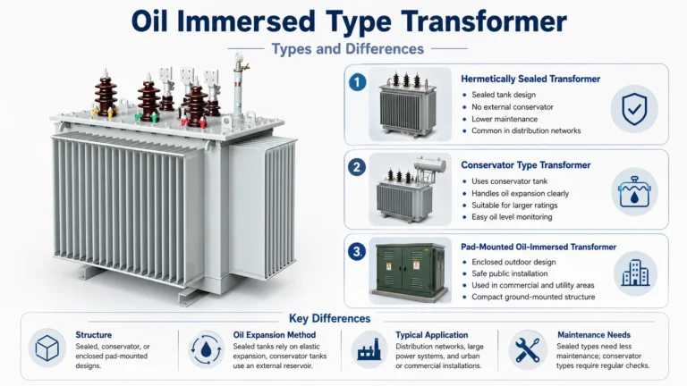
These transformers are grouped two ways. By structure, the main split is between sealed-type units, where the tank is closed and oil expansion is absorbed internally, and conservator-type units, which use an external expansion tank and a breather. Sealed designs reduce oil contact with air and suit smaller distribution ratings; conservator designs are standard for larger power transformers because they handle larger oil volume changes.
By application, the families that matter to most buyers are:
Distribution transformers — step medium voltage (commonly 10kV or 35kV) down to 400V for industrial parks, commercial buildings, and residential networks.
Power transformers — larger units in substations that move voltage between transmission and distribution levels.
Step-up transformers — raise generator output voltage for grid connection, typical in power plants and renewable sites.
Special-purpose units — rectifier, furnace, and traction transformers built for a specific industrial duty.
Where the load is lighter or the site needs single-phase distribution, an oil-type single-phase transformer is often a better fit than a three-phase unit, because it simplifies pole-mounted and rural distribution.
Where Oil Immersed Transformers Are Used
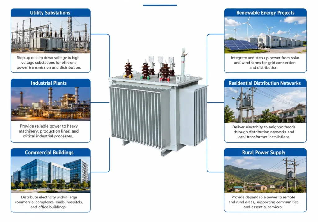
These units appear wherever medium or high voltage must be converted and the site can accommodate an oil-filled design. The strongest cases are outdoor substations, where capacity range and thermal margin matter; industrial plants with continuous heavy loads such as steel, cement, and petrochemical sites; renewable projects, where step-up transformers connect wind and solar generation to the grid; and infrastructure like railways, data centers, and large commercial complexes that need a reliable main transformer.
For medium-voltage distribution specifically, the 10kV oil immersed transformer selection guide breaks down how to match voltage ratio, loss class, and installation environment. If your project is moving from “what is it” to “which one do I order,” Hairui Electric’s oil immersed transformer range covers sealed and conservator designs across common distribution ratings.
Oil Immersed vs Dry Type Transformer
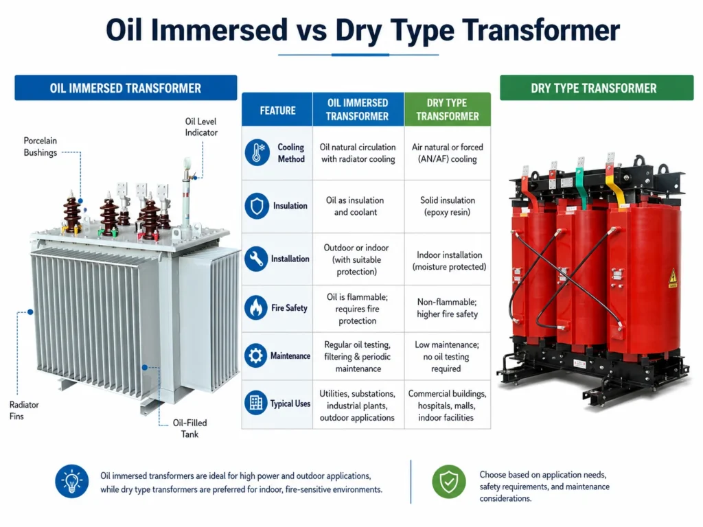
The comparison that decides most projects is not between two oil models — it is between oil immersed and dry type. The core trade-off is cooling and cost against fire safety and placement flexibility.
Factor
Oil-filled transformer
Dry type transformer
Cooling and insulation
Insulating oil
Air and solid insulation
Capacity and voltage range
Wide, up to hundreds of MVA and very high voltage
Usually smaller, medium voltage
Typical placement
Outdoor substations, dedicated electrical rooms
Indoor, close to occupied space
Fire consideration
Oil is combustible; fire-protection measures required
Oil-free, lower fire load
Cost at comparable rating
Usually lower
Usually higher
Maintenance
Oil testing and filtration needed
Minimal oil-related maintenance
Choose the oil-filled option when the project is substation-based, outdoor, capacity-sensitive, or driven by total cost of ownership over many years. Choose dry type when the unit sits inside an occupied building or where fire rules dominate. For the full point-by-point breakdown, see the comparison of dry type and oil immersed transformer differences.
Key Specifications to Check Before Buying
A serious RFQ confirms more than kVA and price. The parameters below decide whether the transformer fits the system and whether the quoted price is honest.
Parameter
Why it matters
What to confirm
Rated capacity (kVA)
Sets the load the unit can carry without sustained overload
Actual load profile and future expansion, not just today’s peak
Voltage ratio
Must match primary supply and secondary distribution level
Primary, secondary, frequency (50/60 Hz), and tap range
No-load loss
Present whenever the transformer is energized
Whether long operating hours justify a low-loss grade
Load loss
Rises with current and affects running efficiency
Expected loading range, not only full-load rating
Cooling class
Limits continuous and overload capacity
ONAN/ONAF/OFAF match to ambient temperature and duty
Insulation level and standard
Defines dielectric strength and test acceptance
Applicable standard (e.g. IEC 60076) and routine tests included
A well-maintained unit commonly runs 25 to 40 years, and large power units can exceed that. The life limit is almost always the paper insulation, and paper aging is driven by heat, moisture, and oxygen — all of which the oil condition reflects.
The tests that matter are Dissolved Gas Analysis (DGA), which detects internal faults by reading gases dissolved in the oil, and the BDV (breakdown voltage) test, which measures the oil’s dielectric strength. BDV is typically checked every 6 to 12 months; DGA frequency rises with unit size and criticality. Day-to-day, monitor top-oil temperature — keep it below about 85°C to avoid accelerated aging — and replace breather silica gel before it saturates. These routine checks are covered in more depth in the guide to selecting, connecting, and buying an oil immersed transformer.
FAQ
What is an oil immersed transformer used for?
It is used to convert voltage in medium- and high-voltage power systems — stepping distribution voltage down to 400V for industrial and commercial use, or stepping generator voltage up for grid connection. It is the standard choice for outdoor substations, industrial plants, and renewable energy projects.
How long does an oil immersed transformer last?
With proper maintenance, a distribution unit typically lasts 25 to 35 years and a power transformer 30 to 40 years or more. The limiting factor is the paper insulation, which ages faster when the oil runs hot, wet, or contaminated.
What oil is used in an oil-filled transformer?
Most units use highly refined mineral oil. Projects with stricter environmental or fire rules use natural ester or synthetic ester fluids, which biodegrade more readily and have a higher flash point.
What is the difference between ONAN and ONAF cooling?
ONAN (Oil Natural Air Natural) relies on natural oil and air circulation and suits smaller distribution units. ONAF (Oil Natural Air Forced) adds fans to force air over the radiators, which raises the continuous and overload capacity of a larger unit without enlarging the tank.
Is an oil-filled transformer safe for indoor installation?
It can be installed indoors, but only in a dedicated, fire-rated electrical room with oil containment, ventilation, and the protection devices the local code requires. For occupied indoor space, a dry type transformer is usually the safer choice.
How often should transformer oil be tested?
BDV testing is typically done every 6 to 12 months, and DGA at least annually for larger or critical units. Test more often after a fault, after heavy overload, or when the unit approaches end of life.
Choosing the Right Oil Immersed Transformer
This transformer is the right choice when the project needs high capacity, strong cooling, and a long service life in an outdoor or dedicated-room installation. The decision logic is straightforward: confirm the voltage ratio and capacity the load actually needs, pick the cooling class that matches the real duty, weigh no-load and load loss against operating hours, and check that the site can handle oil-filled fire and containment rules. Only after those points are settled does supplier and price become meaningful.
The broader case for oil-filled designs in B2B projects — including total-cost-of-ownership and efficiency arguments — is set out in the overview of advantages of oil immersed transformers for B2B buyers. If you have a specific voltage, load, and installation environment in mind, contact the Hairui Electric team with those details and we will confirm the right type, cooling class, and loss grade for your project.
If you are evaluating oil immersed transformers for a substation, industrial plant, or renewable energy project, the variety of available types can make selection feel complicated. The distinctions are not only about kVA and voltage. They extend to cooling class, tank construction, phase configuration, insulating fluid chemistry, winding material, and the specific duty the transformer […]
At its simplest, an oil immersed transformer (also called an oil filled transformer or oil type transformer) is a static electrical device that transfers energy between circuits through electromagnetic induction, with its active parts fully submerged in insulating oil.
This guide explains how to choose a 10kV oil immersed transformer, compare it with dry type units, evaluate losses, and assess manufacturers for substation and industrial projects.