Oil Immersed Transformer Type Difference Complete Guide
Published: Author: Lisa
If you are evaluating oil immersed transformers for a substation, industrial plant, or renewable energy project, the variety of available types can make selection feel complicated. The distinctions are not only about kVA and voltage. They extend to cooling class, tank construction, phase configuration, insulating fluid chemistry, winding material, and the specific duty the transformer must perform year after year.
This article maps out the main oil immersed transformer types and their key differences so you can match the right configuration to your project requirements. We compare each type across cooling performance, cost, maintenance demands, and application fit, with practical selection guidance along the way.
Classification Dimensions at a Glance
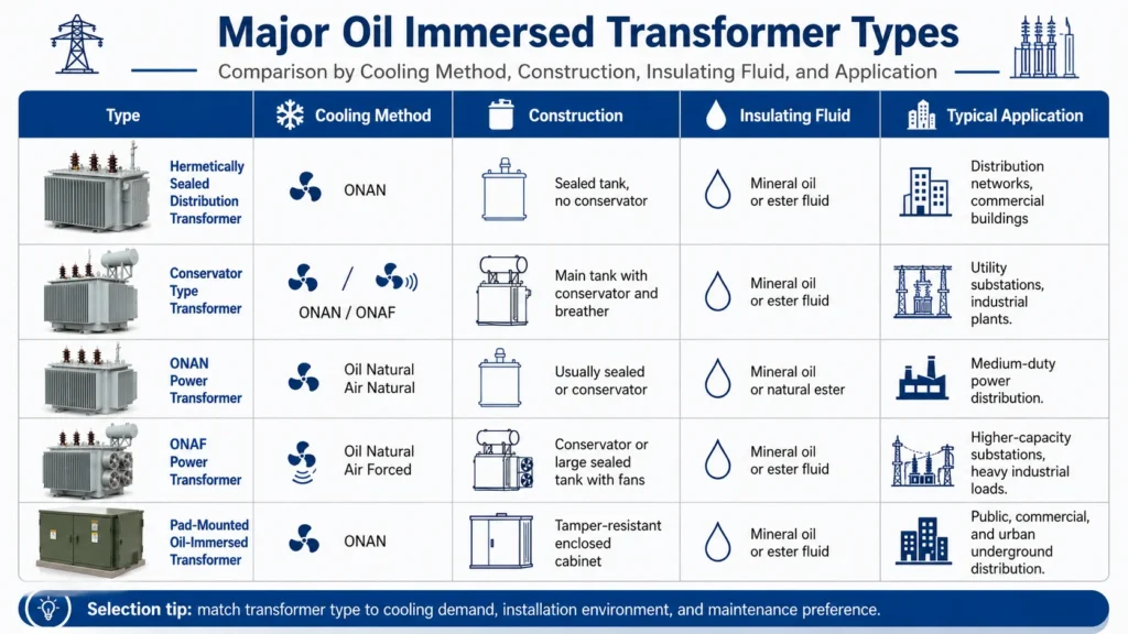
Oil immersed transformers are classified along several independent dimensions. Two units with the same kVA rating can be built very differently depending on the choices made in each category. The table below summarizes the main classification axes and the available options under each.
Classification Dimension
Available Types
What the Choice Affects
Cooling method
ONAN, ONAF, OFAF, OFWF
Load capacity, size, auxiliary power, maintenance
Oil preservation / tank design
Hermetically sealed, conservator-type
Moisture protection, voltage range, service intervals
Phase configuration
Single-phase, three-phase
Application fit, transportability, cost per MVA
Application / function
Distribution, power, step-up, special-purpose
Rating, duty cycle, voltage class, protection features
Insulation design, tank construction, protective devices
None of these choices are purely academic. A hermetically sealed ONAN unit with aluminum windings and mineral oil is a completely different asset from a conservator-type OFAF unit with copper windings and ester fluid, even if both nameplates show the same kVA. The sections that follow explain what distinguishes each type and where each fits best.
Types by Cooling Method: ONAN, ONAF, OFAF, and OFWF
Cooling classification is the first dimension most engineers check because it sets the thermal ceiling of the transformer. The four-letter IEC code describes how the internal fluid (oil) and the external medium (air or water) move through the unit.
How the Four Cooling Classes Compare
Cooling Class
Oil Circulation
Air/Water Circulation
Moving Parts
Typical Capacity Range
ONAN
Natural convection
Natural air
None
Up to ~25 MVA
ONAF
Natural convection
Forced air (fans)
Fans
~10 to ~60 MVA
OFAF
Forced (pumps)
Forced air (fans)
Pumps + fans
~60 to ~500+ MVA
OFWF
Forced (pumps)
Forced water
Pumps + water system
~100+ MVA, specialized
Key Differences in Performance
ONAN is the simplest design. Oil rises by natural convection as it warms, cools at the radiator surfaces, and sinks back down. There are no fans, no pumps, and nothing that needs auxiliary power. This makes ONAN the cheapest to buy and the easiest to maintain, but it also has the lowest cooling efficiency. It suits smaller distribution transformers under about 10 to 25 MVA where continuous load is moderate and the ambient climate is forgiving.
ONAF adds fans that blow air across the radiators when the oil temperature reaches a set threshold. The oil still circulates naturally. This buys roughly 30 to 40 percent more capacity than ONAN in the same tank size without adding oil pumps. Many medium-voltage transformers are built with a dual ONAN/ONAF rating: the base rating is ONAN, and the fan-boosted rating is ONAF. This gives operators built-in overload headroom.
OFAF uses pumps to force oil through the windings and cooling loops, combined with forced-air fans. The active circulation significantly raises heat removal. OFAF units handle large power transformers above about 60 MVA and accept higher continuous loads. The trade-off is higher initial cost, more maintenance points, and auxiliary power consumption for pumps and fans.
OFWF replaces air cooling with a water heat exchanger. It is used mainly in large generating stations, underground substations, or sites where cooling water is plentiful and air cooling is impractical. OFWF offers the highest cooling density but introduces water system complexity and is rarely seen outside heavy industrial or utility environments.
Cooling Type Selection by Project Profile
Project Type
Recommended Cooling
Why
Rural distribution, pole-mounted
ONAN
No auxiliary power, zero fan maintenance, quiet operation
Industrial feeder, medium load
ONAN/ONAF dual rating
Normal load handled passively; fans engage during peaks
Urban substation, space-limited
ONAF or OFAF
Higher capacity in same footprint; fans or pumps compensate
Large power plant, greater than 100 MVA
OFAF
Active cooling needed for continuous high load
Underground or water-cooled site
OFWF
Water cooling where air exchange is limited
Types by Oil Preservation: Hermetically Sealed vs Conservator-Type
The way the transformer tank manages oil expansion and contact with ambient air is a fundamental design split. It determines moisture risk, maintenance frequency, and the voltage class the unit can serve.
Hermetically Sealed Transformers
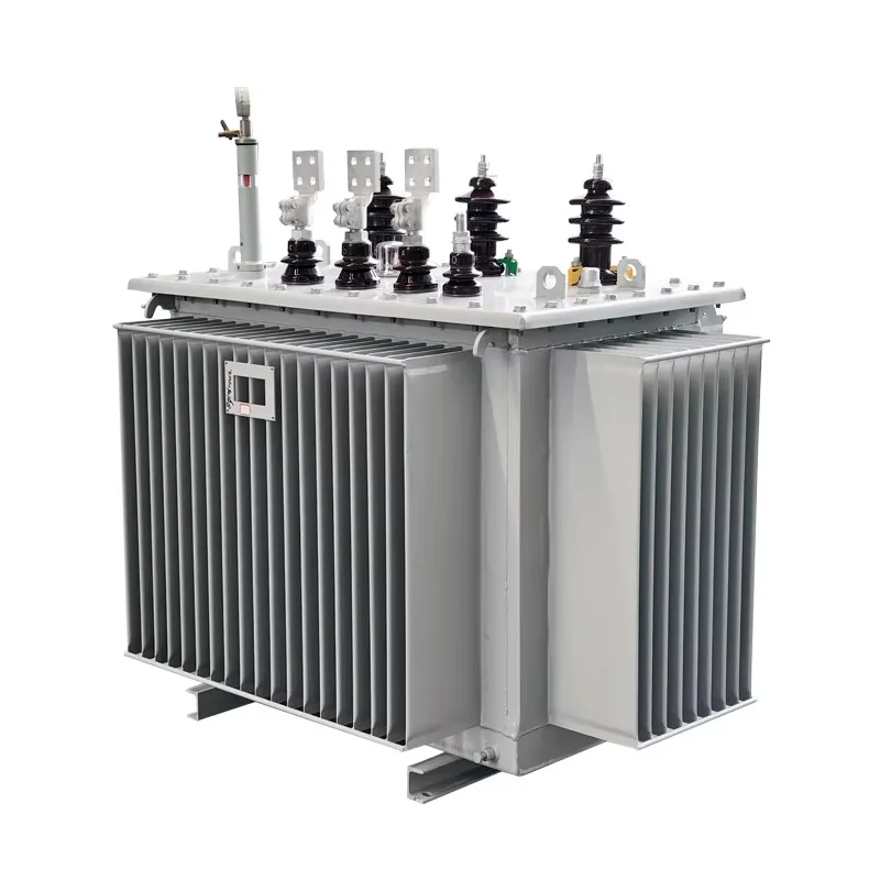
A hermetically sealed transformer has a fully welded tank with no opening to the atmosphere. Oil expansion is absorbed by flexible tank walls, internal gas cushions, or deformable radiators. Because air and moisture never enter the tank during normal operation, oxidation and wetting of the oil are greatly reduced. These units are virtually maintenance-free in terms of oil handling, which is why they are popular for pole-mounted distribution, compact urban substations, and remote renewable sites where regular service visits are difficult.
The limitation is physical. A sealed tank can only accommodate a certain oil volume change before pressure becomes unmanageable. This caps sealed designs at around 36 kV and roughly 5 MVA, though some manufacturers stretch this with nitrogen-cushioned sealed tanks. Above that range, a conservator becomes necessary.
Conservator-Type Transformers
A conservator-type transformer has an external expansion tank mounted above the main tank. As the oil heats and expands, it flows into the conservator. As it cools and contracts, oil flows back down. A breather filled with silica gel dries the air that enters the conservator during contraction. This design handles far larger oil volumes and allows higher voltage and capacity ratings extending to 765 kV and hundreds of MVA.
The trade-off is that the breather must be maintained. Saturated silica gel stops drying and lets moisture into the oil, which is one of the most common and preventable causes of insulation degradation. Many modern units use smart breathers or conservator bladders to reduce this risk.
Sealed vs Conservator: Side-by-Side Comparison
Factor
Hermetically Sealed
Conservator-Type
Oil-air contact
None
Yes, through breather
Moisture risk
Very low (if seals intact)
Moderate, depends on breather condition
Typical voltage range
Up to ~36 kV
Up to 765 kV and above
Typical capacity
50 kVA to ~5 MVA
~2.5 MVA to 1000+ MVA
Maintenance frequency
Very low
Moderate (breather, oil level checks)
Monitoring options
Basic gauges
Full DGA, online sensors, Buchholz relay
Best for
Distribution, renewables, compact sites
Substations, industry, transmission
Expected service life
~15 to 25 years
~30 to 50+ years with maintenance
The choice between sealed and conservator is usually driven by rating and location. A 2 MVA solar farm collector transformer typically goes sealed. A 40 MVA utility substation transformer goes conservator. If you need a deeper walkthrough of the fundamentals, see the guide on what an oil immersed transformer is and how its components work together.
Types by Phase Configuration: Single-Phase vs Three-Phase
The phase configuration determines how the transformer connects to the grid and what type of load it serves.
Three-Phase Oil Immersed Transformers
Three-phase units are the global standard for utility, industrial, and commercial power distribution. They step three-phase medium voltage down to three-phase low voltage in a single tank, which is the most efficient way to serve balanced three-phase loads such as motors, production lines, and commercial building services. Because the core shares magnetic paths across phases, the cost per MVA is lower than building three separate single-phase units.
Single-Phase Oil Immersed Transformers
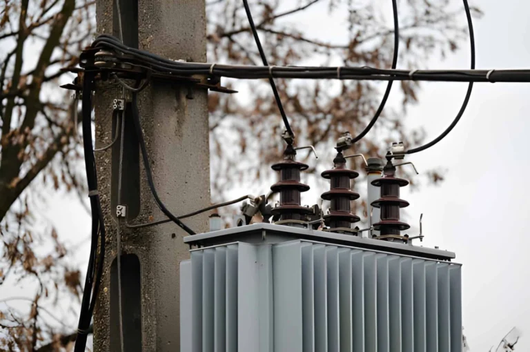
Single-phase units serve lighter, dispersed, or single-phase-only loads. They are common in rural distribution where lines are single-phase, in pole-mounted configurations, and in railway traction systems. While the cost per kVA is higher than a three-phase unit of the same total capacity, a single-phase transformer avoids the expense of running three-phase lines to a light-load area. For detailed selection advice on single-phase oil-type units, see the article on the oil type single phase transformer for smarter distribution.
Phase Configuration Comparison
Factor
Single-Phase
Three-Phase
Typical rating range
5 kVA to ~500 kVA
30 kVA to hundreds of MVA
Cost per kVA
Higher
Lower (shared core)
Transport and installation
Easier, lighter
Heavier, may need crane
Redundancy
Good (parallel units)
Single point of failure
Best for
Rural lines, traction, light commercial, street lighting
Oil immersed transformers serve different roles in the power chain. The application determines the design priorities: voltage ratio, cooling class, tap changer type, protection package, and loss-performance expectations.
Distribution Transformers
These are the most numerous type. They step medium voltage (commonly 6 kV, 10 kV, 11 kV, or 35 kV) down to 400 V for end-use consumption in residential, commercial, and light industrial settings. Typical ratings range from 30 kVA to around 5 MVA. Most are hermetically sealed or compact conservator-type with ONAN cooling. Efficiency is important because distribution transformers run 24/7 even when lightly loaded, so no-load loss is a key specification.
Power Transformers
Power transformers move bulk energy between transmission and distribution voltage levels within substations. Ratings start in the MVA range and extend to hundreds of MVA. They are virtually always conservator-type with ONAF or OFAF cooling, and they include comprehensive protection devices such as Buchholz relays, winding temperature indicators, and online DGA monitoring. Load profiles tend to be high and continuous, so load loss and cooling class are the defining specifications.
Step-Up Transformers
Step-up transformers raise generator output voltage to transmission or sub-transmission level. They are common in power plants, wind farms, and solar parks. Because the generator side sees high current, these units need robust short-circuit withstand. They frequently operate in harsh outdoor conditions with fluctuating loads, so cooling margin and corrosion-resistant tank finishes matter.
Special-Purpose Transformers
Several oil-immersed designs are built for a single industrial duty:
Furnace transformers supply arc or induction furnaces in steelmaking. They handle extreme current, frequent short circuits, and rapid load swings. Shell-type construction and OFAF cooling are common.
Rectifier transformers feed DC loads such as aluminum smelters, electrochemical processes, and industrial DC drives. They are designed for high harmonic content and may include phase-shifting windings.
Traction transformers power railway electrification systems. They are often single-phase, built for mobile or trackside installation, and must tolerate vibration, frequent switching, and wide temperature ranges.
Earthing/grounding transformers provide a neutral point in delta-connected systems for fault current return. These are smaller, specialized units.
Types by Insulating Fluid: Mineral Oil vs Natural Ester vs Synthetic Ester
The fluid inside the tank is a separate design choice from the cooling method or tank type, and it has outsized impact on fire safety, environmental compliance, and long-term operating cost.
Mineral Oil
Highly refined mineral oil is the standard fluid in the vast majority of oil immersed transformers worldwide. It offers excellent dielectric strength (typically 30 to 70 kV breakdown voltage), proven long-term stability, and the lowest fluid cost. The main drawbacks are flammability (flash point around 160 degrees C) and environmental risk in the event of a leak. For most outdoor substation and industrial applications, mineral oil remains the default and most economical choice.
Natural Ester (Vegetable-Based) Oil
Natural ester fluids are derived from renewable sources such as soybean or rapeseed oil. They have a much higher fire point (above 300 degrees C) than mineral oil, are readily biodegradable, and absorb moisture from the cellulose insulation, which can extend paper life. They are increasingly specified for indoor installations, environmentally sensitive sites, and projects where fire containment costs would otherwise be high. The trade-offs are roughly 2 to 3 times higher fluid cost and slightly higher viscosity at low temperatures, which can affect cold-start circulation in extremely cold climates.
Synthetic Ester Oil
Synthetic esters are engineered fluids with performance characteristics similar to natural esters but with better low-temperature behavior and oxidation stability. They are typically more expensive than natural esters but are preferred when the transformer must operate reliably across a very wide temperature range or when maximum oxidation resistance is required over decades of service.
Extreme temperature range, critical infrastructure
Types by Winding Material: Copper vs Aluminum
The conductor material inside the windings affects more than purchase price. It changes the physical size of the transformer, the losses you pay for over its entire operating life, and how the unit handles fault currents.
Copper Windings
Copper has higher conductivity, so copper windings are physically smaller than aluminum windings of the same rating. A smaller coil means a smaller core, a smaller tank, and less oil volume, which reduces the overall footprint and weight of the transformer despite copper being denser. Copper also has higher mechanical strength, which improves short-circuit withstand. The trade-off is higher material cost, which typically makes copper-wound transformers more expensive upfront.
Aluminum Windings
Aluminum windings cost less and weigh less than copper per unit of volume, so the direct material cost is lower. However, aluminum has lower conductivity, meaning the winding cross-section must be larger to carry the same current. This increases core size, tank size, and oil volume. The result is a transformer that is physically larger and heavier overall, even though the conductor itself is lighter. Aluminum is also more susceptible to creep and oxidation at connection points, so termination quality matters more during manufacturing.
Cost-sensitive projects, well-specified standard designs
Voltage Class and Its Influence on Type Selection
Voltage class is not a standalone type, but it heavily constrains which other options are available. Medium-voltage distribution transformers (1 to 36 kV) can be sealed or conservator, single or three-phase, and can use any fluid type. High-voltage power transformers (above 66 kV) are almost exclusively conservator-type, three-phase or single-phase banks, with mineral oil or ester fluid and forced cooling at higher ratings. EHV units above 220 kV nearly always use conservator-type designs with comprehensive monitoring, OFAF or OFWF cooling, and mineral oil.
Understanding this constraint avoids wasted RFQ effort. A buyer who asks for a hermetically sealed transformer at 132 kV is asking for a product that does not exist in standard production, because the oil expansion physics make it impractical. Keeping voltage class in view narrows the type choices to realistic options early in the specification process.
How to Match the Right Type to Your Project: A Decision Framework
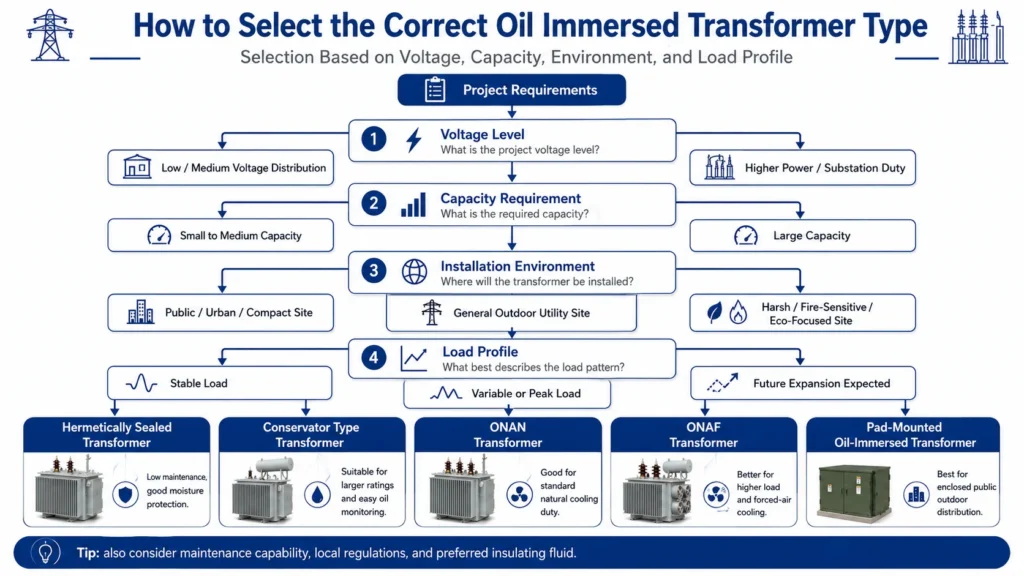
With so many classification dimensions, the practical approach is to work through them in order of priority, starting with what the project demands and eliminating options that do not fit.
Step-by-Step Selection Logic
Confirm the voltage and capacity. This immediately sets the boundary between sealed and conservator, and between ONAN and forced cooling. Below ~5 MVA and 36 kV, sealed ONAN is viable. Above those thresholds, conservator-type with ONAF or OFAF becomes necessary.
Define the load profile. Is the load steady or fluctuating? Are there seasonal peaks? Do short-term overloads occur? This determines whether ONAN is adequate or whether a dual ONAN/ONAF rating provides needed headroom.
Assess the installation environment. Outdoor, indoor, coastal, high-altitude, dusty, hot, cold? Outdoor and coastal sites push toward sealed or conservator with robust finishes. Indoor sites may require ester fluid for fire compliance. High ambient temperature pushes toward forced cooling.
Choose the insulating fluid. If the site has strict fire codes, no secondary containment, or high environmental sensitivity, ester fluids are worth the premium. Otherwise, mineral oil remains the standard.
Decide on winding material. If lifecycle losses matter more than upfront cost, or if space is tight, copper is usually the right call. If capital budget is the primary constraint and the design is standard, aluminum can be acceptable.
Match the phase configuration to the load. Three-phase for balanced industrial and commercial loads; single-phase for rural, traction, or pole-mounted applications.
Select cooling class based on steps 1 through 3. Use the project profile table in the cooling section as a cross-check.
What are the main types of oil immersed transformers?
Oil immersed transformers are classified by cooling method (ONAN, ONAF, OFAF, OFWF), oil preservation (hermetically sealed or conservator-type), phase configuration (single-phase or three-phase), application (distribution, power, step-up, special-purpose), insulating fluid (mineral oil, natural ester, synthetic ester), and winding material (copper or aluminum). Most real-world units combine selections from several of these dimensions.
What is the difference between ONAN and ONAF cooling?
ONAN (Oil Natural Air Natural) relies solely on natural convection and has no fans or pumps. ONAF (Oil Natural Air Forced) adds fans that force air over the radiators when the oil reaches a set temperature. ONAF typically provides 30 to 40 percent more capacity than ONAN in the same tank size, at the cost of fan maintenance and auxiliary power. Many medium-power transformers carry a dual ONAN/ONAF rating.
When should you choose a hermetically sealed transformer instead of a conservator-type?
Choose hermetically sealed for distribution-level ratings (up to about 36 kV and 5 MVA), especially when maintenance access is limited, the site is remote, or the environment is humid or corrosive. Choose conservator-type for higher voltages and capacities where monitoring, oil sampling, and long service life are priorities. Sealed designs minimize moisture entry; conservator designs enable better diagnostics and scalability.
What is the difference between mineral oil and ester oil in transformers?
Mineral oil is the lower-cost standard with good dielectric and cooling performance but is flammable and not biodegradable. Natural ester oil has a fire point above 300 degrees C (versus ~160 degrees C for mineral oil), is biodegradable, and can extend paper insulation life by absorbing moisture, but costs 2 to 3 times more. Synthetic ester offers better low-temperature performance than natural ester at a further premium.
Is copper winding always better than aluminum in an oil immersed transformer?
Not always. Copper offers higher conductivity, smaller physical size, and better short-circuit strength, which matters for space-constrained or critical installations. Aluminum costs less upfront and can be perfectly adequate in well-designed standard distribution transformers where the larger tank size is acceptable. The decision should balance upfront budget against lifecycle losses and physical constraints.
How do distribution transformers differ from power transformers?
Distribution transformers step medium voltage down to utilization voltage (typically 400 V) and range from 30 kVA to about 5 MVA. They are usually ONAN-cooled, often hermetically sealed, and optimized for low no-load loss. Power transformers operate at higher voltages (33 kV and above) from roughly 5 MVA to hundreds of MVA, use conservator designs with forced cooling, and include comprehensive monitoring and protection. They prioritize load loss, cooling margin, and reliability over minimal upfront cost.
Conclusion
The oil immersed transformer family is broad, and the right type for one project can be completely wrong for another even at the same kVA. The differences that matter are cooling class, tank construction, phase configuration, fluid chemistry, and winding material. Each choice shapes the transformer you end up with as an operating asset: how much it costs to buy, how much it costs to run, how often it needs attention, and how many years it lasts.
Start with voltage and capacity to set the boundary conditions, then work through cooling, fluid, winding, and phase in that order. Most practical mistakes come from skipping a dimension, not from choosing the wrong option within one. For a primer on how these types fit into the broader selection and procurement picture, the oil immersed transformer working principle, types, and selection guide is the natural next read. If you have a project specification ready, contact Hairui Electric for a technical consultation and tailored quotation.
An oil immersed transformer is the workhorse of medium- and high-voltage power distribution — the unit you find in substations, industrial plants, and renewable energy projects where cooling capacity, overload margin, and long service life matter more than a compact footprint. Most specification mistakes do not start with the brand or the price. They start […]
At its simplest, an oil immersed transformer (also called an oil filled transformer or oil type transformer) is a static electrical device that transfers energy between circuits through electromagnetic induction, with its active parts fully submerged in insulating oil.
This guide explains how to choose a 10kV oil immersed transformer, compare it with dry type units, evaluate losses, and assess manufacturers for substation and industrial projects.