Offshore Wind 66 kV Collection Systems: Breaker Selection for Salt Spray and Vibration
How 66 kV changed the collection system, what C5-M salt spray demands in measurable terms, and why the breaker boundary runs along the shoreline.
Read More
Ask for an lw8-40.5 and the first thing that needs settling is a naming confusion, because the breaker is sold as a 40.5 kV device and installed on a 35 kV network. The two numbers are not a contradiction. 40.5 kV is the highest voltage for equipment that IEC 62271-1 assigns to a 35 kV system — 35 kV multiplied by the 1.15 highest-voltage factor and rounded into the standard series — and every rating on the datasheet, including the 95 kV power-frequency withstand and the 185 kV lightning impulse level, is referenced to that 40.5 kV figure rather than to the nominal 35 kV the site runs at.
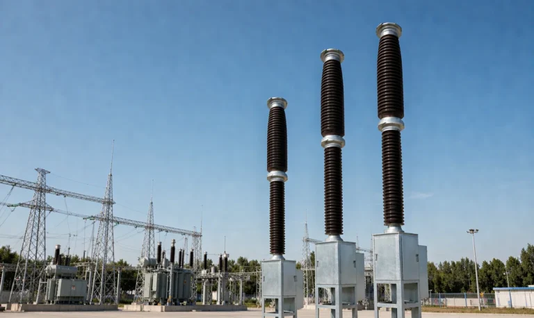
That distinction matters more than it sounds, because it decides what you are actually buying. The lw8-40.5 is a three-pole outdoor porcelain-column breaker with SF6 doing double duty as insulation and arc-quenching medium, a CT14 spring mechanism bolted to the body, and a pressure vessel that holds about 8 kg of gas at 0.5 MPa. It is one of the most widely deployed outdoor breakers in the 35 kV class, which is exactly why the listings are confusing: the same designation covers ratings from 20 kA to 40 kA, currents from 1600 A to 3150 A, and mechanical lives quoted anywhere between 3000 and 5000 operations depending on which factory built it.
This article works through the three numbers that actually decide a 35 kV order — 2000 A, 0.5 MPa and 3000 operations — and shows where each one binds, where it is generous, and where it is a limit that has to be checked against the site rather than assumed. It also sets out the honest case for and against choosing this breaker over a vacuum alternative, because at 40.5 kV that comparison is no longer a formality.
The insulation numbers on an LW8-40.5 datasheet look arbitrary until they are read against the standard. For equipment with a highest voltage of 40.5 kV, IEC 62271-1 sets the rated short-duration power-frequency withstand at 95 kV rms to earth and the rated lightning impulse withstand at 185 kV peak to earth. Across the isolating distance — between the contacts of an open breaker — the levels rise to 118 kV rms and 215 kV peak.
An LW8-40.5 quotes exactly those to-earth values: 95 kV and 185 kV. The across-gap figures appear as 95 + 24 kV and 185 + 33 kV, which bracket the standard’s 118 kV and 215 kV rather than exceeding them by a wide margin. This is worth stating plainly because it is the opposite of what some other models in the same range do. Where a 72.5 kV model often quotes 160 kV power frequency and 350 kV impulse against a 140 kV and 325 kV floor, the 40.5 kV model sits on the standard line. It is compliant, not over-insulated.
| Insulation parameter | IEC 62271-1 for Um 40.5 kV | LW8-40.5 specification | Reading |
|---|---|---|---|
| Power frequency, to earth | 95 kV rms | 95 kV rms | On the standard line, no margin |
| Power frequency, across open gap | 118 kV rms | 95 + 24 kV rms | Brackets the standard value |
| Lightning impulse, to earth | 185 kV peak | 185 kV peak | On the standard line, no margin |
| Lightning impulse, across open gap | 215 kV peak | 185 + 33 kV peak | Brackets the standard value |
| Rated short-circuit duration | 1 s or 3 s | 3 s or 4 s depending on variant | Confirm against the protection clearing time |
The practical consequence is that an LW8-40.5 leaves you no headroom for a high-altitude site, a heavily polluted site or a utility that applies its own coordination margin on top of the standard. Those cases are handled by ordering a configured variant rather than by relying on the base rating, which is why the altitude and pollution levers later in this article are not optional extras. The same discipline applies to reading the lightning impulse variant, where the impulse level is the whole point of the listing.
Two thousand amperes sounds like a distribution rating, and on a 35 kV network it usually is not. A typical 35 kV overhead feeder carries somewhere between 200 A and 600 A, and a 35 kV cable feeder rarely exceeds 400 A. At 2000 A the breaker is carrying five times what a normal feeder needs, which tells you where it actually belongs: the incomer bay at the receiving end of a 110/35 kV transformer, a bus section, or a tie between two 35 kV boards.
The arithmetic behind the choice is simple. A 50 MVA transformer at 35 kV has a rated secondary current of about 824 A, so a 1600 A incomer breaker already covers it with headroom for a 1.1 times overload check. The 2000 A rating comes into play when two transformers run in parallel on one board, when a bus section has to carry the load of an adjacent section after a transformer outage, or when a mine or a smelter has a single 35 kV bus with several large drives on it. That is the case the 2000 A variant is built for.
There is a second reason to think about current rating before breaking capacity, and it is thermal rather than electrical. The 2000 A configuration uses heavier primary conductors and larger terminal pads than the 1600 A, so the contact resistance and the temperature rise at rated current are the same 65 K class rather than a stretched 1600 A design running near its limit. The medium-mounted 40.5 kV listing is the one that carries both current options on a single specification, which makes the comparison easier to read. If a buyer expects the board to grow, buying the 2000 A body at the outset is cheaper than replacing a 1600 A breaker three years later — and it is the only upgrade on this breaker that cannot be done in the field.
The headline figure is a rated pressure of 0.5 MPa gauge at 20 °C, and most procurement documents stop there. What actually governs operation is the ladder around it: the rated pressure the breaker is designed to interrupt at, the alarm pressure that warns you it has dropped, and the minimum functional pressure below which the interrupting duty can no longer be guaranteed.
On this model the alarm is set at 0.47 MPa — only 6 percent below rated. Read as a percentage the band looks tight; read as time it is generous. At the 1 percent per year leakage limit that the datasheet allows, the gas mass falls about 1 percent a year, which moves pressure by roughly 0.005 MPa a year. Travelling the 0.03 MPa from rated to alarm at that rate would take six years. Which is the useful conclusion: a slow permeation leak will not trip the alarm within the life of the asset, so when the alarm does appear it is almost always a discrete event — a gasket that has taken a set, a seal that has been disturbed during a site top-up, a flange that was not re-torqued.

| Pressure level | Value at 20 °C | What it means operationally |
|---|---|---|
| Rated filling pressure | 0.5 MPa gauge | Reference condition for both insulation and interrupting performance |
| Alarm | 0.47 MPa gauge | Schedule a top-up; the breaker still performs its full duty |
| Minimum functional pressure | Quoted in the listing; confirm on the type-test report | Floor below which the interrupting rating is void — this is the lockout reference, not the alarm |
| Gas mass per breaker | About 8 kg | Sets the top-up logistics and the CO2-equivalent footprint of the asset |
| Moisture limit | ≤150 ppmv | Checked after every top-up, because topping up with wet gas is the usual route to a moisture problem |
The gap between alarm and minimum functional pressure is the operating window, and it is where most of the field confusion lives. Two things are worth insisting on in the technical agreement. First, the lockout contact must be set from the type-test report rather than copied from a marketing table, because the interrupting rating is lost well before the dielectric strength is. Second, the alarm and lockout contacts must not share a circuit — an alarm that also blocks closing turns a routine top-up into an outage. The 0.5 MPa pressure variant is the listing where this ladder is documented in full.
The 3000-operation figure is mechanical endurance, and it is the number buyers quote most often and understand least. It counts spring charge, close, trip and latch cycles with no current flowing. It says nothing about how many times the breaker can interrupt fault current, and the two figures on this family are far apart.
The electrical endurance is quoted as a cumulative count of full short-circuit interruptions at rated breaking current — 12 to 20 breaks depending on the rating variant, with the 40 kA version at the lower end because each interruption removes more contact material. Put the two numbers side by side and the design intent becomes clear. The mechanism is built to be operated thousands of times on load and a few dozen times on fault, which is exactly the duty profile of a distribution incomer or a bus tie.
Where the 3000 figure starts to matter is on feeders that are switched daily rather than monthly — wind farm collector circuits, capacitor banks on a voltage-control schedule, or a bus tie in a network with frequent reconfiguration. Three thousand operations at two operations a day is four years. That is the honest case for stepping up to a variant with a longer mechanical life, and the 3000-operation listing is where the endurance statement and the mechanism type are documented together. It is also the point where a vacuum alternative starts to compete, because vacuum interrupters in this voltage class are commonly rated for 10,000 to 30,000 mechanical operations.
The bay position decides more of the specification than the load calculation does, because each position has a different duty mix. An incomer sees load current continuously and interrupts fault current rarely. A bus tie sees almost no current in normal operation but must survive a transfer with the full section load behind it. A capacitor bank breaker interrupts capacitive current every day and is the position where restrike matters most.
| 35 kV bay position | Dominant duty | What to specify |
|---|---|---|
| Transformer incomer | Continuous load, occasional fault clearing | 2000 A, breaking capacity matched to the transformer plus the bus contribution |
| Outgoing feeder | Load switching, fault clearing, reclosing | 1600 A is usually enough; confirm the auto-reclose sequence |
| Bus section or tie | Transfer current, close-open duty | 2000 A and the rated close-open sequence, not just the breaking current |
| Capacitor bank | Daily capacitive switching | 400 A single-bank rating and a restrike-free interrupter |
| Wind or PV collector | Frequent switching, low load current | Mechanical life and the number of daily operations |
| Mine or industrial bus | High fault level, harsh environment | Higher breaking capacity, pollution class III or IV, sealed tank |

The 40 kA variants deserve a note of scepticism here. Fault level at a 35 kV bus is usually lower than buyers expect: a 50 MVA 110/35 kV transformer with 10.5 percent impedance delivers about 7.9 kA at the 35 kV terminals, and even three such transformers in parallel only reach the low twenties. A 25 kA or 31.5 kA rating covers the overwhelming majority of distribution substations. The 40 kA configuration exists for buses with local generation, large motor contributions or several transformers solidly paralleled, and paying for it on a conventional substation is money spent on a rating the site will never produce. The LW series model comparison sets that 40.5 kV decision against the 72.5 kV and 126 kV classes if the site is on the boundary between voltage levels.
At 40.5 kV the SF6 versus vacuum question is genuinely open, and the answer depends on duty rather than on preference. Vacuum interrupters dominate new indoor metal-clad switchgear in this class because they are cheaper, need no gas handling and reach 10,000 to 30,000 mechanical operations. An outdoor porcelain-column SF6 breaker wins in a narrower but real set of conditions.
| Criterion | LW8-40.5 SF6 | 40.5 kV vacuum | Who wins |
|---|---|---|---|
| Purchase price at 25 kA | Higher — gas system, sealed tank, density monitor | Lower | Vacuum |
| Mechanical endurance | 3000 operations typical | 10,000 to 30,000 operations | Vacuum |
| Breaking capacity at the top of the class | Up to 40 kA with 100 kA peak | Typically 31.5 kA in outdoor column designs | SF6 |
| Capacitor bank switching | 400 A single bank, restrike-free by design | Restrike risk rises at 40.5 kV; needs surge control | SF6 |
| Polluted or humid site | Interrupter sealed inside a gas tank | Interrupter sealed, external insulation still exposed | Marginal — depends on the bushing |
| Maintenance skill required | Gas cart, density relay, moisture testing | Vacuum tester, contact resistance meter | Vacuum |
| Regulatory exposure | GWP of 23,500; EU 24–52 kV band closes to new SF6 switchgear in 2030 | None | Vacuum |
Read that table as a set of conditions rather than a score. If the site needs 31.5 kA or more, switches a capacitor bank daily, sits in a coastal or heavily polluted yard, and the buyer is not selling into the European Union, the LW8-40.5 is the better engineering answer and the cost difference is small against the rest of the bay. If the site is a conventional distribution substation at 25 kA with a few hundred operations a year, a vacuum breaker will be cheaper to buy, cheaper to keep and easier to defend on environmental grounds. The SF6 versus vacuum comparison goes through the physics behind those rows if the decision is contested inside the project team.
Because the base rating sits on the standard line rather than above it, any site condition that erodes insulation margin has to be answered by configuration. There are three levers, and they are independent.
Six items settle almost every LW8-40.5 enquiry, and getting them into the request for quotation is what separates a one-round order from a four-round one.
The LW8-40.5 is a mature, unglamorous breaker, and that is its appeal. It is not over-insulated, it does not promise margin it does not have, and its 2000 A and 0.5 MPa figures are engineering limits you can design against once you know what each one means. The buyers who get into trouble with it are the ones who specify 40 kA on a 8 kA bus, or who accept a gas pressure ladder they have never read, or who buy 3000 mechanical operations for a feeder that switches twice a day. None of those are product faults. They are specification faults, and all three are avoidable before the order is placed. For the rest of the range, the SF6 circuit breaker articles cover the other voltage classes and the duty ratings that sit behind this one.
Yes in practice. 40.5 kV is the highest voltage for equipment assigned to a 35 kV system, so the breaker is installed on 35 kV networks and every rating on its datasheet is referenced to 40.5 kV. A 35 kV site never applies 40.5 kV, which is exactly why the rating has margin built into the definition rather than into the product.
Because they are different voltage classes. IEC 62271-1 sets 95 kV power frequency and 185 kV impulse for Um 40.5 kV, and 140 kV and 325 kV for Um 72.5 kV. The LW8-40.5 quotes the 40.5 kV values exactly, so it is compliant without extra margin — a 72.5 kV model quoting 160 kV is a step above its own floor.
The breaker may still hold voltage, because dielectric strength falls more slowly than interrupting capability, but its rated breaking current is no longer guaranteed. That is why the lockout setpoint must come from the type-test report and sit above the floor rather than at it, and why the alarm and lockout contacts should never share a circuit.
Yes, with a rated single-bank capacitive breaking current of 400 A. That figure is what to check against the bank’s actual current rather than the bank’s nominal Mvar, because the current at the operating voltage is what the interrupter has to break.
No. It is mechanical endurance with no current flowing. Electrical endurance is a separate rating quoted as 12 to 20 full interruptions at rated breaking current depending on the variant, and the two numbers describe completely different wear mechanisms.
Rarely. A 50 MVA 110/35 kV transformer with 10.5 percent impedance produces about 7.9 kA at the 35 kV bus, so 25 kA covers most distribution substations and 31.5 kA covers the rest. The 40 kA variants are for buses with local generation, heavy motor contribution or several transformers solidly paralleled.