Control Transformer Wiring Schematic: A Complete Guide
Published: Author: Lisa
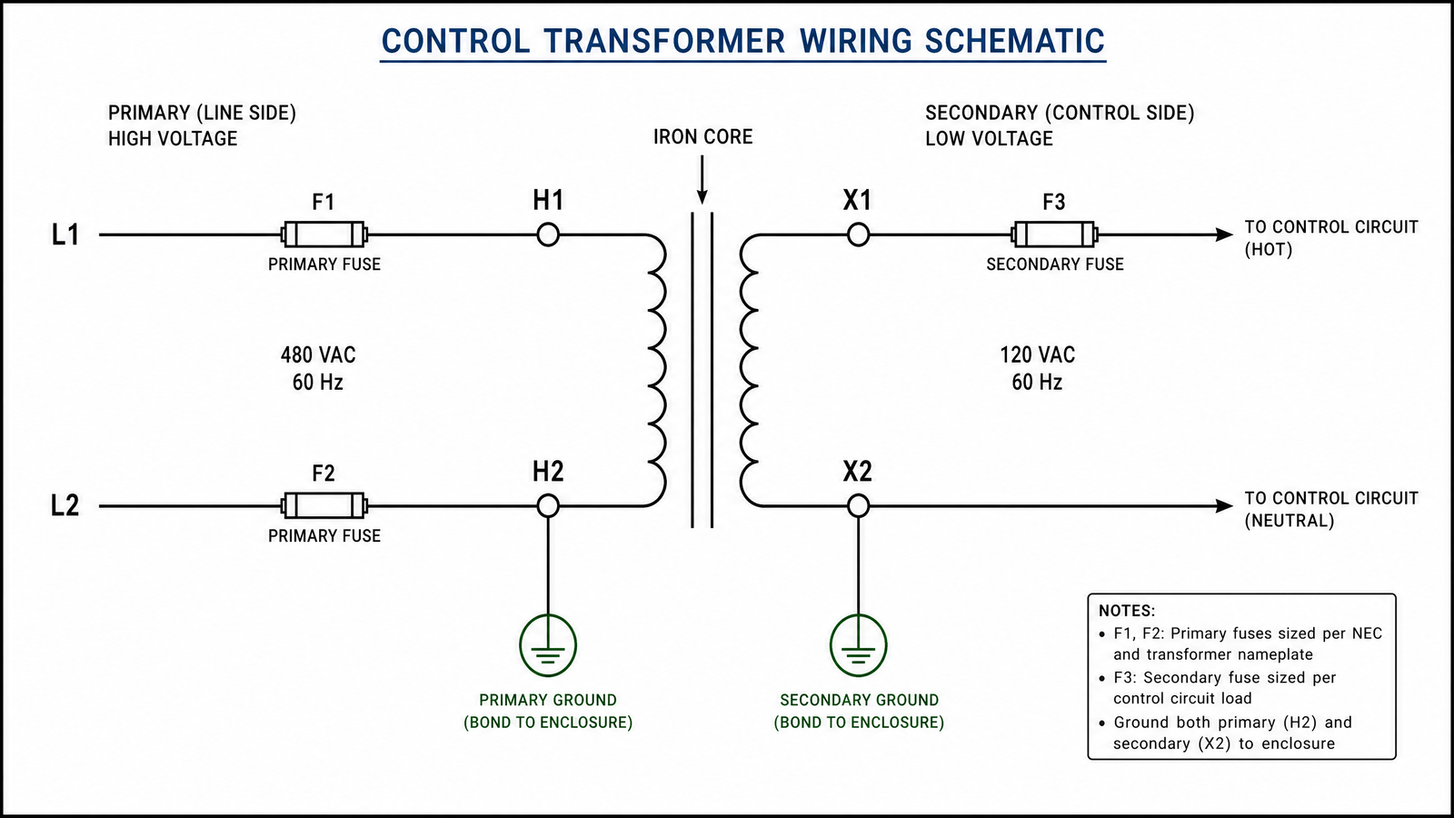
A control transformer wiring schematic
is the diagram that shows how a control transformer’s primary winding connects to the
incoming supply and how its secondary winding feeds a low-voltage control circuit —
contactors, relays, PLC inputs, and pilot lights. It is the reference you follow to step
line voltage down to a safe, isolated control voltage, usually 110 V, 220 V, or
24 V, without damaging equipment or tripping protection.
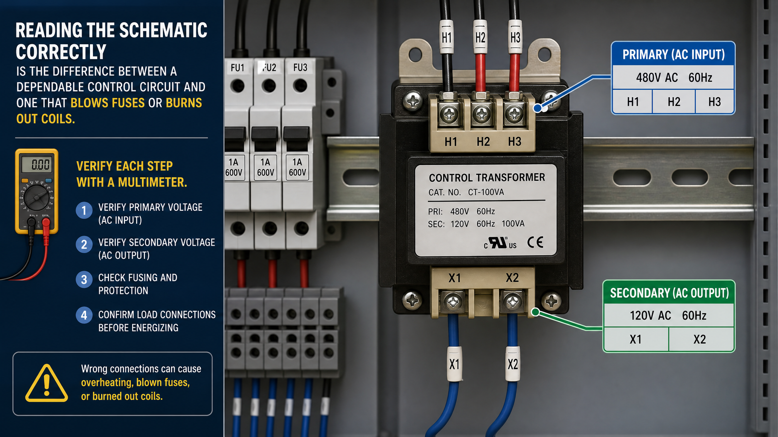
Reading this schematic correctly is the difference between a dependable control circuit
and one that blows fuses or burns out coils. This guide from
Hairui Electric explains the symbols, the
terminal markings, and a practical reading sequence you can apply to any control
transformer.
What a Control Transformer Wiring Schematic Shows
A wiring schematic is a simplified electrical drawing, not a physical layout. It shows
the transformer as two coils — the primary winding on the line side
and the secondary winding on the control side — linked by an iron
core. The primary is drawn toward the supply, and the secondary is drawn toward the
control load.
A complete schematic normally includes:
Primary terminals (H1, H2, and often H3, H4) that receive the incoming line voltage.
Secondary terminals (X1, X2, and often X3, X4) that deliver the reduced control voltage.
Protection devices , such as primary fuses or a secondary circuit breaker.
Grounding points for the core and enclosure.
Optional taps that let one transformer serve more than one voltage.
Schematic Symbols and Terminal Markings
Terminal lettering follows a simple convention that makes wiring less error-prone.
H marks the higher-voltage (primary) side and X marks the
lower-voltage (secondary) side. Many control transformers split the primary into two
windings marked H1–H2 and H3–H4, and the secondary
into X1–X2 and X3–X4.
H1, H2 — first primary winding connections.
H3, H4 — second primary winding connections, used for dual-voltage wiring.
X1, X2 — first secondary winding connections, the control output.
X3, X4 — second secondary winding connections, when a multi-tap output is provided.
Around the windings, expect standard symbols: two parallel lines for the magnetic core,
circles or rectangles for the windings, a fuse symbol on the primary feed, and a ground
symbol where the core or panel must be bonded to earth.
How a Control Transformer Works
A control transformer is a step-down transformer. When line voltage is applied to the
primary winding, it produces a changing magnetic flux in the iron core. That flux induces
a proportionally lower voltage in the secondary winding, set by the turns ratio. A unit
with roughly a 3.5:1 turns ratio, for example, converts a 380 V input into about
110 V at the secondary while still isolating the control circuit from the supply.
Two properties make it ideal for automation. First, it provides galvanic
isolation, so a line-side fault does not pass into sensitive control electronics.
Second, it delivers a stable, lower voltage that keeps relay and
contactor coils within their design range even when the supply fluctuates.
How to Read a Control Transformer Wiring Schematic
Most wiring mistakes happen because someone rushes to connect terminals before confirming
the voltages. Follow this sequence and verify each step with a multimeter.
Confirm the ratings. Check that the nameplate input voltage matches your supply and the output matches the control load.
Identify the primary. Find H1–H2 (and H3–H4 on a dual-primary unit) on the line side of the schematic.
Identify the secondary. Find X1–X2 (and any X3–X4 taps) on the control side.
Trace the protection. Locate the fuses or breaker and confirm they are sized to the transformer’s rated current.
Check the ground bond. Confirm the core and enclosure grounding points before energizing.
Test before energizing. With the secondary load disconnected, verify the no-load output voltage, then reconnect and re-test under load.
Common Wiring Configurations
The same transformer can often be wired several ways, which is exactly why the schematic
matters. The table below summarizes the configurations you will most often encounter.
Configuration
Primary connection
Secondary output
Typical use
Single-voltage primary
220 V across H1–H2
110 V
General machine tool control circuits
Dual-primary, series
380 V across series windings
110 V or 220 V
Three-phase-fed control panels
Dual-primary, parallel
220 V across parallel windings
24 V
PLC and low-voltage automation supplies
Multi-tap secondary
220 V or 380 V
24 / 110 / 220 V selectable
Mixed loads on a single transformer
Control Transformer Types Compared
The right control transformer depends on capacity, mounting style, and how quiet and
efficient the circuit must be.
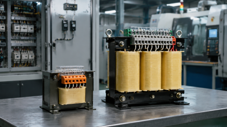
Low-noise applications such as medical and audio (featured)
The R-Type Transformer for Low-Noise Circuits
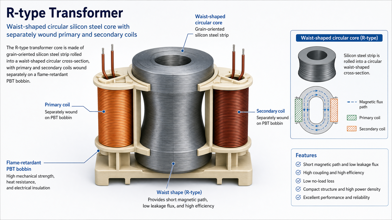
The
R-type transformer
is a newcomer among dry-type control transformers, and its construction changes how it
behaves in a schematic. Its core is made of grain-oriented, cold-rolled silicon steel
strip of varying widths, rolled into a waist-shaped circular cross-section so it can be
wound without cutting. The result is a transformer that is quiet, with low magnetic flux
leakage, low no-load current, low iron loss, and high efficiency.
Its cylindrical coils and short copper wire length per turn produce low internal
resistance, low copper loss, low temperature rise, and minimal overload fluctuation. The
primary and secondary coils are wound separately on a flame-retardant PBT engineering
plastic bobbin, giving high electrical strength and excellent flame retardancy. These
qualities make the R-type especially suitable for medical equipment, display devices,
audio equipment, and office equipment, with a 220 V or 380 V input and a
customizable output.
Common Wiring Mistakes to Avoid
Reversing primary and secondary. Feeding line voltage into X1–X2 can destroy the winding and everything downstream.
Omitting fuses. Running the primary or secondary without protection turns a minor short into a burned-out transformer.
Choosing the wrong tap. Connecting a 110 V coil to a 220 V tap under- or over-voltages the control load.
Under-sizing the transformer. Ignoring coil inrush current leads to voltage sag and contactors that will not pull in reliably.
Skipping the ground bond. An unbonded core is a shock and noise hazard in an industrial panel.
Not testing first. Energizing without a no-load voltage check risks the whole control circuit on a wiring assumption.
Frequently Asked Questions
What is a control transformer wiring schematic?
It is a drawing that shows how the primary and secondary windings of a control
transformer connect to the supply and to the low-voltage control devices, along with
fuses and grounding points.
What do H1, H2, X1, and X2 mean?
H terminals are the higher-voltage primary connections and X
terminals are the lower-voltage secondary connections. H1–H2 receives the line, and
X1–X2 supplies the control circuit.
How do I wire a 380 V to 110 V control transformer?
Connect the two primary windings in series for 380 V input, then take 110 V from
the secondary terminals X1–X2, adding fuses on the primary side before energizing.
What is the difference between a schematic and a wiring diagram?
A schematic shows electrical connections and logic without physical placement, while a
wiring diagram shows the actual physical connections and terminal locations. Both are
used together when installing a control transformer.
Do control transformers need a fuse on the secondary?
Yes. A primary fuse protects the transformer itself, while a secondary fuse or breaker
protects the control wiring and the devices it feeds. Both are recommended in most panels.
Wire It Right the First Time
A control transformer wiring schematic is not just a formality — it is the reference
that keeps your control voltage isolated, stable, and safe. Read the terminal markings,
confirm the voltages, protect both windings, and test with a meter before you power up.
To compare capacities and mounting styles, you can
browse the full catalog or learn more
about our company’s control transformer
range. If you are unsure which tap or capacity your application needs,
contact us for a tailored
recommendation, or return to the home page to
see the complete product range.
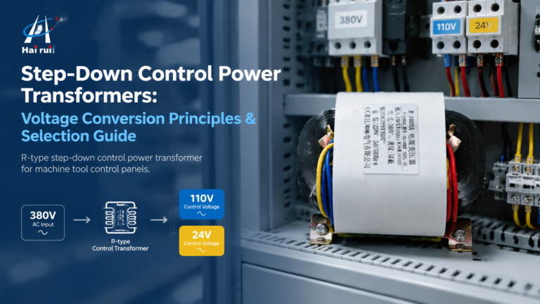
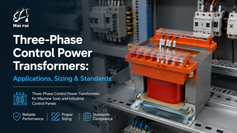
How step-down control power transformers convert 380V/480V line voltage to 110V or 24V control power: turns ratio, VA sizing with inrush, voltage-drop behaviour, wiring and selection.
How three-phase control power transformers work, how to size them for machine tool and control-panel loads, and the delta/wye, standards and protection choices that matter in the field.