Control Transformer Wiring Diagram A Step-by-Step Guide
Published: Author: Lisa
A control transformer wiring diagram is the schematic that shows how a control transformer’s primary winding connects to the incoming line and how its secondary winding feeds the low-voltage circuit that powers contactors, relays, PLC inputs, and pilot lights. In plain terms, it is the wiring map you follow so the transformer steps line voltage down to a safe, isolated control voltage — usually 110 V, 220 V, or 24 V — without damaging equipment or tripping protection.
Reading this diagram correctly is the difference between a dependable control circuit and one that blows fuses or burns out coils. This guide explains the terminal markings, the symbols, and a practical wiring sequence you can apply to a machine tool control transformer.
What Does a Control Transformer Wiring Diagram Show?
A control transformer wiring diagram is a simplified electrical schematic, not a physical layout. It represents the transformer as two coils — the primary winding on the line side and the secondary winding on the control side — separated by an iron core, with the primary drawn to the supply and the secondary drawn to the control load, such as a contactor coil.
The diagram normally includes the following details:
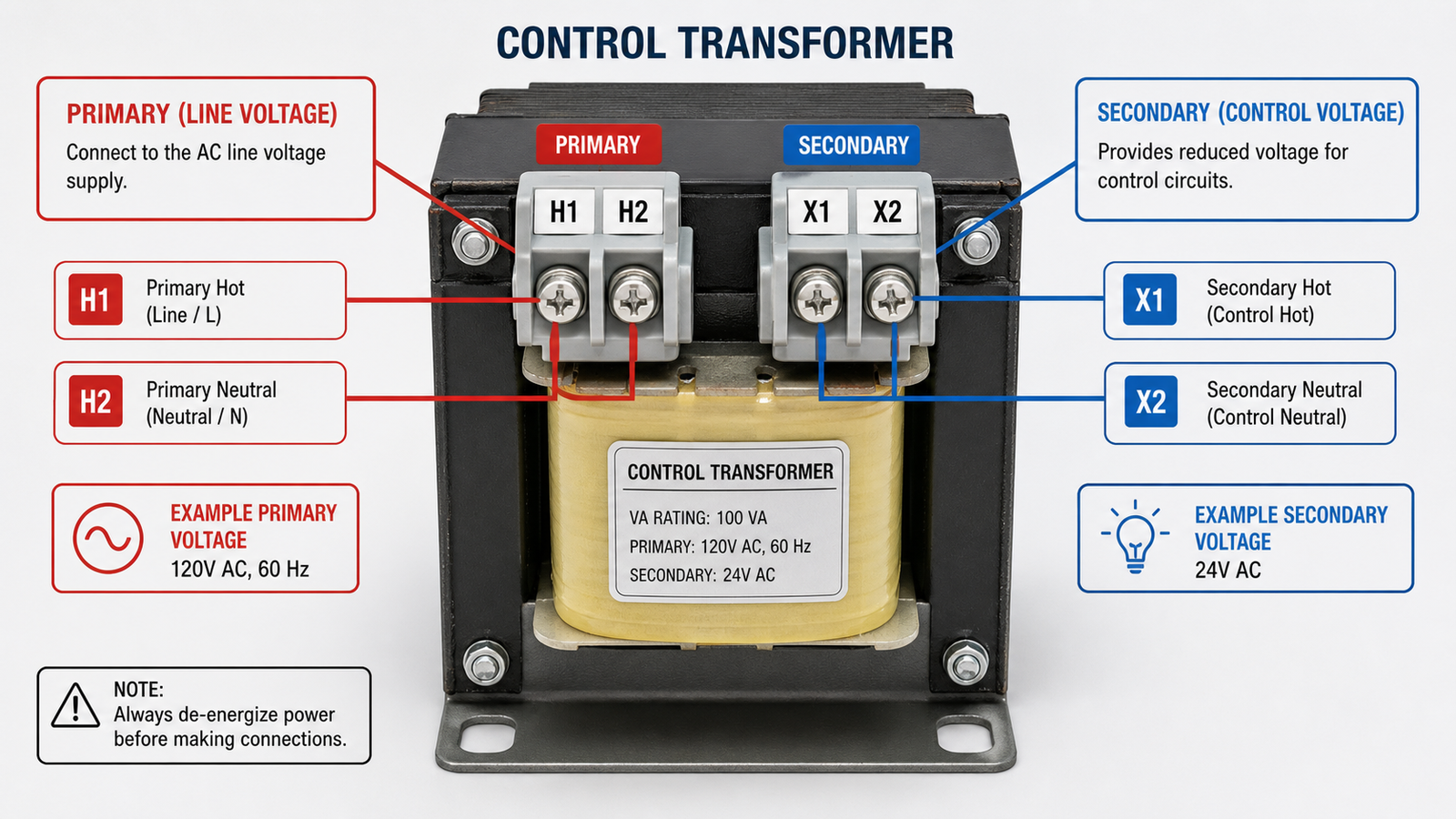
Primary terminals (H1, H2, and often H3, H4) that receive the incoming line voltage.
Secondary terminals (X1, X2, and often X3, X4) that deliver the reduced control voltage.
Protection devices , such as primary fuses or a secondary circuit breaker.
Grounding points for the core and enclosure.
Optional taps that allow the same transformer to be used at more than one voltage.
Terminal Markings and Symbols You Will See
Terminal lettering follows a simple convention that makes wiring far less error-prone. H stands for the higher-voltage (primary) side, and X stands for the lower-voltage (secondary) side. On many machine tool control transformers, the primary is split into two windings marked H1–H2 and H3–H4, and the secondary is split into X1–X2 and X3–X4.
H1, H2 — first primary winding connections.
H3, H4 — second primary winding connections (used for dual-voltage wiring).
X1, X2 — first secondary winding connections (the control output).
X3, X4 — second secondary winding connections, when a multi-tap output is provided.
Beyond the terminals, expect to see standard electrical symbols: two parallel lines for the magnetic core, circles or rectangles for the windings, a fuse symbol on the primary feed, and a ground symbol where the core or panel must be bonded to earth.
How a Control Transformer Works
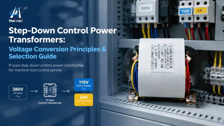
A control transformer is a step-down transformer. When line voltage is applied to the primary winding, it produces a changing magnetic flux in the iron core. That flux induces a proportionally lower voltage in the secondary winding, according to the turns ratio. A transformer built with roughly a 3.5:1 turns ratio, for example, converts a 380 V input into about 110 V at the secondary, while still isolating the control circuit from the supply.
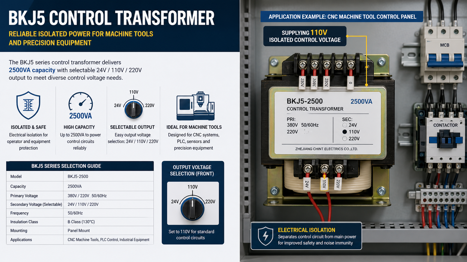
Two properties make it ideal for machine tools and automation. First, it provides galvanic isolation, so a line-side fault does not pass into the sensitive control electronics. Second, it delivers a stable, lower voltage that keeps relay and contactor coils within their design range even when the supply fluctuates. The BKJ5 Machine Tool Control Transformer, for instance, is built with a silicon steel core and copper windings and is rated for a 220 V or 380 V input with a 24 V, 110 V, or 220 V output, depending on the selected taps.
How to Wire a Control Transformer: Step by Step
Most wiring mistakes happen because someone rushes to connect terminals before confirming the voltages. Follow this sequence and verify each step with a multimeter.
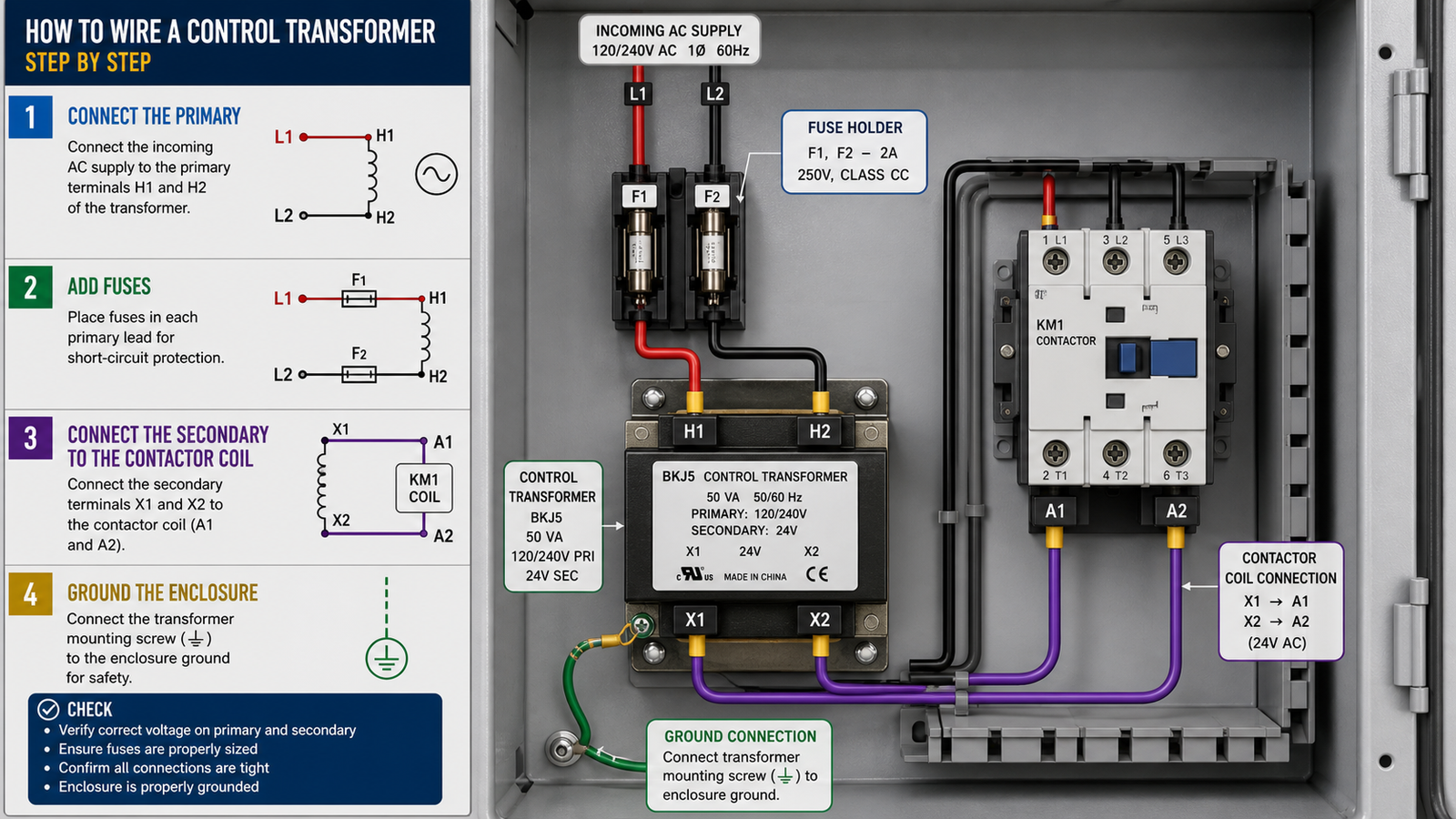
Confirm the ratings. Check that the nameplate input voltage matches your supply and that the required output voltage matches the control load.
Connect the primary. Wire the incoming line to the primary terminals. For a single-voltage primary, connect to H1 and H2. For a dual-primary unit, connect the two primary windings in series for the higher voltage or in parallel for the lower voltage.
Add primary protection. Install fuses or a breaker on the line side, sized to the transformer’s inrush and rated current.
Connect the secondary. Take the control voltage from X1 and X2 and run it to the control circuit — the contactor coil, relay, or PLC power terminals.
Bond the enclosure. Ground the core and the panel per the diagram, then double-check all screw terminals are tight.
Test before energizing. With the secondary load disconnected, confirm the correct no-load output voltage, then reconnect the load and re-test under load.
Units like the BKJ5 use screw terminal connections and support vertical or horizontal mounting, which makes this sequence straightforward even inside a crowded panel.
Common Wiring Configurations
The same transformer can often be wired several ways, which is exactly why the diagram matters. The table below summarizes the configurations you will most often encounter on a machine tool control transformer.
Configuration
Primary connection
Secondary output
Typical use
Single-voltage primary
220 V across H1–H2
110 V
General machine tool control circuits
Dual-primary, series
380 V across series windings
110 V or 220 V
Three-phase-fed control panels
Dual-primary, parallel
220 V across parallel windings
24 V
PLC and low-voltage automation supplies
Multi-tap secondary
220 V or 380 V
24 / 110 / 220 V selectable
Mixed loads on a single transformer
Control Transformer Types Compared
The right control transformer depends on capacity, mounting style, and how quiet and efficient the circuit must be.
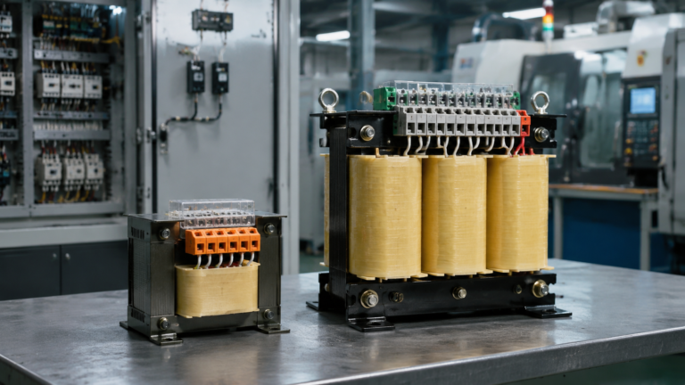
For heavy machine tool loads, the BKJ5 is a common starting point because of its 2500VA capacity and its selectable 24/110/220 V output, which covers the full range of relay, contactor, and PLC control voltages in a single unit.
Common Wiring Mistakes to Avoid
Even experienced electricians make these mistakes when they skip the diagram.
Reversing primary and secondary. Feeding line voltage into X1–X2 can destroy the winding and everything downstream.
Omitting fuses. Running the primary or secondary without protection turns a minor short into a burned-out transformer.
Choosing the wrong tap. Connecting a 110 V coil to a 220 V tap under- or over-voltages the control load.
Under-sizing the transformer. Ignoring coil inrush current leads to voltage sag and contactors that will not pull in reliably.
Skipping the ground bond. An unbonded core is a shock and noise hazard in an industrial panel.
Not testing first. Energizing without a no-load voltage check risks the whole control circuit on a wiring assumption.
Wire It Right the First Time
A control transformer wiring diagram is not just a formality — it is the reference that keeps your control voltage isolated, stable, and safe. Read the terminal markings, confirm the voltages, protect both windings, and test with a meter before you power up. For more detail on selecting a unit for a specific machine, you can browse the full catalog or explore the range of our company’s control transformer products to compare capacities and mounting styles. If you are unsure which tap or capacity your application needs, contact us for a tailored recommendation, or return to the home page to see the complete product range.
Frequently Asked Questions
What is a control transformer wiring diagram?
It is a schematic that shows how the primary and secondary windings of a control transformer connect to the supply and to the low-voltage control devices, along with fuses and grounding points.
What do H1, H2, X1, and X2 mean?
H terminals are the higher-voltage primary connections and X terminals are the lower-voltage secondary connections. H1–H2 receives the line, and X1–X2 supplies the control circuit.
How do I wire a 380 V to 110 V control transformer?
Connect the two primary windings in series for 380 V input, then take 110 V from the secondary terminals X1–X2, adding fuses on the primary side before energizing.
Do control transformers need a fuse on the secondary?
Yes. A primary fuse protects the transformer itself, while a secondary fuse or breaker protects the control wiring and the devices it feeds. Both are recommended in most panels.
Can a control transformer be wired in reverse?
Technically a transformer can be back-fed, but it is not recommended for control transformers because voltage regulation, inrush, and terminal ratings are designed for the labeled direction. Always wire primary to the line and secondary to the load.
What control voltage should I use for PLC power?
Most PLCs run on 24 V DC or 110 V AC depending on the model. Check the PLC supply rating and match it to the transformer’s secondary tap, which is why selectable outputs such as 24/110/220 V are useful.
How step-down control power transformers convert 380V/480V line voltage to 110V or 24V control power: turns ratio, VA sizing with inrush, voltage-drop behaviour, wiring and selection.
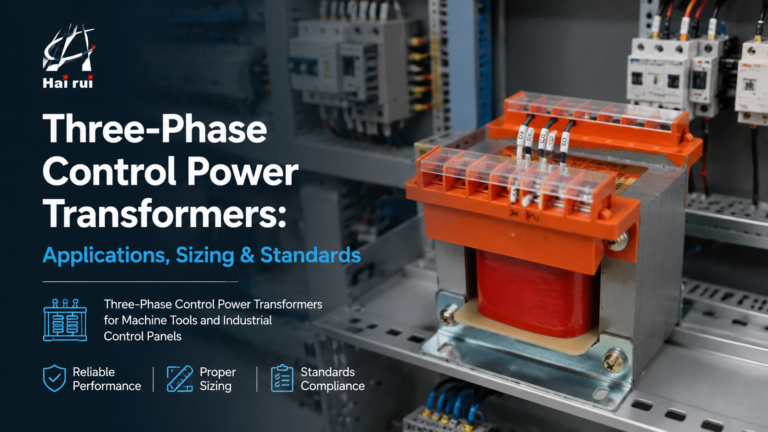
How three-phase control power transformers work, how to size them for machine tool and control-panel loads, and the delta/wye, standards and protection choices that matter in the field.