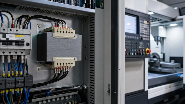
Three-Phase Control Power Transformers: Applications, Sizing & Standards
Published: Author: Lisa
If your machine or control panel runs from a three-phase supply at 208 V, 380 V, 400 V or 480 V, the component that steps that power down to a safe level for contactors, PLCs, solenoids and instruments is a three phase control power transformer. Unlike a single-phase unit, it converts all three lines together and keeps the control network properly fed even when phase-to-phase loads such as motor-operated valves or heater banks switch on.
This guide covers what three-phase control transformers are, where they are used, how to size them with the correct kVA formula, and which wiring and standards questions to ask before you buy.
What Is a Three-Phase Control Power Transformer?
A three-phase control power transformer is a low-voltage, dry-type transformer that supplies control and auxiliary circuits from a three-phase network. Its primary connects to the line voltage (for example 3 × 380 V or 3 × 480 V), and its secondary provides a lower, isolated voltage such as 3 × 220 V, 3 × 110 V or 3 × 24 V for the control loop. The magnetic core carries three sets of primary and secondary windings on a common limb, so all three phases are transformed together.
Three things separate these units from general power transformers:
Load profile: they are designed for the momentary inrush of electromagnetic devices — contactor coils, solenoids, relays — while holding secondary voltage drop within an acceptable window.
Isolation: the secondary winding is galvanically isolated from the primary line, which protects operators and reduces conducted noise entering sensitive controllers.
Construction: typical enclosures, terminal arrangements and mounting styles are built for installation inside control cabinets rather than on substation pads.
Ratings are usually expressed in VA or kVA rather than kW, because the load is a mix of resistive and inductive devices with a low and shifting power factor.
Typical Applications for Three-Phase Control Transformers
Anywhere a three-phase installation needs a dependable low-voltage control supply, a three-phase control transformer is a candidate. Common applications include:
Machine tool and CNC auxiliary control circuits on 380–480 V shop floors.
HVAC and pump control panels that operate contactors, starters and damper actuators on three-phase equipment.
Motor control centers (MCCs) where the control bus must stay live and stable for metering, protection relays and indication.
Packaging, conveying and process lines with distributed push-button and sensor circuits fed from a central transformer.
Enclosure power for lighting, socket outlets and space heaters inside large switchgear and control cubicles.
Projects that need a clean, isolated auxiliary supply for PLC racks or instrumentation where the site only has a three-phase feed.
In each case the transformer is sized for the sum of the control loads plus the inrush they draw when energized, not for the main power that the motor or heater consumes.
Single-Phase vs Three-Phase Control Transformers: Key Differences
The choice between the two usually comes down to the supply available at the panel and whether the control loop itself must be referenced to three phases. We have covered the general decision in detail in our single-phase vs three-phase control power transformer guide; the table below summarizes the points that matter when a three-phase unit is under consideration.
Aspect
Single-phase control transformer
Three-phase control transformer
Supply connection
One line-to-line or line-to-neutral pair
Three lines (delta or wye)
Typical secondaries
120 V, 110 V, 24 V, 12 V
3 × 220 V, 3 × 110 V, 3 × 24 V (often with neutral)
Sizing formula
VA = V × A
kVA = (VLL × A × √3) / 1000
Typical ratings
50–2500 VA
Usually 1 kVA and up
Balancing
Not applicable
Loads should be balanced across phases; allow margin for unbalance
Common failure symptom
Dropping voltage under coil inrush
Neutral shift and overheating of one winding when phases are unbalanced
A three-phase unit can also supply single-phase loads by connecting across one phase and neutral, but only a fraction of its rated VA is then usable, so a dedicated single-phase model is usually the better value.
How to Size a Three-Phase Control Power Transformer
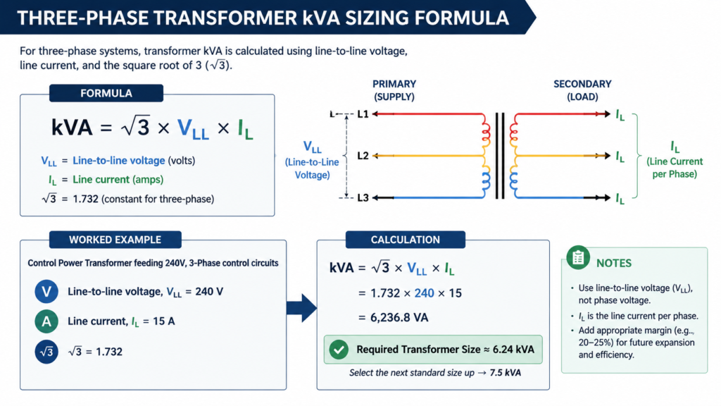
Sizing starts from the load, not from the nameplate of the machine. For three-phase circuits the correct relationship is:
kVA = (line-to-line voltage × full-load current × 1.732) / 1000
The factor 1.732 (√3) appears because in a balanced three-phase system the phase voltages and currents are not all at their peak at the same instant, so apparent power is higher than the single-phase product of voltage and current.
Step-by-step sizing process
Inventory the loads. List every device fed from the secondary: contactors, solenoids, relay coils, indicators, PLC or instrument supplies, heaters, and any small motors or valve actuators.
Sum the VA per phase. Add the sealed (holding) VA of each device per phase to get the steady-state demand.
Add the inrush allowance. Identify devices that energize simultaneously at power-up. The inrush VA of a contactor coil can be several times its sealed VA, and a transformer must supply the worst-case moment without collapsing its output voltage.
Apply a demand factor. If not all loads run at once, apply a realistic utilization factor; if in doubt, oversize rather than undersize.
Select the next standard rating. Choose the next standard kVA size above the calculated value so the unit runs below full thermal stress.
Check regulation and environment. Confirm the expected secondary voltage at full load meets your control devices’ tolerance, and derate for high ambient temperature inside the cabinet.
Load-type guidance
Load type
Sizing note
Contactor and solenoid coils
Size for simultaneous inrush VA; sealed VA alone under-sizes the unit
Resistive heaters and lamps
Straight VA sum, no inrush allowance beyond cold-filament lamps
Small motors and actuators
Keep motor starting load within roughly 60% of rated capacity as a general practice
Electronics (PLC, instruments)
Add 20–25% margin and check for harmonic content in the load
Mixed panel
Sum by phase, balance the phases, then apply the worst-case inrush step
If the terminology around VA, inrush and voltage regulation is new to your team, our control transformer VA rating guide explains each term with worked examples you can adapt to a three-phase calculation.
Wiring Configurations and Standards
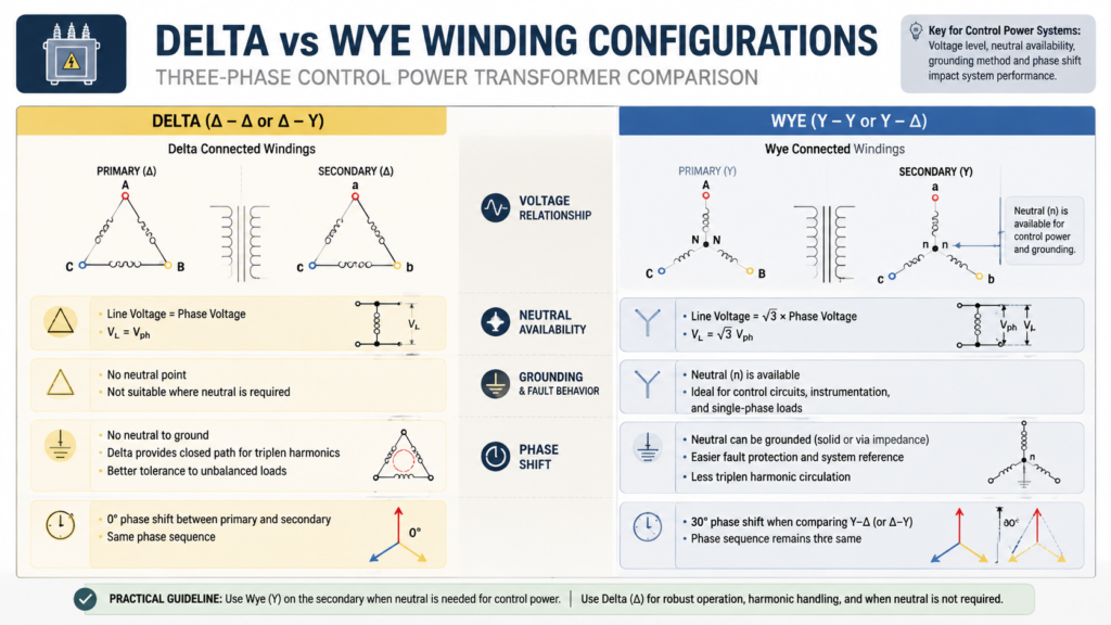
The most common arrangement for control and small power transformers is a delta-connected primary with a wye (star) secondary, designated Dyn11 or Dyn1 depending on the phase shift. A wye secondary provides a neutral point, which is useful when the control loop needs both 3 × 220 V and a 220 V phase-to-neutral supply. Yyn0 configurations, where both sides are wye, are also used when a neutral is required on the primary side.
Frequency and tolerance matter as much as voltage. A unit rated for 50/60 Hz operation is safe on either network, while a 50 Hz-only winding run at 60 Hz will typically have higher core loss. Confirm the available taps (commonly ±5%) so field voltage variations can be corrected at installation.
For compliance, look for products built and tested against the standards family that applies to your destination market: the IEC 61558 series and the UL 5085 series for low-voltage transformers, CSA C22.2 for Canada, and CE marking with RoHS compliance for the European Union. Ask the supplier for the actual test certificates (ratio, no-load loss, dielectric withstand and temperature-rise reports) rather than accepting a marketing claim.
Selection Checklist and Buying Considerations
When you shortlist suppliers, walk through this checklist:
Define the exact primary and secondary configurations, including vector group and whether a neutral is required.
State frequency (50, 60 or 50/60 Hz) and confirm tap positions and tolerance.
Give the load inventory and the worst-case simultaneous inrush so the supplier can verify the kVA selection.
Confirm insulation class, temperature rise and the maximum ambient temperature inside the enclosure.
Specify the certifications your market requires and request routine test reports with each batch.
Check mechanical fit: mounting dimensions, terminal type, finger-safe covers and clearance for cable entry.
Ask about copper windings, batch testing and the manufacturer’s warranty and lead time for OEM quantities.
For single-phase control loads on the same machines — which most panels also contain — the BK series control transformer (50–2500 VA), the JBK3 machine-control series and the BKJ5 series cover the most common 110 V, 220 V and 24 V control circuits. If your project needs a three-phase configuration, specify the vector group and kVA and confirm the build with the manufacturer before ordering; standard and customized units follow the same factory test routine.
Conclusion
A three-phase control power transformer is a small but critical part of any three-phase machine or panel: it supplies the control loop reliably, isolates operators from the line, and absorbs the inrush of coils and actuators that would otherwise drag the supply down. Size it from the real load inventory using the √3 kVA formula, add inrush and environmental margin, and verify the vector group, frequency and certifications before purchase. If you are unsure whether your application needs a single-phase or three-phase unit, or want help confirming a kVA calculation, talk to our engineering team with your load list and supply voltage and we will recommend a configuration that fits.
FAQ
What is a three phase control power transformer used for?
It supplies low-voltage control and auxiliary circuits — contactors, solenoids, relays, PLC and instrument supplies — from a three-phase line such as 380 V or 480 V, while isolating the control loop from the main supply.
How do I calculate the size of a three phase control power transformer?
Use the three-phase apparent power formula: kVA = (line-to-line voltage × current × 1.732) / 1000. Size for the steady-state VA plus the worst-case simultaneous inrush of coils and actuators, then select the next standard rating above the result.
What is the difference between a control transformer and an isolation transformer?
A control transformer is optimized for the inrush of electromagnetic control devices and tight secondary voltage regulation, while an isolation transformer focuses on galvanic separation and noise attenuation. Many control transformers provide isolation as a secondary benefit. See our control transformer vs isolation transformer comparison for the full breakdown.
Can I use a three phase control transformer on a single-phase supply?
Technically one or two windings can be energized from a single-phase feed, but the usable output drops to a fraction of the nameplate rating and the remaining windings can overheat under load. If your supply is single-phase, choose a single-phase control transformer instead.
What input voltages do three phase control power transformers accept?
Typical primaries cover 208 V, 230 V, 380 V, 400 V, 415 V and 480 V at 50 or 60 Hz, often with ±5% taps. Confirm the exact vector group, frequency and tap range on the datasheet for the unit you plan to buy.
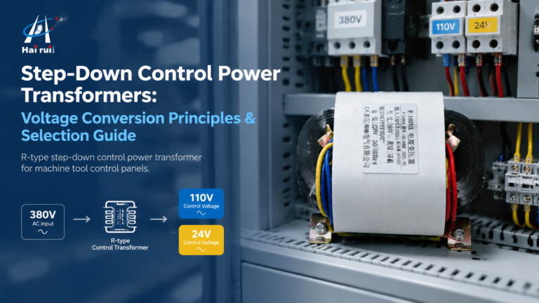
How step-down control power transformers convert 380V/480V line voltage to 110V or 24V control power: turns ratio, VA sizing with inrush, voltage-drop behaviour, wiring and selection.
Practical B2B guide to evaluating machine tool transformer suppliers: certifications, manufacturing depth, product range, batch testing, red flags, and total cost of ownership comparison.