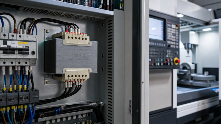
Step-Down Control Power Transformers: Voltage Conversion Principles & Selection Guide
Published: Author: Lisa
A step-down control power transformer converts a higher incoming line voltage — 380 V, 400 V, or 480 V three-phase mains, for example — into the lower control voltage your panel actually runs on, typically 110 V or 24 V. It is the quiet component inside every machine-tool cabinet that keeps PLCs, contactor coils, relays, and indicator lamps fed with the exact voltage they were designed for. This guide explains the voltage conversion principle behind these transformers, the turns-ratio and VA math that governs sizing, and how to select the right unit for a control circuit that will not sag, overheat, or fail on brownouts.
How a Step-Down Control Transformer Converts Voltage
Voltage conversion in a control transformer is pure electromagnetic induction. A primary winding is connected to the incoming line; a secondary winding is connected to the control load. Both share the same laminated iron core, and the ratio of their turns sets the output voltage.
The turns-ratio rule
The fundamental relationship is Vp / Vs = Np / Ns, where Vp and Vs are the primary and secondary voltages and Np and Ns are the primary and secondary turn counts. If a transformer has 4,000 turns on the primary and 250 turns on the secondary, it steps down 480 V to 30 V at the ratio 16:1. On a typical 380 V-to-220 V machine-tool unit the primary simply has roughly 1.73 times the turns of the secondary.
Auto-transformer vs two-winding design
There are two ways to step voltage down, and the difference matters for safety. An auto-transformer uses a single tapped winding, which makes it cheaper and smaller — but the secondary shares a common conductor with the primary, so it provides no galvanic isolation. A true control transformer such as the R-type control transformer uses two electrically separate windings on one core. The isolation between primary and secondary is what lets you reference the control circuit to earth at a single point and keep high-voltage disturbances away from low-voltage electronics.
Why Control Circuits Use 110 V or 24 V Instead of Line Voltage
Stepping down the control supply is not about the transformer’s convenience — it is about operator safety, component life, and consistent coil performance.
Lower shock risk. 110 V and especially 24 V control circuits are far less hazardous to maintenance staff working inside a live cabinet than 380 V or 480 V.
Standardized components. Contactor coils, relays, timers, and PLC inputs are stocked worldwide in 24 V AC/DC and 110 V AC ratings. Feeding a 110 V coil from a 480 V line would destroy it on the first pull-in.
Stable coil pull-in. A dedicated transformer holds the control bus at a regulated level even while motor-starting current drags the main supply down — the classic reason control circuits have their own transformer instead of a tap off the power bus.
Fault isolation. A short in a control device trips only the control-circuit protection, not the whole machine feeder.
Primary and Secondary Voltage Ratings: What the Nameplate Means
Control transformer nameplates list both sides explicitly, and the format tells you how flexible the unit is. A typical dual-primary unit reads “380 V / 220 V–110 V”, meaning the primary can be jumpered for either 380 V or 220 V input, and the secondary offers 110 V (and often a second tap at 24 V).
Nameplate example
Meaning
Typical use
Primary 220 V, Secondary 110 V
Single fixed ratio, no jumpering
Small single-phase panels fed from a 220 V shop supply
Primary 220/380 V, Secondary 110 V
Two selectable primaries via jumper links
Export machines that must run on either 220 V or 380 V mains
Primary 380 V, Secondary 110 V + 24 V
Dual secondary taps
110 V contactor bus plus a 24 V electronic rail
Primary 480 V, Secondary 120 V
NEMA-market control transformer
North American machine tools feeding 120 V controls
When selecting a unit, always confirm the actual line voltage at the installation site before ordering. A transformer wound for 380 V will run correctly on 400 V (well within tolerance) but will over-excite and overheat if fed 460 V. Multi-tap primary units remove this risk because the installer simply sets the jumper for the measured voltage.
VA Rating: Sizing the Transformer to the Control Load
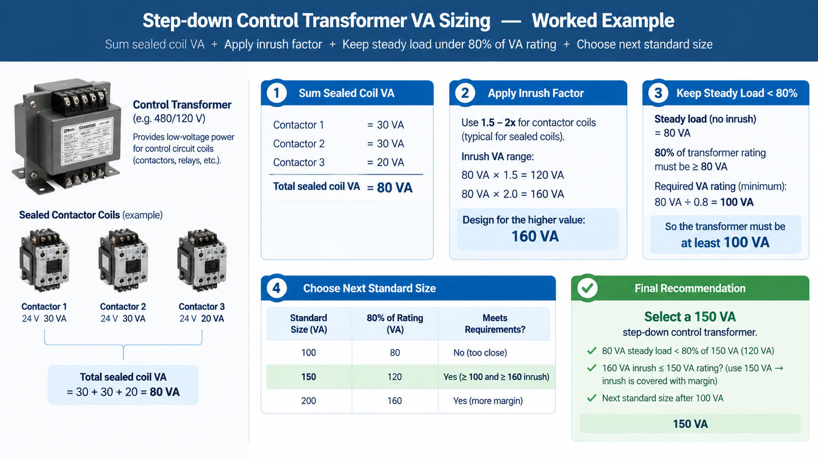
The VA (volt-ampere) rating of a control transformer is the maximum apparent power it can deliver continuously without exceeding its temperature rise. Sizing is not the same as summing nameplate watts, because contactor coils draw a large inrush on pull-in that then settles to a much lower holding power.
Step 1 — sum the sealed (holding) load
Add the steady-state VA of every device on the control bus: each coil’s sealed VA, each relay, each PLC power supply input, each lamp. This is the continuous load the transformer must carry.
Step 2 — add the inrush allowance
When all coils energise together (for example, a bank of contactors closing on machine start), the momentary demand can be 5 to 10 times the sealed VA. If the transformer is too small, the voltage collapses, coils chatter or fail to pull in, and contacts weld. The common practice is to size so that the sum of simultaneous inrush VA stays below the transformer’s rated inrush capability, typically by choosing a unit whose VA rating is 1.5 to 2 times the sealed load when energisation is staggered — or larger when many coils close at once.
Step 3 — verify with the 80 % rule
A robust field rule is to keep the steady-state control load at or below 80 % of the transformer’s VA rating. That margin absorbs measurement error, future additions, and the voltage dip that occurs while the main motor accelerates. A worked example: a panel with four 110 V contactor coils at 8 VA sealed each plus a 10 VA relay equals 42 VA sealed; multiply by a 1.5–2 inrush factor to about 63–84 VA, then pick the next standard size up — a 100 VA unit. For larger multi-coil machines our VA rating guide walks through the calculation step by step.
Voltage Drop Under Load: Why Output Can Sit Below Nameplate
A step-down control transformer is not a regulated supply. Its output voltage depends on load current and on the regulation figure of the unit. Under the inrush of a closing contactor, output can sag noticeably; under continuous sealed load, a well-sized transformer holds output within roughly 3–5 % of nameplate at full rated VA. If your panel’s coils are sluggish or your PLC browns out when the machine starts, check the transformer’s actual loaded output with a true-RMS meter before suspecting the components — the fix is usually a larger VA unit, not a replacement coil.
Primary-side fusing also affects delivered voltage: an undersized or slow primary fuse adds impedance and drop. Match the primary fuse to the transformer’s inrush curve, typically 125–150 % of rated primary current, and fuse the secondary separately for the control load.
Single-Phase vs Three-Phase Step-Down Control Transformers
Control circuits are almost always single-phase, but the supply feeding the transformer may be single-phase or line-to-line three-phase, and that choice changes the unit you buy.
Single-phase step-down (one primary winding, one secondary) is the default for most control panels: 220 V → 110 V or 380 V single-phase → 110 V. Small and inexpensive.
Three-phase-fed control transformers take two lines of a three-phase system (e.g., 380 V between L1 and L2) and step down to 110 V. The primary is still a single winding rated for the line-to-line voltage, so it is not a true three-phase transformer — a distinction covered in our single-phase vs three-phase guide.
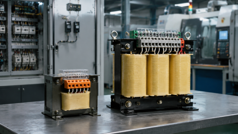
Where a machine has genuinely three-phase control loads — rare in control circuits, more common in auxiliary drives — a three-phase step-down transformer with three matched primary and secondary windings is required, and sizing follows the three-phase kVA formula rather than simple VA summing.
Wiring a Step-Down Control Transformer Correctly
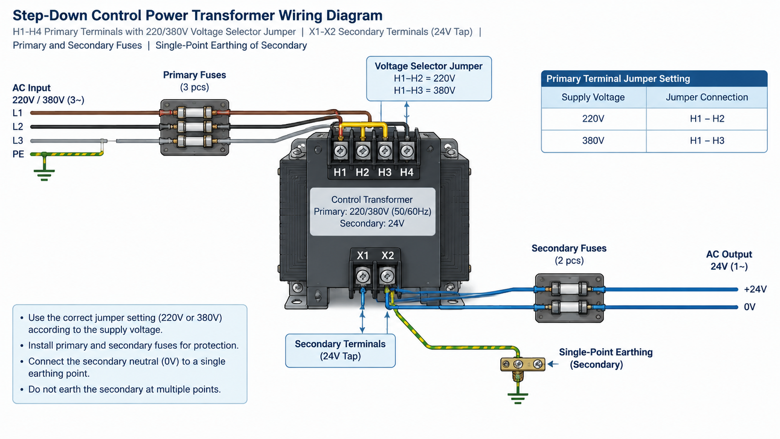
Terminals are standardised on control transformers: primary terminals are marked H1–H4 (or P1–P2 for single-tap units) and secondary terminals are marked X1–X2 (sometimes X1–X3 with a 24 V tap between X2 and X3).
Set the primary jumper for the measured line voltage before connecting anything. Wrong tap = over-excitation or undervoltage.
Connect the line to the primary terminals through a properly sized primary fuse or breaker with a disconnect ahead of it.
Bond the secondary correctly. Ground one side of the 110 V control circuit (X2) at a single point to keep the control bus referenced and make ground-fault detection possible. Do not bond both sides.
Fuse the secondary at a rating sized for the control load, protecting the downstream wiring and devices.
Torque all terminals to the manufacturer’s specification — loose control-wiring connections are a leading cause of intermittent panel faults.
Selecting a Step-Down Control Power Transformer: Checklist
Bring the full picture to a purchase decision:
Input voltage — measured line voltage at the site, with taps for export flexibility.
Output voltage — the control bus voltage: 110 V for coil-heavy panels, 24 V for electronic loads, or both from a dual-tap secondary.
VA size — sealed load × inrush factor, keeping steady load ≤ 80 % of rating.
Insulation class — Class B or F insulation for cabinet heat; check ambient temperature rating.
Enclosure and mounting — foot-mount, DIN rail, or panel mount; finger-safe terminals for open installations.
Certifications — CE, RoHS, and IEC/EN 61558 compliance for the target market; UL/CSA listed for North America.
The R-type series, plus the BK and JBK3 series across the control transformer range, cover 220/380 V inputs with 110 V and 24 V secondaries from 50 VA to 2,500 VA — a fit for most machine-tool and panel-building applications. If your machine ships to multiple regions, choose a dual-primary (220/380 V) unit so the same transformer stock serves both markets.
Conclusion
A step-down control power transformer converts line voltage to a safe, stable control bus using the turns-ratio principle, and the whole art of selection is in three numbers: the input voltage, the output voltage, and the VA rating sized for coil inrush as well as sealed load. Get the ratio right and the transformer is invisible — a component you never think about again. Get it wrong and you will chase chattering coils, brown-out resets, and burned-out devices for months. Measure the line, count the coils, apply the 80 % rule, and choose a unit with the taps, isolation, and certification your application needs.
Frequently Asked Questions
What is a step-down control power transformer used for?
It reduces the incoming line voltage (such as 380 V or 480 V) to a lower control voltage (typically 110 V or 24 V) to power contactor coils, relays, PLCs, and indicator lamps in industrial control panels.
How do I calculate the output voltage of a step-down transformer?
Use the turns ratio: Vs = Vp × (Ns / Np). For practical purposes read the secondary nameplate rating, which states the output voltage at the rated input and full load.
Can a 380 V primary transformer run on 220 V?
Not safely unless the primary has a 220 V tap. Feeding a 380 V-wound primary with 220 V gives roughly half the rated output voltage; feeding it 480 V over-excites it and causes overheating.
What size control transformer do I need for four contactors?
Sum the sealed VA of all four coils and any other control devices, multiply by 1.5–2 for inrush, and keep the result under 80 % of the transformer VA rating. Typically 100–200 VA covers four standard contactor coils.
Why does my control transformer run hot?
Likely causes: a unit oversized for the load is fine, but an undersized one, wrong primary tap, high ambient cabinet temperature, or a shorted secondary load all cause overheating. Measure the secondary current and compare it with the VA rating.
Do I need a separate transformer for 24 V PLC power?
Often yes for isolation and stability. A dual-tap control transformer providing both 110 V and 24 V secondaries can serve coil circuits and electronics from one unit, but check the 24 V tap’s current capacity against the PLC supply demand.
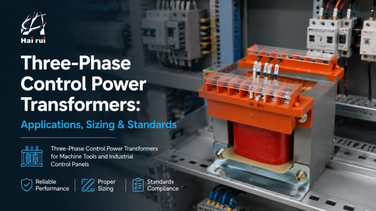
How three-phase control power transformers work, how to size them for machine tool and control-panel loads, and the delta/wye, standards and protection choices that matter in the field.
Practical B2B guide to evaluating machine tool transformer suppliers: certifications, manufacturing depth, product range, batch testing, red flags, and total cost of ownership comparison.