Offshore Wind 66 kV Collection Systems: Breaker Selection for Salt Spray and Vibration
How 66 kV changed the collection system, what C5-M salt spray demands in measurable terms, and why the breaker boundary runs along the shoreline.
Read More
An out of phase switching circuit breaker duty is the condition where the breaker makes or breaks current with the two sides of the circuit out of synchronism — up to 180 electrical degrees apart — and it is one of the two ratings that most purchase specifications quietly leave out. The other is the close-open duty: closing onto a live fault and being required to open again immediately, with no pause to recover. Both are defined in IEC 62271-100, both are tested, and both are routinely dropped from a datasheet because the buyer assumed the short-circuit rating covered them. It does not. A breaker that passed T100a at 40 kA has proved it can interrupt a bolted fault at its own terminals; it has proved nothing about interrupting 20 kA between two systems that have drifted apart, or about surviving a close onto a fault already established before the contacts touch.
This article sets out what each duty physically is, what the standard numbers mean, why half the current can be the harder job, and what belongs in the datasheet if you want the capability rather than the assumption. If you are comparing high-voltage SF6 circuit breakers for a tie line, a busbar section or a generator circuit, these are the two line items worth adding before the enquiry goes out.
Two parts of a network that are connected through a breaker normally run at the same frequency and a small phase angle. Loss of a line, a generator trip or a system split can leave the two sides drifting. The angle opens up, and at some point a breaker is called on to operate across that angle — either to clear the split or, more dangerously, to close and re-establish the connection while the angle is still large.
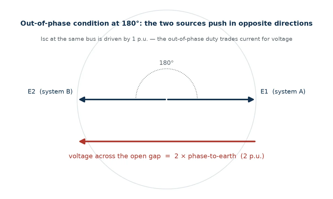
At 180 degrees the two source voltages oppose each other. The voltage driving current through the breaker is not one phase-to-earth voltage but twice that, because the two systems push in opposite directions. This is the whole basis of the duty: the current is modest compared with a terminal fault, but the voltage the interrupter has to withstand immediately after current zero is doubled.
It is worth separating two situations that get conflated. Breaking out of phase means the breaker opens across a live angle — the current is a load-transfer current, roughly symmetrical, and the stress is dielectric rather than thermal. Making out of phase means closing across the angle, which produces a fully offset current and a mechanical and thermal shock. IEC 62271-100 rates these together as a single out-of-phase making and breaking current, which is convenient for the standard and slightly misleading for the buyer: the two halves stress different parts of the breaker.
The standard offers two levels, and the choice between them is a system study question, not a commercial one. OP1 is 25 percent of the rated short-circuit breaking current; OP2 is 50 percent. Both are tested with a recovery voltage of twice the rated phase-to-earth voltage, which for a 126 kV breaker means the gap must withstand roughly 1.15 times the rated line-to-line voltage in the first instants after interruption — against a normal terminal fault where the first-pole-to-clear factor for an effectively earthed system is 1.3 times phase-to-earth.
| Parameter | Terminal fault (T100a) | Out-of-phase OP1 | Out-of-phase OP2 |
|---|---|---|---|
| Breaking current | 100% of rated Isc | 25% of rated Isc | 50% of rated Isc |
| Recovery voltage | 1.0 p.u. of phase-to-earth | 2.0 p.u. | 2.0 p.u. |
| Current × voltage, relative | 1.00 | 0.50 | 1.00 |
| Dominant stress | Arc energy, pressure, contact erosion | Dielectric recovery | Dielectric recovery with a hot gap |
| Typical system condition | Fault at the breaker terminals | Angle opening on a weak interconnection | Strong tie, or closing across a large angle |
A note on a number that circulates in procurement documents: the 2.5 factor belongs to peak withstand current — 2.5 times the rated short-time withstand current at 50 Hz, 2.6 at 60 Hz — and not to out-of-phase duty. The out-of-phase figures are the 25 percent and 50 percent currents at 2 p.u. voltage. When the two are written into a single line item as “2.5 times the short-circuit current”, the resulting requirement is not something a test laboratory can perform, and the enquiry tends to come back with a polite request for clarification rather than a price.
The instinct is to read OP2 as a 50 percent duty and therefore an easy one. The table above shows why that reading fails: at half the current and twice the voltage, the volt-ampere product of the duty is essentially the terminal-fault value. The interrupter is being asked to hold off twice its normal voltage with a gap that has just carried a real arc, and it is being asked to do so at a moment when the gas in the nozzle is hot and ionised rather than cool and dense.
The physics is straightforward once the numbers are laid out. Arc voltage in an SF6 interrupter is roughly constant with current, so arc energy scales with current and arcing time — which means OP2 deposits about half the thermal energy of a T100a duty. That is genuinely easier on the contacts. But thermal reignition is only one of the two ways an interrupter fails. The other is dielectric, and the dielectric stress after current zero has doubled. A design with generous thermal margin and a thin dielectric margin passes T100a and fails OP2, which is exactly why the standard tests them separately rather than assuming one covers the other.
There is also a system-side implication hidden in the 50 percent figure. With two systems at 180 degrees, the current is the doubled voltage divided by the sum of the two source impedances. Setting that equal to half the rated short-circuit current implies the two source impedances sum to roughly four times the impedance behind the rated short-circuit level — each side about twice as weak as the busbar fault level. That is reasonable for a long tie between two moderate systems. It is a poor assumption for a busbar section breaker in a strong station, where both sides may be stiff and the actual out-of-phase current can climb toward the full terminal-fault value. In that case OP2 as written is not conservative, and the specification should say so.
Close-open is the second rating that goes missing. The condition is simple to describe and brutal in practice: the breaker receives a close command into a circuit that is already faulted. The contacts touch, the fault current establishes, and the protection trips within tens of milliseconds. The breaker must open immediately — and it must do so whether or not the close command is still being held, which is what trip-free means.
Two damage mechanisms act at once, and they are worth separating because they wear different parts of the machine.
The first is pre-arcing on closing. Contacts do not touch at the instant the mechanism decides they should; the gap breaks down dielectrically first, and the arc burns across the closing gap for a few milliseconds at full fault current. In that window the puffer has not yet compressed and the self-blast chamber has not yet been heated, so the arc runs with almost no gas blast to cool it. Erosion per millisecond in pre-arcing is far higher than in a normal opening operation. This is why a breaker rated for 3000 mechanical operations may be rated for a small fraction of that at rated current, and why closing operations at fault level are the ones that consume contact life.
The second is opening from a standing start. In a normal opening operation the mechanism begins from a settled closed position with the opening spring fully charged. In a close-open sequence the opening has to begin while the mechanism is still absorbing the closing impact, the latch must release under a load that has not yet come to rest, and the opening spring has just done work that it now has to repeat. Damping, bounce and latch timing all matter more here than in the sequence the breaker spends most of its life performing.
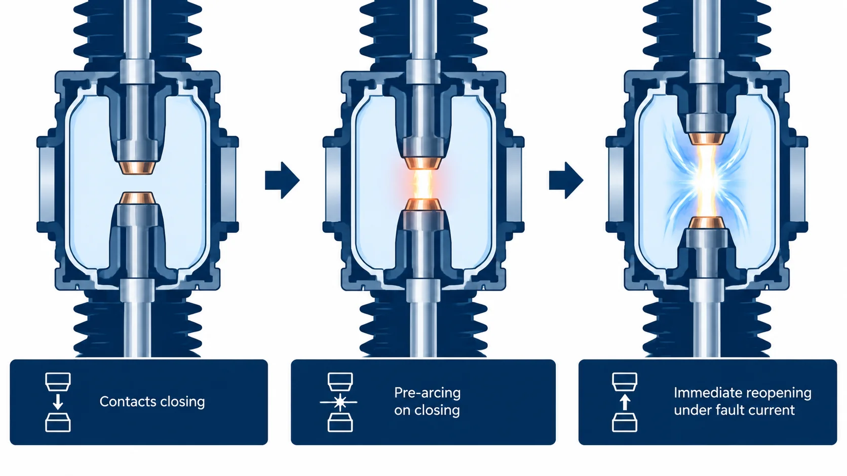
The standard defines the sequences rather than a single figure, and the sequence is what the type test report should show evidence for. The rated operating sequence for a transmission breaker is normally O – 0.3 s – CO – 3 min – CO at rated short-circuit breaking current; auto-reclosing schemes add their own dead times on top of that.
| Sequence | What it represents | What it proves |
|---|---|---|
| O | Single opening at rated Isc | Basic breaking capability with a fully charged mechanism |
| CO | Close onto a fault, then open without delay | Pre-arcing tolerance and opening from a standing start |
| O – 0.3 s – CO – 3 min – CO | Rated operating sequence | Full duty cycle including spring recharge and damping recovery |
| O – t – CO – t’ – CO | Auto-reclosing, t typically 0.3 s to 1 s, t’ the reclaim time | Repeated reclose duty and reclaim time for the drive |
| CO with the close command held | Trip-free and anti-pumping check | Opening is not blocked by a maintained close signal |
The close-open time — contact touch to contact part — is a declared characteristic, typically 40 ms to 70 ms for transmission-class breakers. It sets the floor on how fast a reclose can be attempted, and it is the window in which the interrupter absorbs pre-arcing plus a full opening arc back to back.
Both duties are easy to dismiss as theoretical until you map them onto a single-line diagram. The conditions that generate them are specific and recognisable.
Tie lines and interconnectors are the classic out-of-phase case. Two systems connected by one line will separate under disturbance, and the angle across the tie is exactly the quantity that decides whether the interconnection holds. Breakers at both ends need OP1 or OP2 declared, and the angle the protection trips at should be consistent with the rating. A scheme that trips at 60 degrees into a breaker rated for OP1 at 180 degrees is fine; one that trips at 170 degrees into the same breaker is relying on a duty that was never tested.
Busbar section and bus coupler breakers sit between two busbars that may be fed from different sources and may be at different angles during switching or after a split. These are the cases where the “two weak systems” assumption behind OP2 breaks down, because both sides can be strong. This is the application where the split-type arrangement of a large breaker earns its cost — a 252 kV unit with independent pole enclosures and generous phase spacing has more room to absorb the recovery voltage than a compact three-phase-in-one-tank design. The LW-252 4000 A split-type breaker is the sort of unit specified where the busbar section duty is real rather than nominal.
Line breakers with auto-reclosing are the home of the close-open duty. Every reclose attempt after a trip is a close into a circuit whose condition is unknown. Most of the time the fault has cleared and the breaker closes into a healthy line; occasionally it has not, and the breaker performs the duty it was bought for. This is the link between the two ratings and the reason the auto-reclosing sequence deserves to be specified alongside the breaking current rather than treated as a protection detail.
Synch-check closing adds a third layer. Where a breaker is permitted to close only within a window, the window itself is a statement about the out-of-phase making duty the breaker can absorb. A 20-degree window and a 180-degree rating are not the same specification, and only one of them is testable.
The reason these ratings go missing is that neither is a single number a buyer can compare across vendors. Both are compound statements, and if the specification asks for less than the compound statement, the answer will be whatever the vendor finds convenient. The table below is the minimum that makes the requirement testable.
| Item | What to write | Why it matters |
|---|---|---|
| Out-of-phase level | OP1 or OP2, and the percentage of rated Isc | “Suitable for out-of-phase switching” without a level is unverifiable |
| Recovery voltage basis | 2 p.u. of rated phase-to-earth | Distinguishes a real OP test from a reduced-voltage approximation |
| Type test evidence | Report reference for OP1/OP2 at the declared level | A terminal-fault report is not evidence for this duty |
| Rated operating sequence | O – 0.3 s – CO – 3 min – CO, or the project sequence | Sets the mechanism energy and damping requirement |
| Close-open time | Declared value in milliseconds | Bounds the pre-arcing plus reopening exposure |
| Trip-free and anti-pumping | Stated explicitly as required functions | Safety function, not a feature to be traded away |
| Mechanical and electrical endurance | Class per IEC 62271-100, with the current basis | Connects contact life to the number of fault closings expected |
| Angle basis for protection | The angle at which the scheme trips, cross-checked to the rating | Prevents a protection setting that outruns the breaker |
The single most useful discipline here is to make the protection engineer and the breaker specification agree on the same angle. Most out-of-phase incidents that damage equipment are not failures of the breaker; they are cases where the protection was set to operate at an angle the breaker was never rated for, because nobody put the two documents side by side.
Not every project needs OP2, and paying for it where the system cannot produce the condition is waste. A radially fed substation with a single incoming source has no mechanism for a 180-degree angle across its breakers — the two sides cannot drift apart because there is nothing to drift against. The test is whether the breaker can ever separate two live sources. If it can, the rating is real; if it cannot, the rating is decoration. The grey zone is the network with a normally open point: radial today, looped after a reconfiguration, and the breaker that was adequate quietly becomes the weak link. Specifying OP1 wherever the topology could plausibly close is cheap insurance.
The close-open duty has no equivalent escape clause. Any breaker that can be closed by a human or by an auto-reclose scheme can be closed onto a fault, and over twenty years the probability is not negligible. CO is always applicable; the only real question is how many times the project expects to use it, which is what the endurance class answers.
Neither rating stands alone, and the interactions are where specifications get into trouble. Out-of-phase breaking is a dielectric duty, so it leans on the same insulation coordination that governs the 126 kV industrial grid breaker family’s lightning impulse and power-frequency withstand levels — a breaker with a thin insulation margin will show it here first. Close-open is a thermal and mechanical duty, so it leans on the short-time withstand rating and the mechanism’s endurance class rather than on the interrupter’s dielectric design.
That split is useful when reading a standards comparison and working out which declared values are relevant to your application. It is also why a breaker can look excellent on the headline ratings and still be the wrong choice: 40 kA breaking capacity and a 40 kA/3 s short-time withstand say nothing about whether the unit will hold 2 p.u. across a hot gap, or how much contact life one close-onto-fault consumes.
For the arithmetic behind the current side of these duties — how much asymmetry a breaker is actually tested against, and why T100a is the harder of the two 100 percent duties — the companion piece on breaking-capacity test duties works through the numbers. The two articles are deliberately adjacent: one is about the voltage the breaker must hold, the other about the current it must interrupt, and a specification that gets only one of them right is half a specification.
No. Short-circuit breaking is tested at the rated breaking current with a recovery voltage of one per unit of phase-to-earth voltage. Out-of-phase switching is tested at 25 or 50 percent of that current with a recovery voltage of two per unit. The current is lower and the voltage is higher, and a breaker can pass one and fail the other because the two duties stress different margins.
Close-open is the duty — closing onto a fault and opening immediately. Auto-reclosing is a scheme that performs it, usually after a dead time that lets a transient fault clear. The breaker’s CO capability is the same in both cases; what changes is how often the duty is expected and what dead time the mechanism has to recover within.
Not automatically. T100a is the thermal worst case and OP2 is close to the dielectric worst case. A design with strong arc control and modest insulation margin passes the first and can fail the second, which is precisely why the standard defines both duties and why a type test report for one is not evidence for the other.
Because of pre-arcing. During closing the gap breaks down before the contacts touch, and for those few milliseconds the arc runs with no puffer pressure and no self-blast heating, so the arc is not being cooled or constricted. The energy per millisecond is far higher than in a controlled opening, and the same contacts then have to interrupt the fault current immediately afterwards.
For the out-of-phase duty, the report reference showing OP1 or OP2 at the declared level with the 2 p.u. recovery voltage. For close-open, the sequence tested, the close-open time achieved and the number of CO operations in the endurance programme. If a vendor cannot point to a report for the specific duty, the rating on the datasheet is a design intention rather than a verified characteristic.
Out-of-phase and close-open decide whether a breaker survives the conditions it will actually meet, and they are the two ratings that most often fail to make it from the standard into the purchase order. The first is about holding twice the normal voltage across a gap that has just carried an arc; the second about pre-arcing into a fault and then opening from a standing start. Neither is covered by the short-circuit rating.
If the project has a tie line, a busbar section or an auto-reclose scheme — which is most transmission projects — both belong in the specification with a level and a test report reference attached. Our SF6 circuit breaker technical library covers the surrounding duties, and the engineering team can walk through the OP and CO requirement for a specific single-line diagram if you send it across with the fault levels.