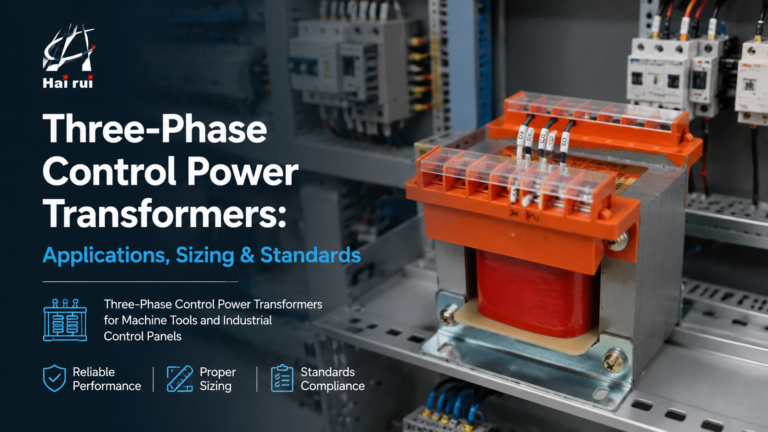
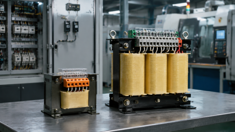
What Is the Purpose of a Standard Control Transformer?
Published: Author: Lisa
Walk past almost any industrial control cabinet and you will find the same small
device doing an important job: the standard control transformer. Its purpose is easy
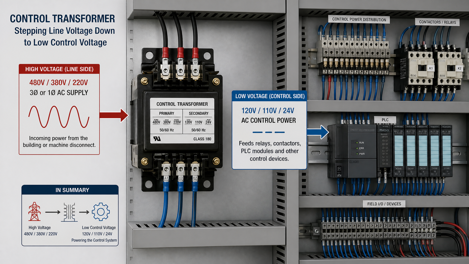
to state but easy to overlook — it takes the higher line voltage and steps it down to
a low, safe, and stable control voltage for the relays, contactors, and PLC modules
that actually run the machine. This guide from
Hairui Electric explains the
purpose of a standard control transformer,
how it differs from a power transformer, what it feeds, and how to size one correctly.
What Is a Standard Control Transformer?
A standard control transformer — often called a control power transformer (CPT) — is
a step-down transformer built specifically for control circuits rather than for
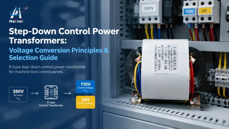
delivering bulk power. It converts a higher supply voltage, commonly 480 V,
380 V, or 220 V, into a low control voltage, most often 120 V,
110 V, or 24 V. The output then feeds the “brains” of the
machine: the coils, timers, lamps, and logic that switch the real power on and off.
The Core Purpose: Step Down, Isolate, and Stabilize
The purpose of a standard control transformer can be broken into three jobs it
performs at the same time.
Step Down the Voltage
Control components are not built to sit directly on a 480 V or 380 V line.
A control transformer uses the turns ratio of its windings to bring that voltage down
to a level that relays, contactors, and PLC inputs are designed to handle safely.
Isolate the Control Circuit
Because the primary and secondary windings are magnetically coupled rather than
electrically connected, the control circuit is isolated from the power line. This
keeps line-side faults and surges away from sensitive electronics and lets the control
circuit be grounded independently for safer maintenance.
Provide Stable Control Power
Contactors and solenoids draw a large burst of current when they first pull in. A
standard control transformer is designed with lower internal impedance than a
comparable power transformer, so the control voltage stays steady during that brief
inrush instead of sagging and dropping out other coils already on the circuit.
What a Standard Control Transformer Powers
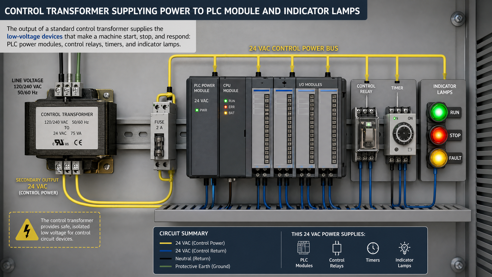
The output of a standard control transformer supplies the low-voltage devices that
make a machine start, stop, and respond correctly:
Contactor coils and motor starter coils
Control relays and timers
PLC power modules and inputs
Indicator lamps, pilot lights, and buzzers
Solenoids and work-lamp circuits
A good example is the
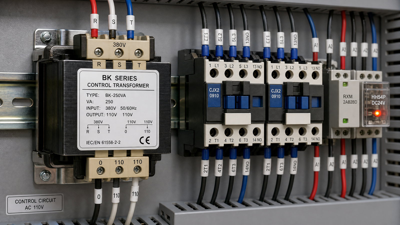
BK Series Control Transformer,
a general-purpose control transformer rated from 50 VA to 2500 VA with
220 V or 380 V input and 6 V to 220 V output. It is a common
choice for machine tools and automation panels that need one dependable control
supply for all of these loads.
Standard Control Transformer vs Power Transformer
The two look similar, but they are built and rated for different jobs. The table below
summarizes the main differences.
Characteristic
Standard control transformer
Power transformer
Main job
Feed low-voltage control circuits
Deliver bulk power to equipment
Rating unit
Volt-amperes (VA)
kVA or MVA
Load type
Intermittent, inrush-heavy coils
Continuous, steady load
Key design goal
Tight voltage regulation under inrush
High efficiency at full load
Why Inrush and VA Matter
A control transformer is sized in volt-amperes, not watts, because its loads are
coils that draw more than their steady-state power. When a contactor coil energizes,
it can draw several times its “sealed” current for a fraction of a second.
The transformer must deliver this inrush without letting the secondary voltage dip
far enough to drop out other contactors. That is why the inrush VA of the largest
coil is often the deciding number in a panel design.
How to Choose and Size One
Sizing a standard control transformer follows a simple four-step process:
Add the sealed VA of every coil and load the transformer will feed.
Add the inrush VA of the single largest coil that energizes at once.
Select a VA rating that covers both, keeping regulation within about 85–90% of rated voltage.
Fuse the secondary so a shorted coil cannot overheat the winding.
Sizing by watts instead of VA, which under-rates the transformer for coil loads.
Ignoring inrush VA, so the control voltage dips and contactors chatter or drop out.
Skipping secondary fusing, leaving a shorted coil to overheat the winding.
Forgetting to derate for high ambient temperature or continuous duty.
Frequently Asked Questions
What is the purpose of a standard control transformer?
It steps the line voltage down to a low control voltage and isolates the control
circuit, providing a stable supply for relays, contactors, PLCs, and pilot devices.
What voltage does a standard control transformer output?
Common secondary voltages are 120 V, 110 V, and 24 V, with many models
offering dual or customizable primaries for 220 V, 380 V, or 480 V.
Is a control transformer the same as a power transformer?
No. A control transformer is built for tight voltage regulation under intermittent,
inrush-heavy control loads and is rated in VA, while a power transformer is built for
continuous bulk power delivery.
Why are control transformers rated in VA instead of watts?
Because their loads are coils that draw reactive current and high inrush, VA better
represents the actual burden the transformer must carry than watts alone.
How do I size a standard control transformer?
Add the sealed VA of all loads plus the inrush VA of the largest coil, then select a
rating that keeps regulation within about 85–90% of rated voltage and fuse the
secondary.
Conclusion
The purpose of a standard control transformer is to give every machine a low, isolated,
and stable control supply it can rely on — the difference between a panel that runs
quietly for years and one that trips the moment a contactor pulls in. For more about
the manufacturer behind this range, see our
about us page, or
contact us for help selecting and
quoting the right control transformer for your application.
How step-down control power transformers convert 380V/480V line voltage to 110V or 24V control power: turns ratio, VA sizing with inrush, voltage-drop behaviour, wiring and selection.
How three-phase control power transformers work, how to size them for machine tool and control-panel loads, and the delta/wye, standards and protection choices that matter in the field.