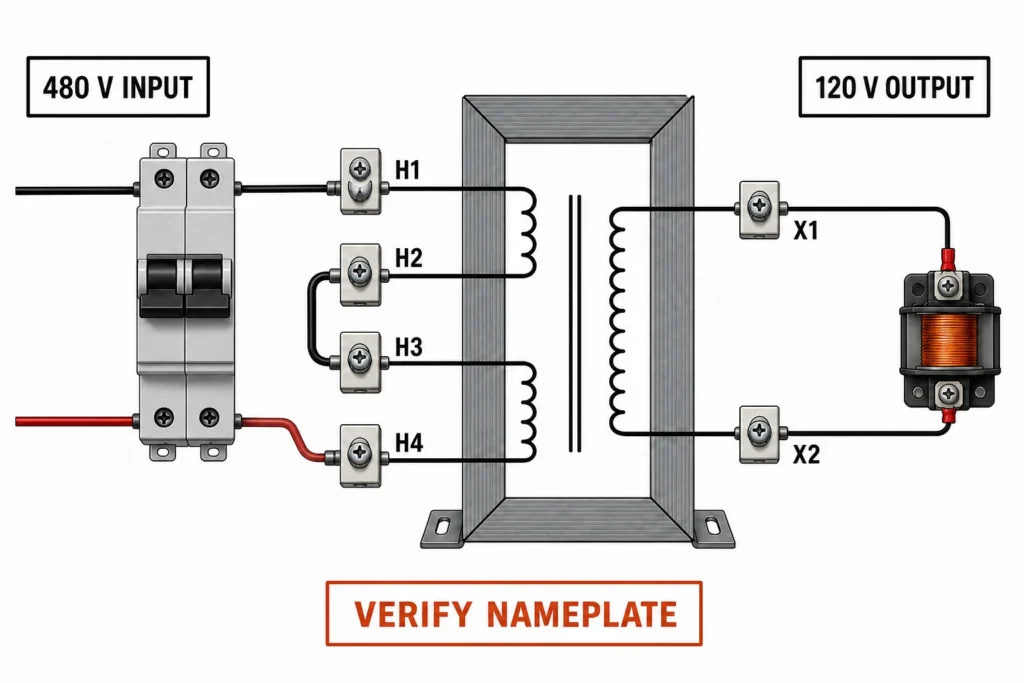
A 480v to 120v control transformer wiring diagram shows how a control transformer takes two 480 V line conductors on its primary side and provides an isolated 120 V AC supply for contactor coils, relays, pilot lights, and other control loads. On a common dual-primary design, the two primary windings are connected in series for 480 V; the secondary is then connected according to the transformer’s nameplate to produce 120 V.
The terminal letters may look simple, but transformer connections are not universal. This guide explains the common H1-H4 and X1-X2 arrangement, protection and grounding considerations, a safe verification sequence, and frequent wiring errors. It is an educational reference for qualified electrical personnel—not a substitute for the diagram supplied with the exact transformer. For a broader view of Hairui Electric’s equipment range, start at the Hairui Home page.
480v to 120v control transformer wiring diagram What Does the Show?
In a typical single-phase control transformer with two 240 V primary windings, the windings are placed in series for a 480 V source. The common connection is:
connect the two 480 V supply conductors through properly selected overcurrent protection to H1 and H4;
join H2 to H3 to place the two primary windings in series;
take the 120 V control output from the secondary terminals specified by the nameplate, often X1 and X2 on a dedicated 120 V secondary;
protect the secondary circuit and establish the required grounded conductor and equipment grounding connections according to the system design and applicable rules.
Do not apply these terminal jumpers by assumption. Some transformers use a single 480 V primary, multiple taps, flying leads, or a 120/240 V dual secondary. The nameplate diagram is the authority for that unit.
How to Read H and X Terminal Markings
North American transformer diagrams commonly use H markings for the higher-voltage winding and X markings for the lower-voltage winding. The numbers identify winding ends and polarity; they do not, by themselves, guarantee a particular voltage.
Marking
Typical meaning
What to verify
H1, H2
Ends of one primary winding or primary circuit
Rated voltage, polarity, and line connection
H3, H4
Ends of a second primary winding on a dual-primary unit
Series or parallel jumper arrangement
X1, X2
Ends of a single secondary winding
Rated output voltage and grounded-conductor treatment
X3, X4
Additional ends on a dual-secondary design
Whether windings must be series- or parallel-connected
Polarity matters when separate windings are joined. An incorrect series connection can make voltages oppose one another; an incorrect parallel connection can create a severe circulating current. Never use resistance readings alone to decide the final phasing of unidentified windings.
Why Two 240 V Primary Windings Are Wired in Series
A common dual-voltage control transformer has two identical 240 V primary windings. In the 480 V configuration, the windings share the applied voltage in series. With H2 joined to H3 and the supply applied across H1 and H4, each winding sees approximately 240 V.
For a 240 V source, the same two windings may instead be connected in parallel, but only with the exact polarity connections shown by the manufacturer. The 240 V configuration is not simply the 480 V circuit with a different supply voltage. Misplacing one jumper can damage the transformer or upstream protection.
The H2-H3 series jumper is common, not universal. Check the terminal diagram, catalog sheet, frequency rating, and measured source voltage before making any connection.
Step-by-Step Planning Sequence
The following sequence is deliberately framed as a planning and verification workflow. Actual installation, energized testing, and code decisions should be handled by qualified personnel using approved procedures.
Identify the source. Confirm that the available supply is 480 V line-to-line at the correct frequency. A 480Y/277 V system provides 480 V between phases; it does not provide 480 V from a phase to neutral.
Read the complete nameplate. Verify primary and secondary voltages, VA rating, frequency, insulation information, terminal arrangement, and the manufacturer’s connection diagram.
Calculate the control load. Add the sealed VA of simultaneous loads and check the inrush VA of contactors and solenoids. A transformer sized only for steady-state VA may suffer excessive voltage drop during pickup.
Select protection and conductors. Size primary and secondary protection and wiring for the transformer, available fault current, control load, and governing electrical rules. Follow manufacturer limitations.
Isolate and verify absence of voltage. Use the approved lockout/tagout process and an adequately rated tester before touching conductors.
Configure the primary from the nameplate. On the common dual-240 V example, this means the series link between H2 and H3, with protected supply conductors to H1 and H4.
Configure the secondary from the nameplate. A dedicated 120 V secondary commonly provides output across X1 and X2. A dual 120 V secondary may require different parallel connections, such as paired winding ends, that must match the exact diagram.
Complete bonding and grounding. Treat the separately derived secondary and equipment grounding path in accordance with the system design and applicable local requirements.
Inspect before energizing. Check terminal torque, conductor identification, clearances, enclosure condition, fuse or breaker ratings, jumper placement, and the absence of stray strands.
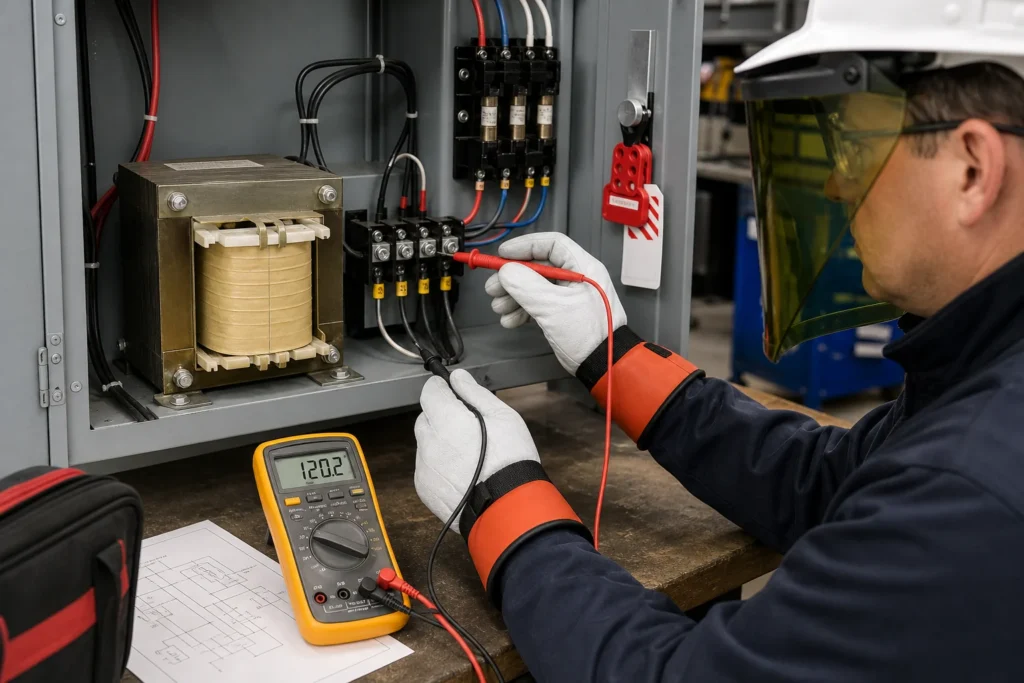
Verify output under controlled conditions. Use properly rated PPE, instruments, and procedures. Confirm secondary voltage before connecting sensitive loads, then check performance when the control load operates.
Primary and Secondary Protection
The primary is connected between two ungrounded conductors of the 480 V system, so disconnecting and overcurrent protection must address that circuit appropriately. The simplified diagram in this article depicts linked two-pole primary protection so both input conductors are controlled together. The final protective-device type and rating depend on transformer inrush, conductor ampacity, available fault current, the equipment listing, and the governing code.
The 120 V secondary also needs a deliberate protection strategy. Many control circuits place protection in the ungrounded secondary conductor, commonly associated with X1 after the grounded side has been established. Some applications require protection of more than one secondary conductor. Do not copy a one-fuse or two-fuse arrangement without evaluating the actual grounding method and rules for the installation.
Protective devices should tolerate normal magnetizing inrush while clearing faults safely. Repeated nuisance opening is not automatically proof that a larger fuse is appropriate; it may indicate incorrect wiring, an undersized transformer, a secondary fault, or an unsuitable protection characteristic.
Grounding and Bonding the 120 V Control Circuit
A transformer’s secondary is electrically isolated from its primary and is typically treated as a separately derived source. One secondary conductor may be intentionally grounded so the control circuit has a defined reference and protective devices can clear certain faults. The equipment grounding conductor is different: it bonds exposed conductive parts and the enclosure to the grounding system.
The exact grounding electrode, bonding jumper, grounded-conductor, and overcurrent-protection requirements vary with jurisdiction, system configuration, transformer rating, and equipment listing. Avoid creating multiple unintended neutral-to-ground connections downstream, and never use an equipment grounding conductor as a normal current-carrying return path.
How the 120 V Secondary Feeds a Motor Control Circuit
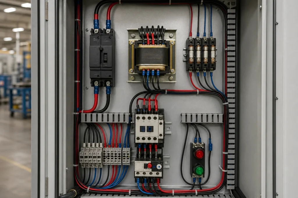
Once the secondary is correctly configured, the ungrounded 120 V control conductor normally passes through its protective device and then through control elements such as a stop button, start button, overload contact, limit switch, or safety relay. The circuit then reaches the contactor coil and returns to the other secondary conductor.
The transformer supplies the control circuit only; it does not reduce the voltage delivered to a 480 V motor. The motor remains on the three-phase power circuit, while the 120 V circuit operates the contactor that connects or disconnects that motor. This separation allows familiar control devices to operate without carrying motor current.
A disciplined inspection can catch many faults before power is applied:
confirm the supply is line-to-line 480 V and matches the nameplate frequency;
verify the primary jumper arrangement against the drawing;
verify any dual-secondary series or parallel links against the drawing;
check that protection is installed in the intended conductors;
confirm enclosure bonding and the planned secondary grounding point;
inspect conductor insulation, ferrules or lugs, clearances, and terminal torque;
disconnect or isolate sensitive loads for the initial output check when the manufacturer’s procedure calls for it.
After energization under an approved safe-work procedure, measure the secondary at the designated terminals. A reading near 120 V at no load is only one check. Excessive voltage drop when a contactor picks up can point to an undersized transformer, excessive conductor drop, poor terminations, or a problem in the control device.
Common Wiring Mistakes and Symptoms
Mistake
Possible result
What to check
Primary windings configured in parallel on 480 V
Immediate damage or operation of protection
Nameplate series connection and jumper placement
Incorrect polarity when joining windings
Near-zero output, circulating current, or overheating
Manufacturer’s terminal diagram
480 V taken from phase to neutral on a 480Y/277 V system
Only about 277 V applied to the primary
Source conductors and measured line-to-line voltage
Secondary grounded at multiple unintended points
Objectionable current or confusing fault paths
Bonding and grounded-conductor layout
Transformer sized only by sealed VA
Contactor chatter or secondary voltage sag
Simultaneous inrush VA and regulation data
Protection increased after nuisance opening
Reduced fault protection
Wiring faults, inrush characteristics, and approved ratings
Choosing the Right 480 V to 120 V Control Transformer
Electrical compatibility starts with the voltage combination, but it does not end there. Confirm continuous VA, inrush capability, frequency, temperature rise, insulation class, open or enclosed construction, terminal accessibility, mounting dimensions, ambient conditions, and required standards. The Catalog can help you compare product families, while the About Us page provides background on Hairui Electric manufacturing capabilities.
For a quotation or engineering discussion, provide the available primary voltage and frequency, desired secondary voltage, sealed and inrush VA, load types, enclosure requirement, ambient conditions, mounting limits, destination market, and quantity. These details prevent a generic voltage match from becoming an unsuitable panel component.
The common 480 V-to-120 V control-transformer arrangement uses two primary windings in series and an isolated 120 V secondary, but terminal layouts and grounding methods vary. Start with the nameplate, size for both sealed and inrush VA, protect the primary and secondary correctly, and verify the completed system using approved safety procedures. To match a transformer to a specific panel, send the full electrical and mechanical requirements through the Contact Us page.
Frequently Asked Questions
Can I connect a control transformer directly between two phases of a 480 V three-phase system?
A correctly rated single-phase control transformer is commonly connected line-to-line between two phases, subject to the manufacturer’s instructions, circuit protection, system design, and applicable rules. It does not require all three phases.
Why are H2 and H3 connected together?
On a common transformer with two 240 V primary windings, that link places the windings in series so their combined rating is 480 V. Other transformer designs may use different terminals, so verify the nameplate.
Is X2 always the neutral or grounded conductor?
No terminal becomes a grounded conductor solely because it is labeled X2. The system design and applicable requirements determine whether and where a secondary conductor is grounded. Follow the supplied diagram and project documentation.
What if the transformer has X1, X2, X3, and X4?
It likely has dual secondary windings or multiple output options. Producing 120 V may require the windings to be connected in parallel with correct polarity, but the exact jumper arrangement must come from the unit’s diagram.
Why does the output measure correctly with no load but fall when the contactor starts?
Likely causes include inadequate inrush VA capacity, long or undersized conductors, loose connections, excessive source drop, or a defective control load. Check the transformer’s regulation and inrush selection data.
Can I use this article’s diagram as an installation drawing?
No. It illustrates a common dual-primary concept. Use the exact transformer nameplate, manufacturer documentation, approved project drawings, and applicable electrical requirements for installation.
How step-down control power transformers convert 380V/480V line voltage to 110V or 24V control power: turns ratio, VA sizing with inrush, voltage-drop behaviour, wiring and selection.
How three-phase control power transformers work, how to size them for machine tool and control-panel loads, and the delta/wye, standards and protection choices that matter in the field.