Common Control Transformer Winding Configurations Explained
Published: Author: Hairui Electric
If you buy or spec control transformers often, you’ve probably noticed a pattern: many “selection mistakes” are not really about VA rating or even voltage—they’re about how the windings are arranged and brought out to terminals. Those choices determine whether your panel gets stable control power during contactor inrush, whether you can reuse one part number across regions, and whether field wiring stays simple (or becomes a troubleshooting story).
This article focuses on Control transformer Winding Configurations in the practical sense: the winding connection and terminal options you’ll see most often in industrial control panels, plus the winding arrangements manufacturers use internally to hit regulation and thermal targets. Along the way, I’ll highlight what to ask suppliers, wholesalers, and manufacturers, what drives prices, and where customization usually makes financial sense.
What “winding configuration” really means for a control transformer
In procurement and engineering conversations, “winding configuration” usually collapses several related decisions into one phrase:
How many windings exist (single secondary vs multiple secondaries).
How those windings can be connected (series, parallel, center tap).
How windings are brought out (multi-tap terminals, dual-voltage primaries).
How the windings are arranged physically (layer vs disc; interleaving to reduce leakage).
For control circuits, the first three are the day-to-day differentiators. The fourth is more “inside baseball,” but it shows up in performance: voltage regulation under inrush, heating, noise, and EMC behavior.
Here’s a quick mapping you can use when reading datasheets or creating an RFQ.
Configuration decision
What it changes in the panel
Why it matters to B2B buyers
Single vs multi-tap primary
One transformer can accept different input voltages
Reduces SKUs for OEMs shipping to multiple regions; avoids rework when line voltage changes
Dual primary (series/parallel)
Two identical primaries can be wired for two line voltages
Same “universal input” concept; common in catalog parts and simplifies wholesaler stocking
Single vs dual secondary
One output vs flexible outputs
Enables 24/48V or 12/24V options; can support separate loads or redundancy
Series vs parallel secondary capability
Higher voltage or higher current
Lets you keep the same transformer while changing output wiring; useful for standardization
Center tap / midpoint available
Creates two voltages from one secondary
Handy when you need two rails or reference points; also used for certain rectifier/control needs
Autotransformer / buck-boost style connection
Small step-up/step-down using combined windings
Very cost-effective for minor voltage correction, but changes isolation considerations
A note on standards: if you source globally, your “configuration” choices may be constrained by certification targets (for example IEC/EN 61558-2-2 for control transformers and UL 5085 series in North America). IEC 61558-2-2:2022 explicitly covers control transformer safety requirements.
control transformer winding configurations
The most common control transformer winding configurations (and when to choose each)
This is the section most panel builders, purchasing teams, and maintenance engineers care about: “What do I actually order, and what wiring flexibility do I get?”
Configuration (common name)
What you typically see on the nameplate
Best-fit applications
Buyer watch-outs
Single primary / single secondary
One input, one output
Fixed-voltage panels, stable supply environments
Least flexible; if your site changes from 480V to 400V, you’re replacing hardware
Verify tap labeling and required fusing per tap; confirm regulation at your chosen tap
Dual primary (series/parallel)
“2×” primary windings
Universal input with simpler terminal sets
Wiring errors are common in the field—ask for clear diagrams in the box
Dual secondary (series/parallel)
“2×” secondary windings
Need 24/48V or 12/24V, or current scaling
Polarity matters—series aiding vs opposing is a real risk; specify terminal markings
Center-tapped secondary
Secondary listed like “120/240” or midpoint terminal
Two output levels, some rectifier/control needs
“120×240” is not the same as “120/240” in some catalogs; midpoint availability differs
Multiple independent secondaries
Several separate secondaries (e.g., 24V + 12V + 5V)
Segregating loads (PLC vs relays), noise control
Confirm isolation between secondaries and loading rules; avoid unintended parallel operation
Buck-boost/autotransformer connection
Often dual windings with connection diagrams
Small correction (e.g., +16V, −16V) without full isolation transformer size
Not always appropriate if you require full isolation; confirm intended use and compliance
1) Multi-tap primary: the “SKU reducer” for OEMs
If you’re an OEM shipping the same control cabinet into 380–480V environments, a multi-tap primary is usually the cleanest way to avoid multiple transformer part numbers. Many industrial catalogs explicitly promote “single, dual, and multi-tap primary voltages” for control circuit transformers.
Procurement tip: ask your supplier to quote the same VA rating with (a) single primary, (b) multi-tap primary. The delta in prices is often smaller than the savings from reduced inventory and fewer field mistakes—especially if you buy through wholesalers who prefer stocking one “universal” SKU.
2) Dual secondary, series/parallel: one transformer, two personalities
Dual secondaries are popular because they let you choose higher voltage (series) or higher current (parallel) using identical windings—an approach widely documented for multi-winding transformers.
Two practical reminders:
Parallel secondaries require correct phasing. Mis-phasing can create circulating current and heat. Markings and wiring diagrams matter more than people expect.
Series connection can be center-tapped if the transformer is designed to bring out the midpoint.
3) Center tap: when “120/240” is not the same as “120 x 240”
This trips up even experienced buyers. Some design guides distinguish series-multiple windings designated with an “x” versus a “/” notation where a midpoint is available. In other words, the way the winding is brought out determines whether you can access that center point.
If your control circuit needs two levels (say, 120V for one set of devices and 240V for another) or needs a midpoint reference, center tap is a simple, robust option.
4) Multiple independent secondaries: segmentation for reliability
If you’ve ever chased intermittent PLC resets caused by coil inrush or a noisy load, you’ll appreciate separate secondaries. Multiple-winding transformers are commonly used to supply different secondary voltages to different loads.
From a B2B standpoint, this is also where customization becomes attractive: adding a small auxiliary secondary (even low VA) can be cheaper than adding a second transformer and the associated mounting, wiring, and protection parts.
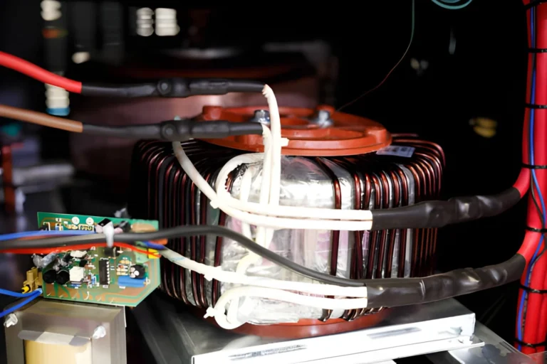
Winding construction styles you’ll encounter (and why they affect performance)
Now let’s shift from “how you wire it” to “how it’s built.” This matters for control transformers because you’re often balancing compact size with decent regulation and manageable temperature rise in a crowded enclosure.
Different sources categorize transformer windings by construction—commonly including rectangular/layer windings and disc windings, with helical variants used for certain current/voltage profiles.
Winding construction style
What it is (plain English)
Typical strengths
Typical trade-offs
Layer (rectangular/cylindrical)
Turns stacked in layers around a former
Common, cost-effective, predictable manufacturing
Leakage and capacitance depend strongly on layout; may be less ideal at very high impulse stresses
Helical (spiral)
Conductor wound in a helix; often for higher current
Handles high current well; good mechanical strength
Can be bulkier; conductor choices affect losses
Disc winding
Winding broken into “discs” (sections) with spacers
Better control of electrical stress distribution; often used in larger units
More complex and typically higher cost
Foil winding
Wide foil strip used as conductor
Low AC resistance at some frequencies; good packing
Not always necessary for typical 50/60 Hz control transformers; may affect heat paths
So what should a buyer do with this? Usually you don’t need to dictate the construction style unless you have unusual constraints: very high inrush demands, elevated ambient temperature, vibration, or strict acoustic limits. But it is useful to ask manufacturers what they use by default for your VA range, because it hints at their cost structure, lead time, and ability to customize.
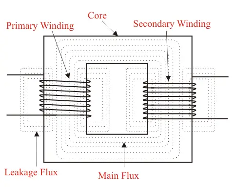
Interleaving, leakage, and the real reason contactors “chatter”
You can size VA “correctly” and still see voltage sag at the secondary during inrush. In many industrial control circuits, the first 30–50 milliseconds of energization can demand several times normal current (that’s the inrush window when coils and solenoids pull hard).
A major contributor to that sag is leakage inductance—energy that doesn’t couple cleanly from primary to secondary because of geometry. Designers mitigate this with winding arrangements such as interleaving (also called sandwiching or sectioning) and sometimes bifilar concepts in other transformer classes.
Multiple technical sources note that interleaving can reduce leakage inductance significantly, and practical design guidance commonly lists interleaving as a method to suppress leakage.
Technique (design-side)
What the supplier changes
Impact you may notice
Cost/lead-time implication
Interleaved (sandwich) winding sections
Primary and secondary sections alternated
Better coupling; less sag under fast load steps; often lower leakage
Slightly higher build complexity; may increase quotation time for custom designs
Constrained by insulation and thermal requirements
Insulation thickness optimization
Adjusts spacing between windings
Better coupling if spacing reduced (within safety limits)
Must stay compliant with IEC/UL creepage/clearance requirements
Separate secondaries for noisy loads
Adds extra isolated winding(s)
Less interaction between coil inrush and sensitive electronics
Adds copper and terminals; increases prices but may cut total system cost
Better documentation of polarity/marks
Clear dot/terminal convention and diagrams
Fewer wiring errors in series/parallel and paralleling scenarios
Minimal cost; large value in reduced field failures
If you’re troubleshooting a control circuit where relays or contactors “chatter,” a productive conversation with the transformer manufacturer is:
What secondary voltage regulation is expected during inrush, not just at steady load?
Is the unit intended for control-circuit duty (with published inrush performance tables), or is it a general-purpose transformer being repurposed?
Some industrial literature explicitly guides buyers to select transformers based on the secondary voltage delivered under inrush conditions (e.g., 85/90/95% columns in selection charts).
How to write an RFQ that suppliers can quote correctly (and competitively)
When B2B buyers say “we need a control transformer,” suppliers hear a dozen open variables. If you want fast, comparable quotes from suppliers and wholesalers (and fewer back-and-forth emails), anchor the request around winding configuration and compliance.
RFQ field
What to specify
Why it affects manufacturability and price
Input voltage(s) and frequency
Exact values (e.g., 400V 50Hz, 480V 60Hz)
Drives multi-tap or dual-primary decisions; impacts temperature rise margin
Output voltage(s)
e.g., 24V, 110V, 120V, dual secondary, center tap
Determines secondary configuration and terminal count
Load profile
Continuous VA + inrush VA estimate
Critical for control duty; reduces under-voltage complaints
Required certifications
UL 5085 series, IEC/EN 61558-2-2, CSA, etc.
Certification scope impacts insulation system, testing, and cost
Environmental conditions
Ambient temp, enclosure type, altitude
Changes thermal design and insulation class choices
Often the difference between “catalog” and “customization”
Custom options
Shielding, extra secondaries, lead wires vs terminals
Adds material and labor; but can cut total panel BOM
Price drivers to expect (so you’re not surprised):
More taps and more terminals usually increase cost modestly, but can reduce total cost of ownership by lowering SKUs.
Extra independent secondaries increase copper and insulation work.
Certification and documentation packages can be a meaningful component of total prices for low-volume builds.
Short lead time and low MOQ often change the pricing curve more than engineers expect.
If you want to encourage a quote that’s both competitive and technically correct, include one sentence like: “Please propose the most economical winding configuration (single, dual, multi-tap) that meets the input range and maintains stable secondary voltage under coil inrush.”
And yes—if you’re ready to move, this is also the right moment to ask for factory-direct support: a manufacturer who can confirm winding configuration, markings, and test data will save you real time during commissioning. If you’d like, share your input/output targets and load type, and you can request a quotation or technical proposal optimized for your panel.
Control Transformer Winding Configurations selection gets much easier once you treat winding configuration as a first-class specification, not an afterthought. For most industrial panels, the “workhorse” choices are multi-tap primaries (for SKU reduction), dual secondaries (for series/parallel flexibility), and—when you want cleaner segregation—multiple independent secondaries. When performance issues show up in the real world (contactor chatter, PLC brownouts), it’s often less about nameplate VA and more about the winding arrangement’s leakage and inrush behavior.
From a B2B perspective, the best results come when engineering and purchasing align early: define the required input range, output(s), inrush expectations, and compliance targets; then let qualified suppliers or manufacturers propose the most economical configuration. Done well, you’ll lower inventory complexity, reduce commissioning failures, and usually achieve better total cost than “cheapest unit that matches the voltage.”
FAQ
Can I parallel two identical secondary windings for more current?
Yes—if the transformer is designed for it and you connect them with correct polarity/phasing to avoid circulating current.
What’s the benefit of a multi-tap primary?
One transformer can serve multiple line voltages, reducing SKUs and simplifying global sourcing.
Is “120/240” the same as “120 x 240”?
Not always. Some catalogs use “/” to indicate a midpoint (center tap) is available, while “x” may indicate series/parallel only.
Why does my 24V control circuit drop to ~20V when a contactor pulls in?
Inrush demand plus leakage/impedance causes sag. Selecting a control-duty transformer based on inrush performance helps.
Does interleaving really help?
Often, yes. Interleaving is widely cited as a method to reduce leakage inductance and improve coupling.
Are buck-boost connections relevant to control transformers?
Sometimes. For small voltage correction, dual-winding units can be wired for buck/boost, but isolation and compliance must be checked.
Have you ever looked inside a control cabinet and wondered why the JBK3 220/24V control transformer for PLC power is there, instead of just running everything straight off the main line? As a transformer sales engineer, I get asked this all the time. The short answer is: safety, isolation, and stable low‑voltage control power. The slightly longer answer […]
Overloading a JBK3 industrial low‑voltage machine control transformer is one of the fastest ways to turn a perfectly good control power supply into a warm‑to‑toasty anxiety trigger. As a transformer seller, I’ve seen more than a few machines shut down because someone simply “plugged in one more relay” without thinking about VA. In this post, […]
If you are an industrial buyer, panel builder, or automation engineer, you have probably seen “control transformer” and “JBK3 control transformer” listed side by side in a catalog. At first glance they look the same. But when you start wiring a machine‑tool panel or an industrial control cabinet, the difference really matters. In this article, […]