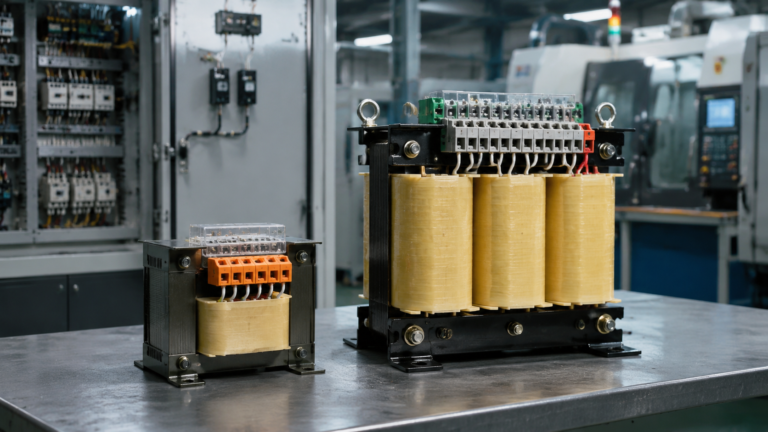
What Is the Working Principle of a Transformer Control?
Published: Author: Lisa
Inside almost every industrial control cabinet there is a small device doing a large job: the control transformer. It takes the higher line voltage — commonly 480 V, 380 V, or 220 V — and steps it down to a low, stable control voltage that is safe for relays, contactor coils, pilot lights, and PLC inputs. If you have ever wondered about the working principle of a transformer control, the answer comes down to two ideas: electromagnetic induction and electrical isolation.
This guide from Hairui Electric walks through how a transformer control works step by step, what sets it apart from an ordinary power transformer, and how to read an auto transformer control circuit diagram. By the end, you will know which control transformer suits your panel and how to size one correctly.
What Is a Transformer Control?
A transformer control — also called a control power transformer (CPT) — is a
step-down transformer built specifically for control circuits rather than for
delivering bulk power. It converts a higher supply voltage into a low control
voltage, most often 120 V, 110 V, or 24 V, and feeds that isolated
supply to contactors, relays, timers, indicator lamps, and PLC power modules.
The key difference from a standard distribution transformer is the way it is rated
and built. A control transformer is optimized for voltage regulation under
intermittent, inrush-heavy loads, so the control voltage stays steady even when a
contactor coil suddenly pulls in. That stability is why a transformer controller
and its associated transformer are treated as a matched pair in well-designed
panels.
The Working Principle: Electromagnetic Induction
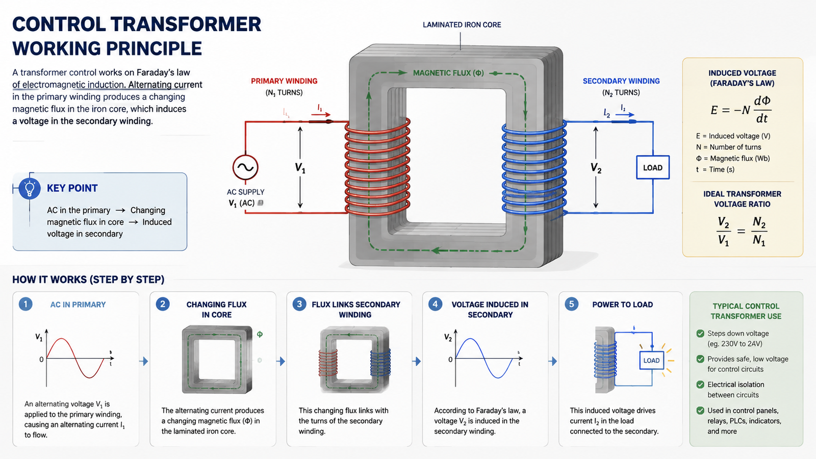
A transformer control works on Faraday’s law of electromagnetic induction.
When alternating current flows through the primary winding, it produces a changing
magnetic flux in the iron core. That flux links the secondary winding and induces
a voltage in it — no direct electrical connection exists between the two sides.
The Turns Ratio Sets the Output Voltage
The voltage on each side is set by the turns ratio: if the primary has more turns
than the secondary, the transformer steps the voltage down in the same proportion.
A 480 V primary with a 120 V secondary has a 4:1 ratio, so the secondary
has one quarter of the primary’s turns. Because power is conserved (ignoring
small losses), a lower secondary voltage means a proportionally higher available
secondary current.
Isolation Protects the Control Circuit
Because the primary and secondary windings are magnetically coupled rather than
electrically connected, the control circuit is isolated from the power line. This
reduces the risk of dangerous fault current reaching the controls, keeps line-side
surges away from sensitive electronics, and lets the control circuit be grounded
independently for safer maintenance.
Regulation, Inrush, and Sealed VA
Contactor coils, solenoids, and relays are the hardest loads a transformer control
must serve. When a coil first energizes, it can draw several times its steady
“sealed” current for a fraction of a second. A control transformer is
designed with a lower internal impedance than a comparable power transformer, so it
can deliver this brief inrush without letting the output voltage sag enough to
drop out other contactors already on the circuit.
Sealed VA — the steady-state load the coil draws once the armature has closed.
Inrush VA — the momentary surge the coil draws when it first pulls in.
Regulation — how much the secondary voltage dips under load, usually kept tight on a CPT.
This is why control transformers are sized in volt-amperes (VA) rather than watts,
and why the inrush VA of the largest coil in the panel is often the deciding
number.
Auto Transformer Control Circuit Diagram
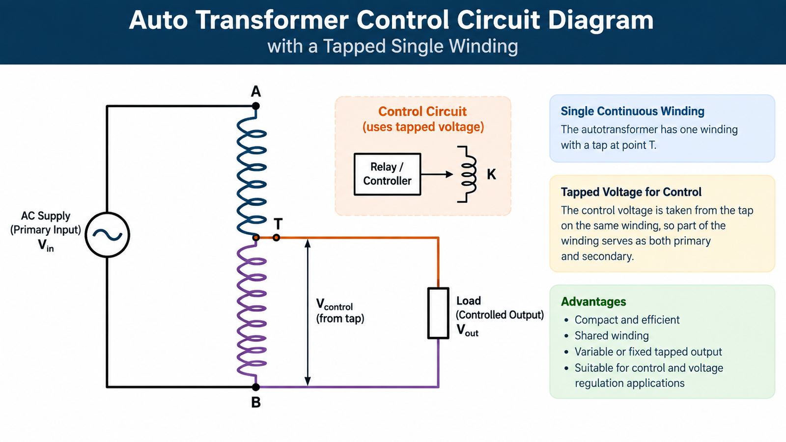
Some control applications use an autotransformer instead of a two-winding
transformer. An autotransformer has a single continuous winding that is tapped,
so part of the winding acts as both primary and secondary. It is smaller and
cheaper for modest voltage changes, but it does not provide galvanic isolation.
In a typical auto transformer control circuit diagram, the incoming line is
connected across the full winding, and the control voltage is taken from a tap
along that same winding. The diagram also usually shows an overcurrent or thermal
protective device and a control fuse on the load side. Autotransformer control is
common where only a small step-down is needed — for example, taking 240 V
down to 208 V — and where a transformer controller manages a variable tap to
hold the output within a set range. For most safety-critical machine-tool and PLC
circuits, however, a fully isolated two-winding control transformer is preferred.
Types of Control Transformers
The right transformer control depends on the machine and the panel. Hairui
Electric’s control transformer range covers the common industrial models:
BK Series Control Transformer — a general-purpose workhorse rated from 50 VA to 2500 VA, with 220 V
or 380 V input and 6 V to 220 V output for machine tools and control
circuits.
R-type transformer — a compact, low-leakage design used where size, low noise, and low magnetic
interference matter.
Model
Best for
Typical input / output
Standout feature
BK Series
General machine-tool control circuits
220 V / 380 V in; 6–220 V out
Broad 50–2500 VA range
JBK3
CNC and automation panels, PLC power
Line voltage to low control voltage
Strong inrush handling
BKJ5
Industrial equipment power conversion
Line voltage to low control voltage
Stable, low-noise output
R-type
Compact, low-interference installations
Line voltage to low control voltage
Low leakage and small footprint
Common Applications
A transformer control shows up wherever a machine needs isolated, low-voltage power
for its controls:
CNC machines and metalworking equipment
PLC panels and industrial automation systems
Motor starters, contactors, and relay logic
Machine-tool work lamps and signaling circuits
Packaging lines and assembly equipment
How to Select and Size a Transformer Control
Sizing is a four-step process, and getting it wrong is the most common cause of a
dead or tripping panel:
Add the sealed VA of every coil and load the transformer will feed.
Add the inrush VA of the single largest coil that will energize at once.
Choose a VA rating that covers inrush plus sealed load with regulation within about 85–90% of rated voltage.
Protect the secondary with a correctly sized fuse or breaker so a shorted coil cannot damage the transformer.
If you are not sure which model fits your application, you can browse the full
selection in the
product catalog, where voltages,
capacities, and mounting options are listed side by side.
Common Mistakes to Avoid
Sizing by watts instead of VA, which under-rates the transformer for reactive coil loads.
Ignoring inrush VA, so the control voltage dips and contactors chatter or drop out.
Using an autotransformer where isolation is required for safety.
Skipping secondary fusing, leaving a shorted coil to overheat the winding.
Forgetting derating for high ambient temperature or continuous duty.
Conclusion
The working principle of a transformer control is simple at its core: electromagnetic
induction steps the line voltage down while isolation keeps the control circuit safe
and stable. The practical skill is matching the transformer to the inrush and sealed
load of the coils it must serve. For more about the manufacturer behind this range,
see our about us page, or
contact us for help choosing and
quoting the right transformer control for your panel.
Frequently Asked Questions
What is the working principle of a transformer control?
It works by electromagnetic induction: an alternating current in the primary
winding creates a changing magnetic flux in the core, which induces a stepped-down
voltage in the isolated secondary winding.
What is the difference between a control transformer and a power transformer?
A control transformer is built for tight voltage regulation under intermittent,
inrush-heavy control loads and is rated in VA, while a power transformer is built
for continuous bulk power delivery at higher efficiency.
What voltage does a control transformer output?
Common secondary voltages are 120 V, 110 V, and 24 V, with many
models offering dual or customizable primaries for 220 V, 380 V, or
480 V inputs.
What is an auto transformer control circuit?
It is a control circuit that uses a single tapped winding as both primary and
secondary to step voltage down without isolation, often paired with a controller
to hold the output within a set range.
How do I size a control transformer?
Add the sealed VA of all loads plus the inrush VA of the largest coil, then select
a rating that keeps regulation within about 85–90% of rated voltage and fuse
the secondary.
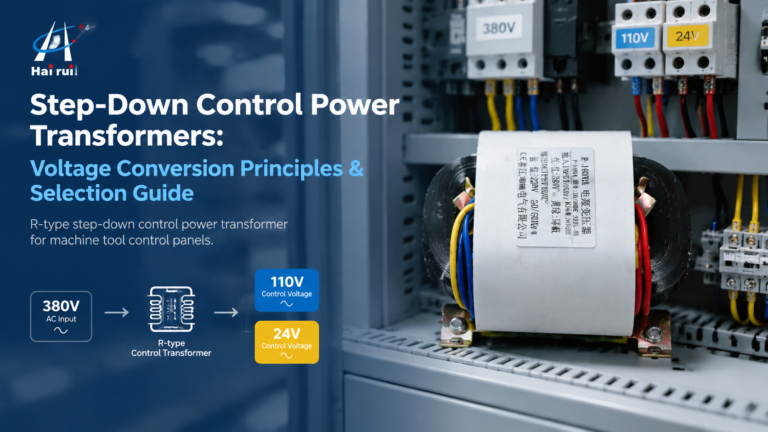
How step-down control power transformers convert 380V/480V line voltage to 110V or 24V control power: turns ratio, VA sizing with inrush, voltage-drop behaviour, wiring and selection.
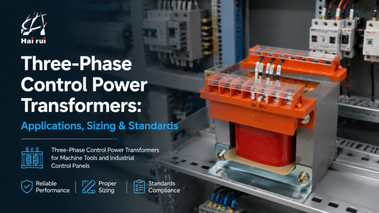
How three-phase control power transformers work, how to size them for machine tool and control-panel loads, and the delta/wye, standards and protection choices that matter in the field.