SF6 Gas-Insulated Switchgear (GIS) vs Ring Main Units (RMU): Key Differences
Published: Author: Lisa
Specifying medium voltage distribution equipment usually comes down to one question: do you need SF6 gas insulated switchgear, or is a ring main unit enough? The two terms are often used interchangeably in tender documents and on datasheets, yet they answer different questions. One is defined by how its live parts are insulated. The other is defined by the network topology it serves. Confusing them leads to over-specified switchrooms, under-protected transformers, and quotations that cannot be compared line by line.
This guide separates the two concepts cleanly. You will get a definition of each, the structural and electrical differences that actually change a specification, a scenario-based selection table, and the standards that govern both. By the end you should be able to read a single-line diagram and say which equipment belongs where — and why.
What Is SF6 Gas-Insulated Switchgear (GIS)?
In the SF6 gas insulated switchgear family, the primary circuit — busbars, switching devices, and connections — is enclosed in a gas-filled tank rather than exposed to air. The gas provides both dielectric insulation and, where a circuit breaker is fitted, arc quenching. Because the live parts sit in a controlled atmosphere, humidity, pollution, salt spray, and small animals stop being design variables.
The defining feature is insulation technology, not the application. A GIS can serve primary distribution, secondary distribution, or both, depending on how it is configured. That is why “GIS” appears in specifications alongside rated currents from 630 A up to 4000 A and short-time withstand currents from 25 kA to 50 kA. The MV GIS family spans a much wider electrical range than a ring main unit ever does.
What is inside a GIS compartment?
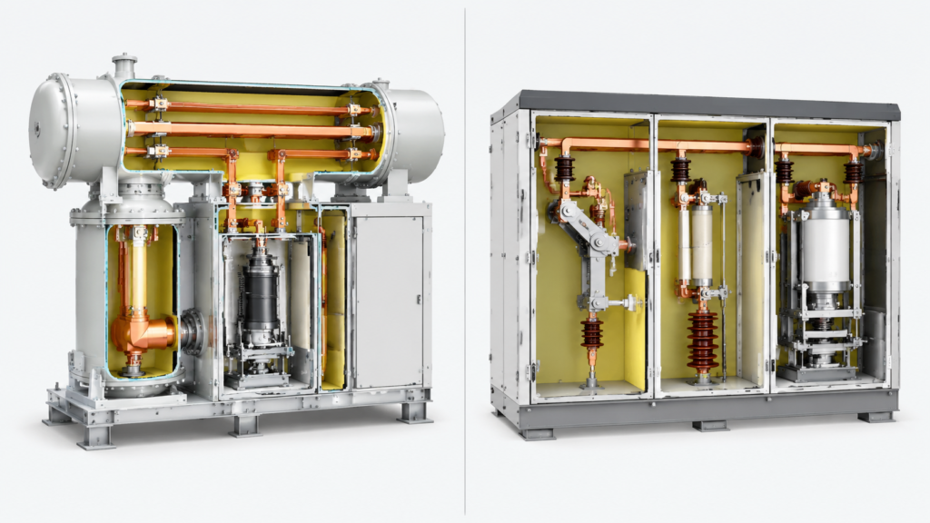
A typical medium voltage GIS assembly separates functions into compartments so that a fault in one does not propagate. You will normally find:
Gas tank — holds the busbar and interrupter or switch assemblies in a sealed, monitored atmosphere.
Switching device — a fixed-type vacuum or SF6 circuit breaker, or a three-position switch combining connect, isolate, and earth functions.
External busbar and cable terminations — often solid-insulated rather than gas-insulated, which keeps the gas boundary small.
Instrument transformers — core-through current transformers on bushings or cables, or epoxy post-type CTs inside the tank with external secondary terminals.
Pressure monitoring — a manometer or pressure switch with alarm and lockout thresholds, so gas loss is detected before dielectric performance degrades.
The practical consequence is a compact, sealed assembly. An example at the 40.5 kV level is this SF6 gas-insulated circuit breaker, where the gas medium handles insulation and arc extinction in the same enclosure — the same engineering logic that lets a GIS occupy a fraction of the floor area of an air-insulated switchboard.
What Is a Ring Main Unit (RMU)?
A ring main unit is switchgear used within a ring network topology, where each distribution loop can be fed from either direction along the ring. If one side of the ring fails, the loop is re-fed from the other side. The result is dual-source reliability from a single upstream feed — which is why RMUs dominate urban load centres, residential compounds, high-rise buildings, and small-to-medium industrial facilities.
An RMU is classified by application, not by insulation. Most conventional RMUs combine load break switches with fuses, sit at or below 630 A rated current, and belong to secondary distribution. Many modern RMUs are, however, built with gas-insulated technology inside — which is exactly where the GIS/RMU confusion originates.
C, F and V modules: the RMU building blocks
Ring main units are assembled from standardised modules, and the module letters appear on virtually every RMU drawing you will receive:
C module — a three-position load break switch / disconnector with an earthing function. Used for incoming and outgoing ring feeders. Rated current is typically 630 A.
F module — a switch-fuse combination. The load break switch handles normal current; the fuse interrupts short-circuit current. This is the economical choice for transformer protection up to roughly 1250 kVA.
V module — a vacuum circuit breaker with a disconnector/earthing switch in series, mechanically interlocked. Used for larger transformers and where relay-based protection and remote control are required.
Because modules share a common tank, interface, and operating convention, an RMU can be delivered as a three-way, four-way, or extended configuration without redesigning the switchroom. A 40.5 kV gas-insulated switchgear cabinet built on C/F/V modules is a good illustration: one cabinet covers load-switch duty, fuse-protected transformer feeders, and vacuum circuit breaker feeders, with a sealed gas chamber and an IP4X housing protecting personnel from the enclosure.
The Overlap: Why “GIS vs RMU” Is Often a False Choice
The most useful thing to understand before comparing the two is that they are not parallel categories. GIS describes an insulation method. RMU describes a network role. A single product can legitimately be both.
Modern RMUs frequently use GIS technology internally — a sealed stainless steel tank containing all live parts and switching functions, with a constant internal atmosphere that delivers high reliability and near-maintenance-free operation. When a supplier advertises an “SF6 RMU,” that is usually what they mean: a ring-network switchgear assembly whose insulation is gas-based rather than air-based or solid-based.
So the real comparison is not “GIS or RMU.” It is a set of narrower questions:
Is the switchgear serving a ring topology, or a radial/primary distribution role?
What rated current and short-circuit duty does the position actually see?
Does the transformer feeder need a fuse, or a relay-protected circuit breaker?
How much floor area and what environmental exposure are you working with?
Does the position need remote monitoring and control?
GIS vs RMU: Side-by-Side Comparison
The table below summarises the differences that show up most often in specifications and quotations. Values are typical ranges — always confirm against the actual type test certificate for the configuration you are buying.
Parameter
SF6 gas-insulated switchgear (GIS)
Ring main unit (RMU)
Classification basis
Insulation technology (gas as insulating medium)
Application (ring / loop network topology)
Distribution role
Primary and/or secondary distribution
Mainly secondary distribution
Typical rated current
630 A up to 4000 A
Up to 630 A (F-module feeders far lower)
Typical short-time withstand
25–50 kA
20 kA/3 s or 25 kA/2 s typical
Main switching device
Fixed vacuum or SF6 circuit breaker; three-position switch
Load break switch, switch-fuse combination, or vacuum circuit breaker
Fault current interruption
Breaker with relay protection; automatic tripping
Fuse (F module) or relay-protected breaker (V module)
Transformer protection limit
Not a defining constraint
Switch-fuse typically up to ~1250 kVA; breaker above that
Footprint
Very compact for its rating; sealed enclosure
Compact; often transformer-integrated or pad-mounted
Environmental immunity
High — sealed tank isolates humidity and pollution
High when gas-insulated; lower for air-insulated variants
Automation readiness
Designed for integrated remote control and monitoring
Available on V-module configurations; basic units are manual
Relative first cost
Higher
Lower for standard ring configurations
Lifecycle cost
Lower maintenance, longer service intervals
Low maintenance when sealed; fuse replacement on operation
Key Differences That Actually Change Your Specification
Rated current and fault duty
This is the difference that eliminates options fastest. A ring main unit is engineered around the 630 A class, which suits distribution feeders and transformer bays in secondary networks. If the position must carry 1250 A, 2000 A, or 4000 A, or must withstand 40 kA for several seconds, you have left the RMU envelope and are specifying primary distribution switchgear.
Note the asymmetry in how fault current is handled. In a fuse-protected RMU, the fuse must be selected to coordinate with upstream and downstream devices, and it must be replaced after operation. In a breaker-based configuration, the protection is reset electronically and can be graded precisely with the rest of the network.
Switching and protection capability
A load break switch is built to make and break normal load current, plus defined duties such as closed-loop transfer, cable charging, and off-load transformer current. It is not a fault-interrupting device. A circuit breaker is. This distinction determines whether you can automate fault clearance at that position or must rely on a fuse or an upstream device.
If your protection philosophy requires fast, selective, resettable fault clearance at the transformer bay, the V-module or breaker-based route is the only correct answer, regardless of how compact the alternative is.
Footprint and installation form
Both technologies are compact, which is why the footprint argument is weaker than it first appears. The real differentiator is the installation form. RMUs are frequently supplied as transformer-integrated or pad-mounted units for outdoor secondary distribution — a box-type substation arrangement where switchgear and transformer share one enclosure. GIS assemblies are more often indoor switchroom equipment, or outdoor enclosures where environmental exposure would otherwise dictate large air clearances.
If your constraint is a switchroom in a dense urban building, the choice is driven by cable entry, busbar extension, and future module addition rather than by tank size. Plan the extension direction before you fix the layout — retrofitting a sealed tank into an unplanned switchroom is expensive.
Automation and remote monitoring
Ring network reliability improves sharply once faulted sections can be isolated and healthy sections restored remotely. Breaker-based and V-module configurations support protective relays, self-powered or auxiliary-powered, and integrate with remote control and monitoring units. Basic load-switch-and-fuse RMUs are manually operated and have no automatic fault interruption capability at the bay.
If your project roadmap includes distribution automation, specify the automation interface now. Adding CTs, VTs, and a monitoring unit to a sealed assembly later is rarely economical.
Cost and lifecycle
Standard ring configurations carry a lower first cost because they use standardised components, simple steel-plate enclosures, and a fuse instead of a breaker and relay. Breaker-based and primary-distribution GIS assemblies cost more upfront because of interrupters, protection, and monitoring.
The trade runs the other way over the asset life. A sealed gas-insulated assembly with a monitored pressure regime and low annual leakage operates close to maintenance-free, and breaker-based positions avoid repeated fuse replacement. For heavily loaded positions with frequent switching duty, the higher first cost is normally recovered. For a lightly loaded ring feeder that switches a few times a year, it usually is not.
How to Choose: Scenario-Based Decision Guide
Match your project to the row that fits, then verify the ratings against the type test data.
Project scenario
Preferred configuration
Reason
Ring network feeders, no transformer protection needed at the bay
RMU with C modules
Load break switch duty only; lowest cost per way
Transformer up to about 1250 kVA on a ring feeder
RMU with F module (switch-fuse)
Economical, well-proven coordination with fuse protection
Transformer above about 1250 kVA, or selective protection required
RMU with V module, or breaker-based GIS
Resettable, gradable relay protection
Urban substation with severe space limits
Gas-insulated assembly, indoor
Sealed tank removes air clearance requirements
Fault level above 25 kA, or rated current above 630 A
Two rules of thumb are worth carrying into a design review. First, choose by fault duty and current, not by product name — the name rarely tells you the rating. Second, decide the protection philosophy before the enclosure type; it constrains the module selection more than any space consideration.
Where the SF6 Circuit Breaker Fits In
Both architectures ultimately depend on the interrupting device inside them. In a GIS or a V-module RMU, that device is a circuit breaker — and its insulation coordination, gas pressure regime, and mechanical endurance set the reliability ceiling of the whole assembly.
On 40.5 kV networks, insulation coordination is usually the deciding parameter rather than breaking capacity alone. A breaker specified with a 95 kV power frequency withstand voltage, for example the LW8-40.5 2000 A breaker with 95 kV power frequency withstand, provides margin against sustained overvoltages on long cable feeders and earth-fault exposure — the same margin that lets a compact gas-insulated assembly sit closer to adjacent equipment without air clearance.
Gas condition monitoring is the other half of the picture. A defined pressure regime — rated pressure, alarm threshold, and minimum functional pressure — converts an invisible failure mode into a measurable one, which matters most in unmanned outdoor installations. Products built around a graded pressure scheme such as SF6 gas pressure monitoring at 0.5 MPa rated, 0.47 MPa alarm, and 0.15 MPa minimum functional pressure are designed for exactly that service pattern.
When you specify the breaker itself, the interrupter type matters too. Puffer, self-blast, dead tank and live tank types differ in energy demand, gas consumption, and how they package into an enclosure — and that choice constrains which switchgear architecture you can build around them. Where the assembly sits outdoors, the same trade-offs described in this guide to indoor vs outdoor SF6 circuit breakers apply one level up. The full range of high voltage SF6 circuit breakers covers 40.5 kV through 252 kV if you are matching a breaker to an existing switchgear envelope.
Standards That Apply
Buyers comparing quotations from different suppliers should insist that the type test certificates cite the same standards. For gas-insulated MV switchgear and ring main units, the relevant set is:
Standard
Scope
IEC 62271-1
Common specifications for high-voltage switchgear and controlgear
IEC 62271-100
High-voltage alternating-current circuit breakers
IEC 62271-102
Disconnectors and earthing switches
IEC 62271-103
Switches for rated voltages above 1 kV up to and including 52 kV
IEC 62271-105
Alternating-current switch-fuse combinations
IEC 62271-200
AC metal-enclosed switchgear and controlgear up to 52 kV
IEC 60529
Degrees of protection provided by enclosures (IP code)
IEC 62271-200 is the one to check first for an RMU or a metal-enclosed GIS assembly, because it governs the enclosure and the internal arc classification. Ask for the internal arc test level and duration — for example AFLR at 20 kA or 25 kA for 0.5 s — since this determines personnel safety provisions and the switchroom layout.
Common Specification Mistakes
Treating GIS and RMU as alternatives. They are different axes. A gas-insulated RMU is both, and comparing a “GIS price” against an “RMU price” without matching ratings produces a meaningless number.
Assuming 630 A is always enough. Confirm the actual load current, including future load growth on the feeder, before fixing the module rating.
Specifying a load break switch for fault interruption. The load break switch handles normal current; fault clearance must come from a fuse or a breaker.
Ignoring fuse coordination. Fuse selection must be graded with upstream and downstream protection, and replacement stock must be planned.
Leaving the gas type and pressure unconfirmed. Where a datasheet lists module data without confirming the insulating gas, the gas specification and pressure must be verified per configuration before selection — nitrogen and SF6 alternatives are not interchangeable in performance or in regulatory treatment.
Designing without the extension direction. Modular assemblies are extendable, but only in the direction and configuration the tank was built for.
Conclusion
SF6 gas insulated switchgear is defined by its insulation technology; a ring main unit is defined by the ring topology it serves. Once you separate those two axes, the specification process becomes straightforward: establish the fault duty and rated current at each position, decide whether the transformer bay needs fuse protection or a relay-protected breaker, then choose the enclosure and installation form that fits the site.
The overlap is real and useful. Most modern RMUs are gas-insulated inside, and both architectures depend on the same circuit breaker technology and the same IEC 62271 series. Compare quotations on ratings, standards, and internal arc classification rather than on product names.
If you are matching switchgear to an existing breaker envelope, or need the breaker ratings confirmed against a single-line diagram before you commit to a module arrangement, send the configuration details and the required fault duty — the electrical ratings and gas specification can be verified before quotation.
Frequently Asked Questions
What is GIS in electrical terms?
GIS stands for gas-insulated switchgear. It is metal-enclosed switchgear in which the primary circuit — busbars, switching devices, and connections — is enclosed in a gas-filled tank instead of being insulated by air. The gas provides dielectric insulation and, where a circuit breaker is fitted, arc quenching. GIS can serve primary distribution, secondary distribution, or both.
Is a ring main unit the same as GIS?
No, but they overlap. A ring main unit is classified by its application in a ring network topology, while GIS is classified by its insulation technology. Many modern RMUs use gas-insulated technology internally, so a single product can correctly be described as both a gas-insulated assembly and a ring main unit.
What is the rated current limit of an RMU?
Conventional ring main units are generally designed around a 630 A rated normal current, with fuse-protected transformer feeders rated far lower. Above that — and above short-time withstand currents of roughly 25 kA — you are normally specifying primary distribution switchgear rather than a standard RMU.
When should an RMU use a circuit breaker instead of a fuse?
Switch-fuse combinations are the economical choice for transformer protection up to roughly 1250 kVA. Above that, or where selective, resettable, and remote-controllable protection is required, a vacuum circuit breaker module with relay protection is the correct configuration. The breaker also avoids repeated fuse replacement after fault operations.
Which standards apply to SF6 gas-insulated switchgear and RMUs?
Both are governed by the IEC 62271 series: IEC 62271-1 for common specifications, IEC 62271-100 for circuit breakers, IEC 62271-102 for disconnectors and earthing switches, IEC 62271-103 for switches, IEC 62271-105 for switch-fuse combinations, and IEC 62271-200 for metal-enclosed switchgear up to 52 kV. IEC 60529 covers enclosure IP ratings.
Is SF6 being phased out of medium voltage switchgear?
Regulatory pressure is increasing because SF6 has a global warming potential in the order of 23,500 times that of CO₂, and some jurisdictions now restrict new SF6 equipment at lower voltage levels. SF6-free alternatives using vacuum interruption with clean air or solid insulation are commercially available. When specifying gas-insulated equipment, confirm the insulating gas and the applicable regional regulation for the project location before finalising the design.
What information is needed for a switchgear quotation?
Provide the single-line diagram, module arrangement, rated voltage and current, fault duty and duration, insulation level, insulating gas specification and pressure, busbar arrangement, cable interfaces, operating mechanism, control voltage, protection and interlocking scheme, indoor or outdoor enclosure, applicable standard, quantity, and destination.
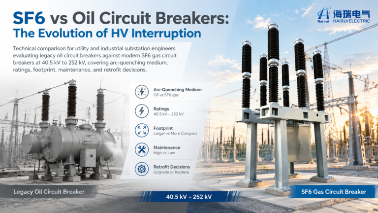
SF6 vs oil circuit breaker comparison: arc-quenching principles, bulk oil vs minimum oil, ratings, maintenance, fire risk, and a practical checklist for replacing legacy oil breakers with SF6 units.
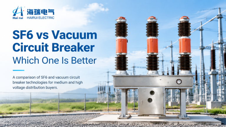
Vacuum or SF6? Compare arc quenching, voltage limits, switching behaviour, maintenance, F-gas rules and cost to pick the right circuit breaker for your network.
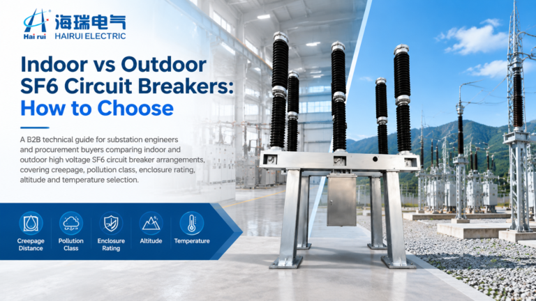
Compare indoor and outdoor SF6 circuit breakers on creepage, pollution class, enclosure rating, temperature limits and altitude, with a six-question selection framework.