Control transformers are the unsung heroes in industrial automation. Whether you’re designing a control panel, automating a process line, or sourcing electrical components for OEM applications, understanding control transformer wiring is essential. These devices play a crucial role in stepping down voltages to safe levels for relays, contactors, PLC systems, and other sensitive control equipment.
In this guide, we’ll walk you through how control transformers work, the principles of proper wiring, key installation tips, and how to avoid common wiring mistakes that could lead to inefficiencies or costly downtime.
What Is a Control Transformer?
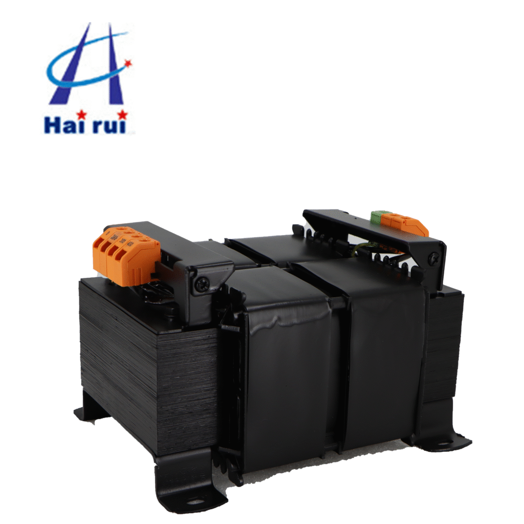
A control transformer, often referred to as an industrial control power transformer (CPT), converts higher line voltage—typically 480V or 240V—into a lower, more stable voltage such as 120V or 24V used for control circuits.
Unlike power transformers that focus on energy transfer efficiency, control transformers are designed to maintain voltage stability during inrush conditions, ensuring reliable operation of control devices.
Specification
Typical Range
Importance
Input Voltage
208V / 240V / 480V
Matches supply line voltage
Output Voltage
120V / 24V / 12V
Powers control circuits
Frequency
50Hz / 60Hz
Matches regional grid
VA Rating
25VA – 5000VA
Determines power capacity
Insulation Class
Class B / F / H
Ensures thermal protection
Understanding these parameters helps engineers select the right transformer for reliable performance in manufacturing plants, HVAC systems, or automation panels.
Improper control transformer wiring connections can result in unstable voltage output, burnt coils, or even safety hazards. A well-wired transformer ensures stable secondary voltage, safe operation, and long service life.
For industrial operations where unplanned downtime equals financial loss, precision in wiring isn’t optional—it’s vital.
Here are three compelling reasons wiring matters:
Voltage Stability: Consistent voltage keeps PLCs, sensors, and relays running smoothly.
Safety Compliance: Proper wiring prevents short circuits and meets UL, CE, or IEC standards.
System Longevity: Reduces electrical stress and overheating, extending equipment lifespan.
Control Transformer Wiring Diagram Explained
Let’s break down the typical control transformer wiring diagram.
A standard single-phase transformer has primary and secondary windings.
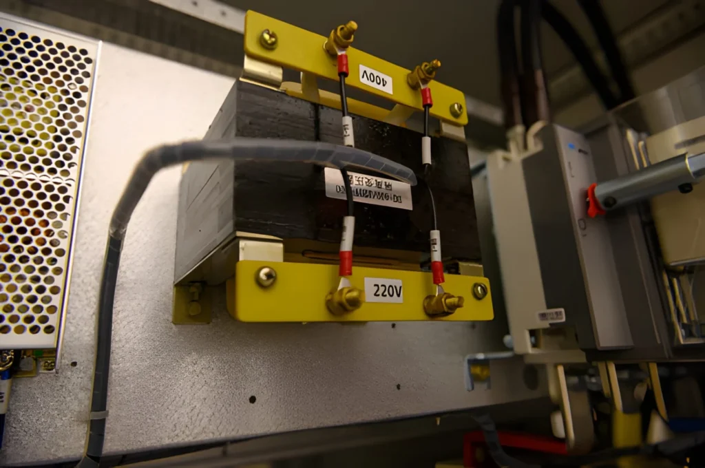
Primary side: Connects to your supply voltage line (e.g., L1 and L2 for 240V AC input).
Secondary side: Delivers the desired control voltage, such as 120V AC, to your control circuit.
Many control transformers also feature tap connections that allow small voltage adjustments to compensate for voltage drops on long cable runs.
Example wiring configuration:
Connection Type
Function
Example Voltage
Primary Terminals (H1, H2)
Input power
240V AC
Secondary Terminals (X1, X2)
Output power
120V AC
Ground
Safety connection
Earth grounding
When wiring, always double-check the nameplate details, follow the wiring schematic provided by the manufacturer, and use appropriate fuses or circuit breakers.
Step-by-Step Control Transformer Wiring Process
Engineers and installers can follow these clear steps to ensure safe wiring:
Disconnect power supply. No live work—safety first.
Identify windings. Use a multimeter to confirm primary (H1-H4) and secondary (X1-X4).
Connect the primary. Match voltage rating to your supply source (e.g., 480V or 240V).
Wire the secondary. Connect load side to your control circuit at the desired voltage.
Ground properly. Avoid noise interference and potential shock hazards.
Perform testing. Measure secondary output voltage before using the system.
Tip: Always label wires for easy troubleshooting during maintenance.
Common Wiring Mistakes and How to Avoid Them
Even experienced technicians make occasional wiring errors. Here are the most frequent ones:
Incorrect tap selection: Using the wrong input tap can cause overvoltage or undervoltage.
Unbalanced load connections: Causes overheating in winding coils.
Lack of fusing protection: Increases the risk of transformer burnout.
Improper grounding: Leads to unstable signals in sensitive circuits.
By avoiding these pitfalls, you extend the life of your transformer and maintain safe, code-compliant installations.
Choosing the Right Control Transformer for Your Application
Selecting the best industrial control transformer involves more than matching voltages. Factors such as load type, inrush current, duty cycle, and environment conditions matter.
Selection Criteria
Description
Example
VA Rating
Amount of power required
500 VA for light systems
Ambient Temperature
Operation environment
40°C standard rating
Mounting Type
Panel mount or DIN-rail
DIN for compact panels
Certification
UL, CE, RoHS
Depends on export market
Enclosure
Open / Encapsulated
Encapsulated for dusty sites
Procurement specialists should also prioritize transformers from reliable suppliers that provide detailed data sheets, warranty support, and quick after-sale service.
If you’re sourcing for OEM or large-scale projects, feel free to send your specifications or RFQ directly—we can help match you with the ideal control transformer assembly.
Safety and Maintenance Tips
Safety is always the top priority. Follow these tips:
Use the correct fuse size on both primary and secondary sides.
Inspect insulation and wire terminations regularly.
Avoid mounting transformers near heat sources.
Confirm that mounting screws are tight to prevent vibration damage.
Record voltage readings periodically for preventive maintenance.
Routine inspection ensures continued performance and minimizes unexpected shutdowns.
Control Transformer Wiring in Automation and HVAC Applications
The applications for control transformer wiring are broad:
Automation Control Panels: Maintain voltage for relays, timers, and solenoids.
CNC and Machine Tools: Stabilize signals for motors and PLCs.
HVAC Systems: Ensure reliable control voltage for fans and compressors.
Lighting and Safety Circuits: Provide secondary voltage for emergency lights and alarms.
Each sector values reliability, and proper wiring ensures consistent operation and compliance with electrical standards.
Understanding control transformer wiring isn’t just about connecting wires—it’s about building reliable, safe, and efficient industrial systems. Whether you’re setting up new equipment, retrofitting existing panels, or sourcing components for large manufacturing facilities, wiring precision can define performance quality.
If you’re planning your next electrical project or procurement batch, contact our technical sales team for expert advice and competitive quotations. We’ll help ensure your transformer wiring setup meets both performance and compliance standards.
FAQ
How do I size a control transformer?
Calculate total VA of all connected loads and add a 25% safety margin.
Can a control transformer run continuously?
Yes, if properly rated and ventilated. Choose encapsulated types for harsh conditions.
What type of wire should I use?
Use copper wire with insulation rated for at least 600V and suitable for the transformer’s operating temperature.
What’s the difference between 24V and 120V control circuits?
24V is safer for human interaction, while 120V circuits provide better performance for heavy-duty control equipment.
How can I reduce transformer noise?
Use vibration-damping mounts, ensure proper grounding, and keep the transformer away from magnetic-sensitive devices.
If you are an industrial buyer, panel builder, or automation engineer, you have probably seen “control transformer” and “JBK3 control transformer” listed side by side in a catalog. At first glance they look the same. But when you start wiring a machine‑tool panel or an industrial control cabinet, the difference really matters. In this article, […]
In most industrial panels, a standard 480V to 120V control transformer is designed to provide a single 120V secondary for control power, not a 120/240V split‑phase system. You can only get 120/240V from it if the secondary is specifically wound and brought out as 120/240V (with a center tap), or if you add an additional […]
Transformers are everywhere in electrical systems. But not all transformers serve the same purpose. If you work with industrial machines, HVAC equipment, CNC systems, or automation control panels, you’ve likely heard the term control transformer. So what makes a control transformer different from a power transformer? In this article, we’ll explore their differences in function, […]
We use cookies to enhance your browsing experience, serve personalised ads or content, and analyse our traffic. By clicking "Accept All", you consent to our use of cookies.