When you think about powering modern industrial systems, control transformers Wiring play a crucial role that often goes unnoticed. These compact devices step down voltage levels to safely supply control circuits, motor starters, and automation equipment throughout facilities worldwide. But getting the wiring right? That can make all the difference between smooth operations and costly downtime.
This comprehensive guide walks you through everything engineers and procurement professionals need to know about wiring a Control Transformer Wiring correctly. Whether you’re installing your first unit or troubleshooting an existing system, you’ll find practical insights backed by industry standards and real-world applications.
Understanding Control Transformers and Their Role
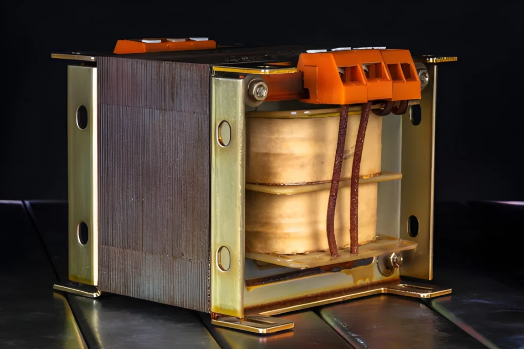
Before diving into wiring procedures, let’s establish what sets control transformers apart from their power counterparts. A control transformer is specifically engineered to supply stable, low-voltage power to control circuits while providing electrical isolation from high-voltage primary systems. Unlike power transformers designed for bulk energy transmission, control transformers excel at handling the unique characteristics of control loads.
These specialized devices typically operate with lower VA ratings—ranging from 50 VA to around 5 kVA—and feature compensated windings that maintain voltage stability even when loads suddenly energize. Their superior voltage regulation becomes critical when contactors, relays, and solenoids draw high inrush currents during startup, often reaching 3 to 10 times their steady-state consumption.
Industrial facilities rely on control transformers across numerous applications. Motor control centers use them to step down 480V or 600V power to 120V or 24V for starter coils and overload relays. Programmable logic controllers require clean, stable voltage that control transformers consistently deliver. Safety systems, emergency circuits, and building automation networks all depend on these transformers to function reliably.
Characteristic
Control Transformer
Power Transformer
Primary Purpose
Supply stable voltage to control circuits
Efficient bulk power transmission
VA Rating
50 VA to 5 kVA
Tens of kVA to hundreds of MVA
Voltage Regulation
Superior (compensated windings)
Standard
Inrush Handling
Excellent
Limited
Typical Applications
Motor starters, PLCs, automation
Power distribution, substations
Understanding these fundamental differences helps you appreciate why proper Control Transformer Wiring practices matter so much for control transformer installations.
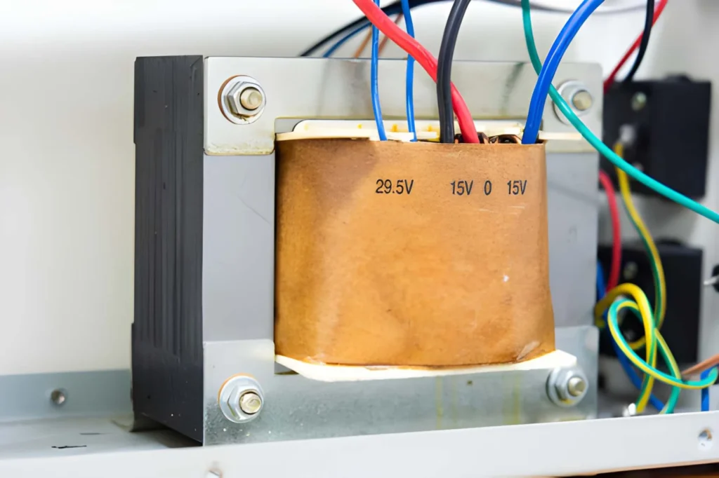
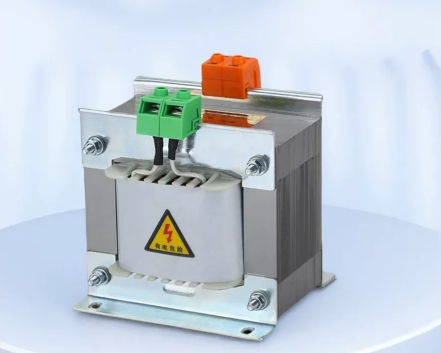
Getting familiar with terminal designations represents your first step toward successful wiring. Control transformers follow standardized marking conventions that tell you exactly where to connect primary and secondary circuits.
The primary winding—which connects to your high-voltage power source—uses terminals marked H1 and H2. Some transformers feature additional primary terminals (H3, H4) when designed for dual-voltage operation. The secondary winding, supplying your control circuit, carries X1 and X2 terminal markings. Industry standards dictate that H1 and X1 always share the same instantaneous polarity, a critical detail when paralleling transformers or maintaining proper phasing.
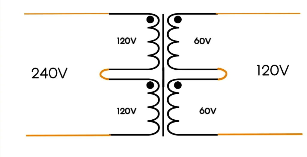
Many industrial control transformers offer dual-voltage capability, providing flexibility for different power systems. A common configuration might feature 240V × 480V primary ratings and 120V × 240V secondary ratings. The multiplication sign indicates dual-voltage operation rather than a voltage range.
Series connections deliver higher voltage. When you need the transformer’s higher voltage rating, connect the windings in series by linking the odd-numbered terminal to the even-numbered terminal of the next winding. For a 480V primary connection on a dual-voltage transformer, you would connect H2 to H3, then apply power to H1 and H4. Each winding carries its rated voltage, and the series connection adds them together.
Parallel connections provide lower voltage. For lower voltage operation, connect the windings in parallel by joining even terminals together and odd terminals together. On a 240V primary, you’d connect H1 to H3 and H2 to H4, then apply power to either pair. This configuration allows higher current capacity at the lower voltage.
The same series-parallel principle applies to secondary windings. Always verify the manufacturer’s wiring diagram before making connections, as improper configuration can damage the transformer or create hazardous conditions.
Step-by-Step Wiring Procedures
Successfully Control Transformer Wiring requires methodical attention to detail and adherence to safety protocols. Let’s walk through the complete process from preparation to final verification.
Pre-installation preparation sets the foundation for safe work. Always de-energize all power sources and apply lockout/tagout procedures before beginning any wiring work. Verify zero energy with appropriate test equipment—transformers can maintain dangerous induced voltages even when apparently disconnected. Gather your tools: screwdrivers for terminal connections, wire strippers, a multimeter for testing, and electrical tape for securing connections.
Examine the transformer nameplate carefully. This data plate specifies primary and secondary voltage ratings, VA capacity, frequency, and connection instructions for dual-voltage configurations. Confirm these specifications match your application requirements before proceeding.
Wiring the primary side brings high voltage to the transformer. Identify your power source voltage—common industrial configurations include 480V three-phase, 240V single-phase, or 208V three-phase systems. Route appropriately sized conductors from your power source to the primary terminals, ensuring cables meet ampacity requirements for the transformer’s full-load current.
For a standard 480V to 120V control transformer, connect the phase conductor to terminal H1 and the neutral or second phase to H2. When working with three-phase systems supplying single-phase transformers, connect across two phases. Dual-voltage primaries require careful attention to the series or parallel connections described earlier.
Tighten all primary terminal screws to the torque specifications provided by the manufacturer. Loose connections create resistance, leading to heat buildup, voltage drop, and potential failure. Many industrial failures trace back to inadequately tightened terminals.
Secondary side connections link the transformer to your control circuit. The secondary typically supplies 120V or 24V to control devices. Connect terminal X1 to your control circuit’s hot conductor and X2 to the common or neutral conductor.
Here comes a crucial safety requirement. National Electrical Code standards mandate secondary grounding when the primary voltage exceeds 150 volts to ground. For most industrial control transformers operating from 240V or 480V primaries, you must bond the X2 terminal to the equipment grounding system. This connection limits dangerous voltage to ground during insulation failures and ensures proper operation of overcurrent protection devices.
Connect a properly sized grounding conductor from the X2 terminal to your control panel’s grounding bus bar, which itself connects to the facility’s grounding electrode system. Never omit this critical safety connection.
Fuse protection installation safeguards both the transformer and your control circuit. NEC Article 450.3(B) provides specific requirements for overcurrent protection on transformers rated 1000 volts or less. Primary-side fuses should be sized at 125% of the transformer’s calculated primary current, though you may round up to the next standard fuse size. For a 500 VA transformer operating at 480V primary, the full-load current calculates to approximately 1.04 amperes, so a 1.25-1.5 ampere fuse would provide appropriate protection.
Secondary overcurrent protection, when installed, should not exceed 125% of the secondary full-load current. Control circuit fuses commonly use Class CC ratings, offering both fast-acting response for control circuits and time-delay options for inductive loads.
The table below summarizes typical transformer configurations:
Primary Voltage
Secondary Voltage
VA Rating
Primary Current
Recommended Primary Fuse
240V
120V
100 VA
0.42 A
0.6 A
480V
120V
250 VA
0.52 A
0.75 A
480V
120V
500 VA
1.04 A
1.5 A
240V
24V
100 VA
0.42 A
0.6 A
Sizing Your Control Transformer Correctly
Proper transformer sizing prevents voltage sags, overheating, and premature failure. The calculation process accounts for both continuous operation and momentary inrush demands that characterize control circuits.
Calculate steady-state VA requirements by listing every control device that operates simultaneously. Include contactor coils, relay coils, indicating lights, timers, and any other continuously energized components. Sum their individual VA ratings to determine your baseline load. For example, a motor starter might have a 20 VA contactor coil plus three 5 VA indicator lights, totaling 35 VA continuous load.
Account for inrush current from inductive devices. When magnetic coils first energize, they draw significantly more current than during steady operation—typically 3 to 10 times their sealed VA rating. A contactor coil rated for 20 VA sealed might pull 100-200 VA during the initial milliseconds of energization. Your transformer must supply this momentary demand without excessive voltage drop.
Calculate the inrush VA by multiplying each inductive device’s VA by its specific inrush factor. Manufacturer datasheets specify these values, but 5x serves as a reasonable default when specific data isn’t available. Add the highest simultaneous inrush VA to your continuous load.
Apply a safety factor of 20-25% to your calculated total. This margin accommodates voltage fluctuations, future load additions, and aging effects. If your calculated requirement totals 150 VA, select a transformer rated for at least 180-190 VA. Standard control transformer sizes include 50, 75, 100, 150, 250, 500, 750, and 1000 VA.
Environmental conditions also influence sizing. Transformers operating in high-temperature locations (above 40°C) may require derating. Consult manufacturer specifications for temperature correction factors.
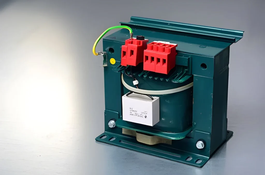
Grounding Requirements and Safety Standards
Proper grounding protects personnel, equipment, and ensures code compliance. Understanding when and how to ground control transformer installations represents a critical aspect of safe electrical work.
Primary-side grounding typically derives from the upstream supply system. The incoming power source should already include proper grounding at the service entrance or distribution panel. However, verify this connection exists—never assume. The transformer’s metal enclosure must be firmly bonded to the equipment grounding conductor regardless of winding connections.
Secondary-side grounding requirements depend on primary voltage levels and installation location. NEC Article 450.10 mandates grounding the secondary under specific conditions. When primary voltage to ground exceeds 150 volts, you must ground one conductor of the secondary. For a typical 480V to 120V control transformer, this requirement clearly applies.
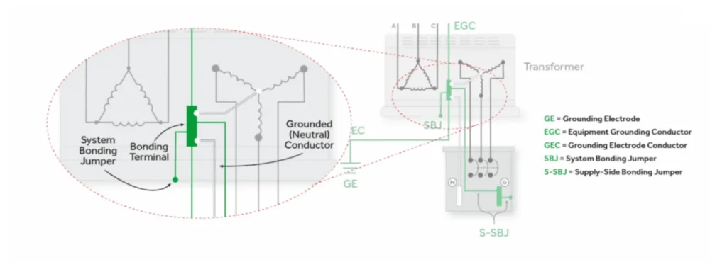
Connect the grounding conductor to the X2 terminal and bond it to the equipment grounding bus. This creates a reference point for the control circuit and provides a low-impedance fault return path. The grounding electrode conductor must be sized according to NEC Table 250.102(C)(1), based on the size of the secondary conductors.
Transformers located in damp or wet locations require secondary grounding regardless of primary voltage. This additional safety measure reflects the increased risk in moisture-present environments.
Bonding the transformer enclosure remains mandatory in all installations. Connect the transformer’s frame or enclosure directly to the equipment grounding system using a properly sized conductor. This prevents the enclosure from becoming energized during insulation failure.
Avoid creating parallel ground paths. The neutral and ground should bond at only one point in separately derived systems. Creating multiple bonds allows fault current to divide between paths, potentially preventing proper overcurrent device operation and creating shock hazards.
Common Wiring Mistakes and How to Avoid Them
Even experienced technicians occasionally make errors that compromise transformer performance or safety. Recognizing these common pitfalls helps you avoid them in your installations.
Ignoring voltage tap settings ranks among the most frequent mistakes. Dual-voltage transformers ship with connections configured for the higher primary voltage. If you’re installing in a 240V system but the transformer came factory-wired for 480V, you must reconfigure the primary jumpers before energizing the unit. Always check and verify tap settings match your actual supply voltage.
Undersizing for inrush current leads to voltage sags that cause contactors to drop out or PLCs to reset. When technicians size transformers based only on steady-state VA without accounting for momentary inrush, the resulting installation exhibits unreliable operation. Use the sizing methodology outlined earlier, including that critical 20-25% safety margin.
Loose terminal connections create high-resistance joints that overheat and eventually fail. Take time to properly tighten every terminal using a torque screwdriver when specifications are available. A quick visual check isn’t sufficient—physically verify each connection is secure.
Omitting secondary grounding violates code and creates serious safety hazards. Some technicians mistakenly believe the isolation provided by the transformer eliminates grounding requirements. As discussed earlier, NEC specifically requires secondary grounding when primary voltage exceeds 150V to ground. Never skip this critical connection.
Inadequate overcurrent protection allows fault currents to damage transformers before fuses or breakers operate. Size primary and secondary fuses according to NEC Article 450.3(B) guidelines. Using oversized fuses “to prevent nuisance tripping” actually increases equipment damage risk and violates electrical code.
Poor wire routing and support stresses bushings and terminals. Cable weight and movement can crack bushings or loosen connections over time. Provide adequate support for incoming and outgoing conductors so no mechanical stress transfers to the transformer terminals.
The following checklist helps catch installation errors before energizing:
Verify supply voltage matches tap setting configuration
Confirm all terminal connections are tight
Check primary and secondary fusing is properly sized
Verify X2 terminal is bonded to equipment ground (when required)
Ensure transformer enclosure is grounded
Inspect wire routing and support
Confirm clearances meet NEC requirements
Review manufacturer’s installation instructions
Need help finding the right Control Transformers?
Feel free to send us your Industrial Control Transformers control voltage specs or inquiry—our technical team will recommend the best fit.
Understanding how to diagnose and resolve control transformer problems saves valuable downtime and helps you maintain reliable operations.
No output voltage often stems from simple causes. First, verify the input voltage at the primary terminals reaches the correct level. Input voltage should fall within ±5% of the nameplate rating. Check that primary fuses haven’t blown and that the upstream disconnecting means remains closed. On dual-voltage transformers, confirm the tap connections match your supply voltage.
If primary voltage is correct but no secondary output appears, test for continuity through both primary and secondary windings using an ohmmeter. An open reading indicates a failed winding. Also check for short circuits between windings or from windings to the core.
Low output voltage under load suggests several possible issues. Measure the no-load secondary voltage first. If it reads correctly without load but drops significantly when control devices energize, the transformer is undersized for your application. Calculate the total VA including inrush current as described earlier, and install a larger unit.
Loose or corroded connections also cause voltage drops. Inspect and tighten all primary and secondary terminals. Use thermal imaging if available to identify high-resistance connections that heat under load.
Overheating indicates the transformer is working beyond its capacity. Check the ambient temperature—transformers have temperature rise ratings based on 40°C maximum ambient. Operating in hotter environments requires derating. Verify the transformer isn’t overloaded by measuring the secondary current and comparing it to the nameplate rating. Ensure adequate ventilation around the unit; blocked cooling paths cause heat buildup.
Humming or vibrating excessively signals mechanical problems. Some humming is normal from magnetostriction in the core, but loud or unusual noises suggest loose core laminations or mounting hardware. Tighten mounting bolts and inspect for loose internal components. Overvoltage on the primary causes excessive magnetization and louder noise.
Frequent fuse failure points to either undersized protection or downstream faults. If primary fuses blow immediately upon energizing, ensure they’re rated at least 1.25 times the full-load input current. Instantaneous failures may indicate a shorted secondary winding or load. If secondary fuses blow during normal operation, check for overload conditions or short circuits in the control wiring.
When troubleshooting, always follow lockout/tagout procedures and use appropriate test equipment. A systematic approach—verifying power supply, checking connections, testing windings, and analyzing load conditions—resolves most issues efficiently.
Maintenance Best Practices for Long Service Life
Regular maintenance keeps control transformers operating reliably and helps identify potential problems before they cause failures. While control transformers require less intensive maintenance than large power transformers, attention to a few key areas pays dividends.
Visual inspections should occur quarterly or whenever you access the control panel. Look for signs of overheating such as discolored windings, burnt terminals, or melted insulation. Check for dust accumulation that impedes cooling, and gently clean the transformer exterior if needed. Inspect connections for looseness or corrosion—retighten any loose terminals you discover.
Temperature monitoring provides valuable condition data. While you don’t need continuous monitoring on smaller control transformers, spot-check the temperature during peak load periods using an infrared thermometer. Surface temperatures significantly above ambient (more than 50-60°C rise) warrant investigation. Modern installations may include temperature sensors connected to building management systems.
Electrical testing confirms transformer health. Annual insulation resistance testing using a megohmmeter reveals degradation before it causes failure. Apply the test voltage specified for the transformer’s voltage class—typically 500-1000V for control transformers—and measure resistance between windings and from each winding to ground. Values below 1 megohm suggest moisture intrusion or insulation breakdown requiring further investigation.
Test the turns ratio annually to verify the transformer still produces correct voltage transformation. This test catches shorted turns within windings. Measure winding resistance to detect loose connections or internal damage.
Connection integrity checks should occur annually or after any mechanical disturbance to the panel. Verify all terminals remain tight, as vibration can loosen connections over time. Inspect wire insulation at termination points for damage or overheating evidence.
Documentation and trending help you spot developing issues. Record test results, temperature measurements, and maintenance actions in a maintenance log. Comparing values over time reveals trends that might indicate approaching failure—for example, gradually increasing temperature or decreasing insulation resistance.
Small control transformers under 500 VA in clean, controlled environments may need less frequent maintenance. Larger units in harsh environments benefit from more aggressive maintenance schedules. Adjust your program based on operating conditions, transformer criticality, and manufacturer recommendations.
If you’re considering an upgrade or new installation, feel free to reach out for expert guidance on selecting the right control transformer for your specific application.
Understanding NEC Code Requirements
Compliance with National Electrical Code standards ensures safe installations and meets inspection requirements. Several NEC articles directly govern control transformer installations.
Article 450.3 specifies overcurrent protection requirements for transformers rated 1000 volts or less. Table 450.3(B) provides the fundamental rules. When protecting only from the primary side, fuses or circuit breakers must not exceed 125% of the primary full-load current. You may round up to the next standard overcurrent device rating per NEC 240.6(A).
Alternatively, you can use dual protection with primary fuses at up to 250% of primary current (no rounding up) and secondary fuses at 125% of secondary current (rounding up permitted). This dual approach often better protects both the transformer and secondary conductors.
Article 450.13 addresses accessibility. Transformers must be readily accessible to qualified personnel for inspection and maintenance. The code permits exceptions for dry-type transformers rated 600 volts or less when located in the open on walls, columns, or structures, or when installed in hollow spaces of buildings not permanently closed in by structure.
Grounding requirements appear in Article 450.10. As discussed earlier, transformers must comply with Article 250 grounding provisions. When control transformers create separately derived systems, one conductor of the secondary must be grounded when required by Section 250.20.
Clearance requirements in Article 450.21 specify minimum working space around transformers. Dry-type transformers rated 112.5 kVA or less must maintain at least 300mm from combustible materials unless separated by fire-resistant barriers. Larger transformers may require installation in fire-resistant rooms. Adequate working space for maintenance and inspection must be provided per Article 110.26.
Conductor sizing follows Article 310. Primary and secondary conductors must have ampacity sufficient for the load and transformer ratings. When relying solely on primary overcurrent protection, primary conductors must have ampacity at least equal to 125% of the transformer’s rated primary current.
Understanding these code provisions ensures your installations pass inspection and operate safely. When questions arise about specific applications, consult with electrical inspectors or code experts before proceeding.
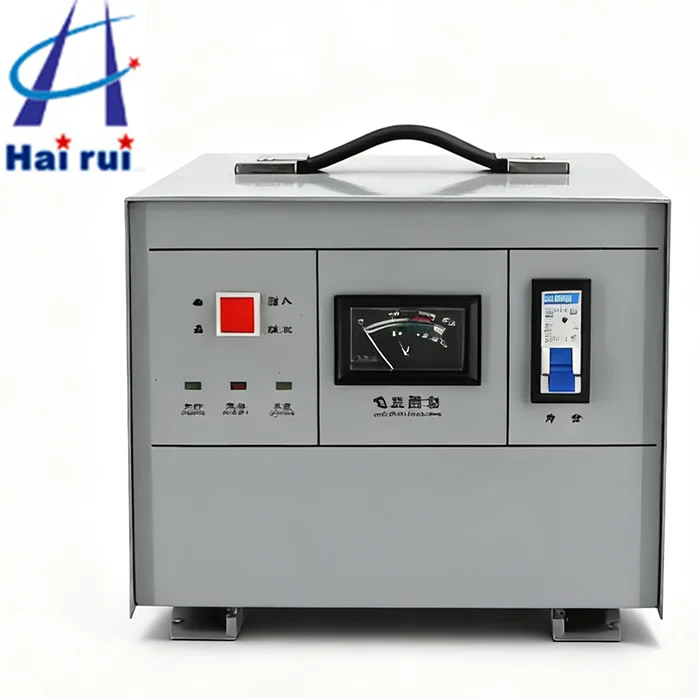
Industrial Applications and Real-World Examples
Seeing how control transformers function in actual industrial settings brings these concepts to life. Let’s examine several common applications.
Motor control centers represent the most widespread control transformer application. A typical MCC supplies 480V three-phase power to motors while using 120V for control circuits. Each motor starter bucket contains a control transformer stepping 480V down to 120V for the contactor coil, overload relay, start/stop pushbuttons, and indicating lights.
For a 50 HP motor starter with a contactor drawing 15 VA sealed and 100 VA inrush, three indicator lights at 5 VA each, and an overload relay at 10 VA, the total steady-state load equals 40 VA. With inrush, you need a transformer rated for at least 125 VA (100 VA inrush + 40 VA steady-state) × 1.25 safety factor = 175 VA. Specifying a 250 VA control transformer provides ample capacity.
PLC systems require clean, stable power that control transformers reliably deliver. A programmable logic controller might operate on 24VDC power derived from a 120V AC supply. The control transformer steps 480V to 120V, feeding a DC power supply that creates the 24VDC. This two-stage approach isolates the sensitive PLC from power line disturbances while maintaining proper voltage during momentary sags.
An automated production line might use multiple PLCs, each drawing 50 watts, plus I/O modules, sensors, and communication equipment totaling 300 watts of 120V load. A 500 VA control transformer (remembering VA ≈ watts for resistive/electronic loads) provides adequate capacity with margin for expansion.
Building automation systems use control transformers throughout. HVAC controls, lighting controllers, access control systems, and fire alarm panels all require low-voltage power. A typical commercial building might have dozens of control transformers stepping 277V or 480V down to 24V for these systems.
For a rooftop HVAC unit, a control transformer supplies 24V to the thermostat circuit, damper actuators, and economizer controls. The transformer must handle the simultaneous inrush when multiple actuators receive position commands. Proper sizing prevents voltage sags that could cause the system controller to reset.
Safety and emergency systems demand reliable control power. An emergency generator transfer switch uses a control transformer to supply power for the transfer mechanism, status indicators, and control logic. These transformers must maintain voltage during the high inrush current of transfer mechanism solenoids.
In chemical processing plants, safety interlocks and emergency shutdown circuits rely on control transformers for dependable power. The consequence of failure in these applications justifies redundant transformers and regular maintenance verification.
These examples demonstrate why understanding proper wiring, sizing, and maintenance matters. Each application presents unique challenges that proper transformer selection and installation address.
Mastering control transformer wiring combines technical knowledge with careful attention to detail. The fundamentals we’ve covered—understanding terminal markings, following proper wiring sequences, sizing for both steady-state and inrush loads, implementing code-compliant grounding, and maintaining installations over time—form the foundation for reliable control systems.
Remember these key takeaways as you plan your next installation. Always verify supply voltage matches tap configurations before energizing. Size transformers to handle both continuous loads and momentary inrush current with adequate safety margin. Ground the secondary when primary voltage exceeds 150V to ground. Protect both primary and secondary circuits with appropriately sized overcurrent devices. Maintain secure terminal connections and adequate clearances around the transformer.
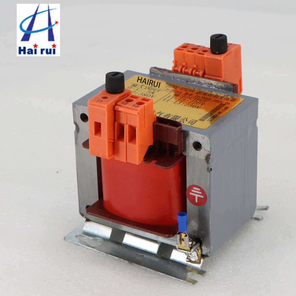
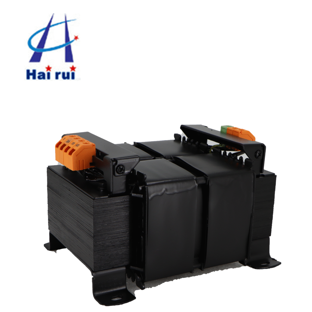
Quality matters when selecting JBK3 Machine Tool Control Transformer for critical applications. Units meeting UL and CSA standards provide assurance of proper design and construction. Consider the operating environment—moisture, temperature extremes, and vibration all impact transformer selection and installation requirements.
Regular maintenance prevents unexpected failures. Implement periodic visual inspections, temperature monitoring, and electrical testing appropriate to your transformer size and application criticality. Document results to identify trends that might indicate developing problems.
When questions arise during your installations, don’t hesitate to consult manufacturer technical support, reference the National Electrical Code, or seek advice from experienced electrical engineers. The modest time invested in getting details right pays dividends through years of trouble-free operation.
Whether you’re powering a single motor starter or complex automation system, proper control transformer wiring provides the stable, safe power your control circuits need. Apply these principles consistently, and your installations will deliver the reliability modern industrial operations demand.
Looking for high-quality control transformers for your next project? Contact us today to discuss your specific requirements and let our engineering team help you select the ideal solution.
Need help finding the right Control Transformers?
Feel free to send us your Industrial Control Transformers control voltage specs or inquiry—our technical team will recommend the best fit.
What wire size do I need for control transformer connections?
Wire size depends on the transformer’s current rating and the circuit protection used. Calculate the primary full-load current by dividing VA rating by primary voltage (for single-phase). For example, a 500 VA transformer at 480V draws 1.04 amperes primary current. Wire ampacity should exceed 125% of this value, so 14 AWG copper wire (rated 15A in typical conditions) provides adequate capacity. Secondary conductors require similar calculations based on secondary current. Always verify local code requirements.
Can I wire a control transformer for 240V when the nameplate shows 480V?
Yes, if the transformer features dual-voltage primary windings. Check the wiring diagram on the nameplate or in the instruction manual. You’ll need to reconfigure the primary winding jumpers from series connection (for 480V) to parallel connection (for 240V). Never simply apply 240V to a transformer wired for 480V without reconfiguring—you’ll severely overexcite the core, causing excessive current draw and overheating.
How do I know if my control transformer needs secondary grounding?
NEC Article 450.10 requires secondary grounding when the primary voltage to ground exceeds 150 volts or when the transformer is located in a damp/wet location. Most industrial control transformers operating from 240V or 480V primaries require secondary grounding. Connect the X2 terminal to the equipment grounding bus bar. When in doubt, consult with a licensed electrician or electrical inspector.
What causes a control transformer to overheat?
Common causes include overloading (exceeding the VA rating), inadequate ventilation, high ambient temperature, loose connections creating resistance, and shorted turns within the windings. Verify the connected load doesn’t exceed the transformer rating, ensure air can circulate around the unit, check that ambient temperature remains below 40°C, tighten all terminals, and test winding resistance to detect internal faults.
Can I use a control transformer for lighting circuits?
Control transformers can supply lighting circuits provided the load characteristics match the transformer’s capabilities. Incandescent lighting presents largely resistive load suitable for control transformers. LED lighting with electronic drivers may introduce harmonics that affect transformer performance—verify compatibility. For large lighting loads, consider transformers specifically designed for lighting applications with appropriate inrush handling.
Why does my control transformer hum loudly?
Some humming is normal from magnetostriction in the laminated core. Excessive noise suggests loose core laminations, mounting bolts, or overvoltage conditions. Verify the primary voltage doesn’t exceed nameplate ratings by more than 5%. Tighten the transformer mounting and check that nothing vibrates in resonance with the 60Hz fundamental frequency. Very loud humming or buzzing may indicate core saturation from incorrect tap settings.
In every industrial facility, behind the hum of machines and the glow of control panels lies a quiet hero — the standard control transformer. It doesn’t grab headlines or require much attention, but without it, the electrical systems that monitor, automate, and protect your operation simply wouldn’t function reliably. In this article, we’ll take a closer […]
When you wire a 480V to 120V control transformer Wiring correctly, you get stable low‑voltage power for control circuits, PLC I/O, contactor coils, and panel auxiliaries—wired incorrectly, you get nuisance trips, overheated transformers, or even damaged equipment. This guide walks engineers, panel builders, and purchasing teams through how the wiring diagram works, typical 480V primary […]
When you’re sourcing electrical components for your system, it’s common to wonder — “Can I use a general transformer instead of a control transformers?” At first glance, they seem quite similar. Both devices step voltage up or down, both rely on electromagnetic induction, and both come in similar enclosures. However, when it comes to reliability, efficiency, and […]
We use cookies to enhance your browsing experience, serve personalised ads or content, and analyse our traffic. By clicking "Accept All", you consent to our use of cookies.