When electrical engineers open a control panel drawing, they don’t rely on photos or 3D models. They rely on symbols. If your control transformer is not shown with the right electrical symbol, you risk misunderstandings, wrong wiring, and even failed inspections.
This blog walks you through the control transformer symbol, how it appears in electrical schematic diagrams, and what B2B buyers (panel builders, OEMs, machine manufacturers, integrators) should look for when selecting and documenting control transformers.
Along the way, you will also see how control transformer wiring diagrams, standards, and symbol conventions help your team communicate clearly and avoid costly mistakes.
What is a control transformer?
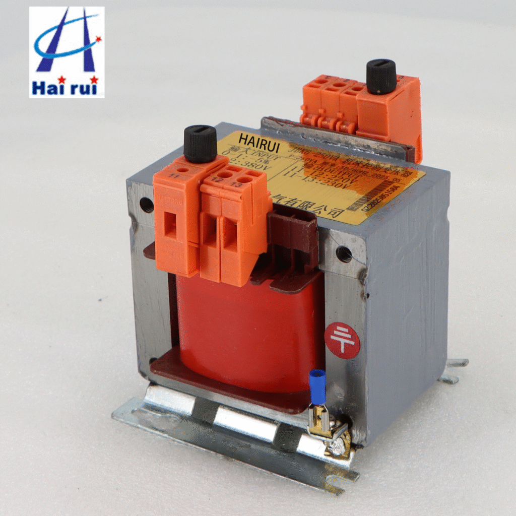
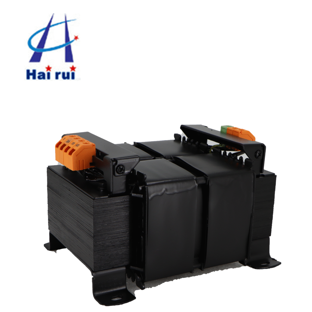
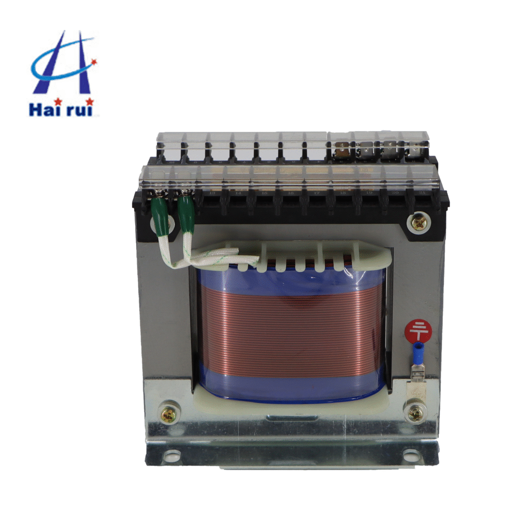
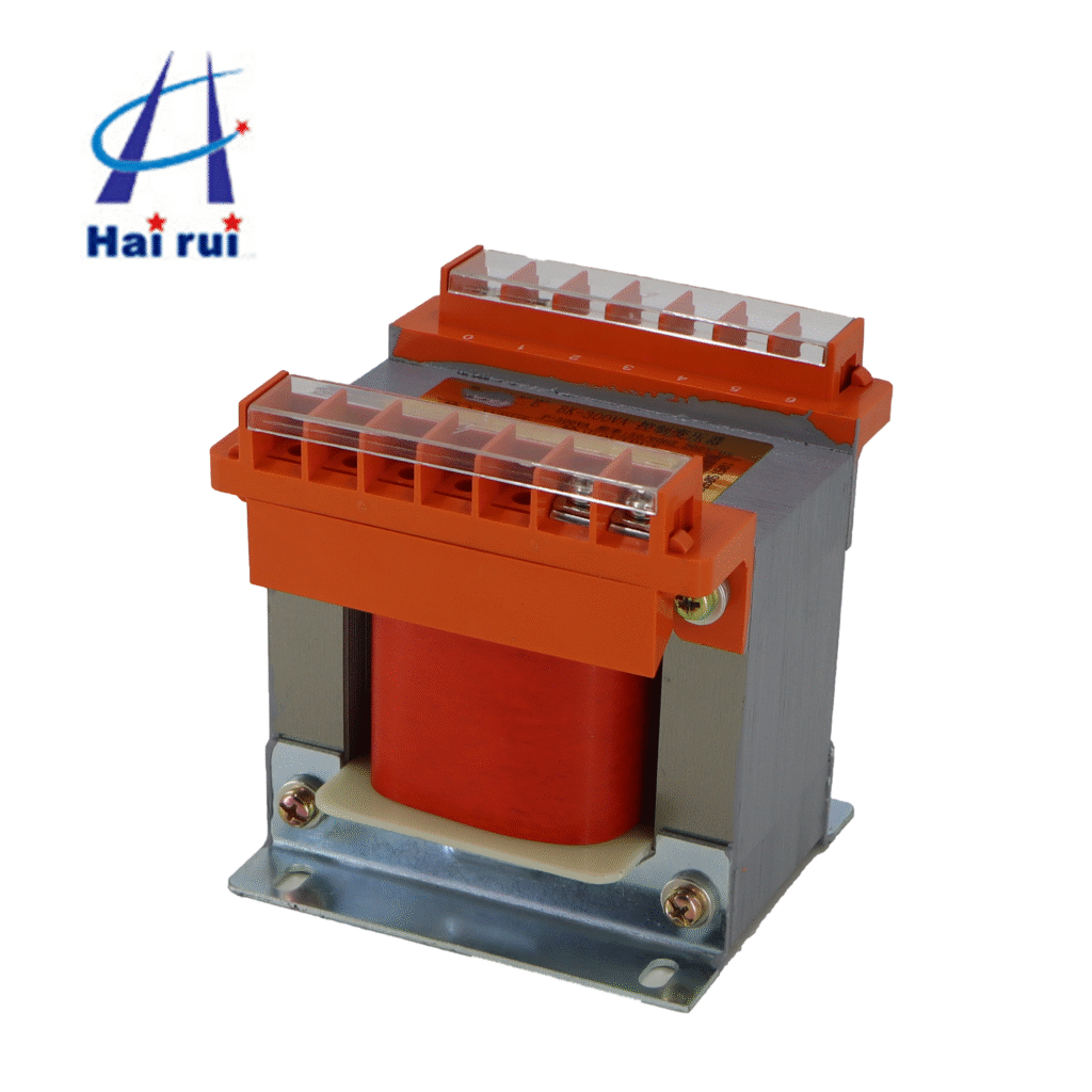
A BK Series Control Transformercontrol transformer is a special type of low voltage transformer used to supply stable power to control circuits. Instead of feeding motors or heavy loads, it feeds devices like:
In industrial control panels, a control transformer typically:
Steps down from 480 V / 400 V / 380 V / 230 V to 120 V / 110 V / 24 V for control
Provides electrical isolation between power and control circuits
Improves safety and reduces electrical noise in sensitive control wiring
So why is the control transformer symbol so important? Because every designer, electrician, and maintenance engineer must instantly recognize:
Where the control circuit starts
Which voltage is used
How the transformer is connected
If your team works across plants, countries, or with external partners, using consistent symbols for control transformers is not just “nice to have” – it is a basic requirement.
Common control transformer symbols
The electrical symbol for a control transformer is usually based on the general transformer symbol: two coils (windings), often parallel or facing each other, sometimes with a core line between them.
The exact look depends on the standard (IEC, ANSI/IEEE, JIS, etc.), the CAD library, and the level of detail.
Here is a simple overview you can share with your design team:
Symbol type
Typical look (schematic description)
Use case
Generic transformer
Two parallel coils with lines or curves, sometimes with a core line between
Any transformer, not necessarily control
Control transformer (IEC)
Two coils, primary and secondary, sometimes labeled with different voltages and tags
Control circuits in IEC-style diagrams
Control transformer with center tap
Secondary coil with a tap in the middle, marked as 0 V or neutral
120/240 V or 24/0/24 V control supplies
Isolation transformer symbol
Similar to generic transformer but sometimes with additional separation indication
For galvanic isolation
Autotransformer symbol
Single winding with tapping points
Rare in low-voltage control, but important to distinguish
Single‑phase transformer symbol
Two windings, sometimes with 1~ label
Most control transformers in control panels
In most control panel schematics, the control transformer symbol is drawn together with:
Primary voltage label (for example: 400 V, 3‑phase L1–L2 or L1–N)
Secondary voltage label (for example: 24 V AC)
Terminal numbers (for example: X1, X2 for primary; X3, X4 for secondary)
Protective devices (fuses or circuit breakers on the primary; fuse or MCB on the secondary)
This combination gives installers everything they need: symbol, rating, and connection points.
How control transformer symbols appear in schematic diagrams
In a control schematic diagram, the symbol for the control transformer is not isolated. It sits in a logical position between incoming power and the control circuit.
Below is a typical layout overview:
Location in diagram
What you see
Why it matters
Power section (left/top)
Incoming mains, main breaker, fuses, then primary side of control transformer
Shows where control power is derived from
Control power section
Secondary side of control transformer with secondary fuses and terminals
Indicates control voltage and protective devices
Control circuit pages
24 V or 110 V control rails feeding relays, contactors, PLC, etc.
Links control devices back to one clear power source
Terminal block page
Control transformer secondary to terminal strip and field wiring
Helps wiring technicians in the panel shop and on site
To make life easier for your team, many designers:
Add the transformer tag (for example: T1, TR1, or K01) next to the symbol
Place voltage labels clearly: “Prim: 400 V, Sec: 24 V AC”
Add a short note such as “Control transformer for PLC and relays”
This sounds simple, but it reduces questions during production and commissioning.
Example of typical labels in a control transformer symbol
Label
Example value
Meaning
Device tag
T1 / TR1
Device ID in BOM and panel layout
Primary
400 V AC, L1–L2
Supply voltage and connection
Secondary
24 V AC
Control voltage level for relays, PLC, etc.
Power
160 VA / 250 VA
Transformer VA rating
Standard
IEC 61558, UL 5085
Compliance and safety reference
When your electrical schematic diagram uses clear control transformer symbols plus these labels, it becomes much easier for B2B customers, inspectors, and partners to validate your design.
Affordable price, huge discount!
Upgrade your power system today with reliable controltransformer! Contact us now for control transformer symbol custom solutions and expert support.
Key standards and naming for control transformer symbols
One challenge in global projects is that different teams may use different symbol styles. A European OEM may work under IEC conventions, while a North American plant expects ANSI/IEEE style symbols.
Here is a high-level comparison:
Region / standard
Symbol style for transformer
Typical tag names
IEC (EN)
Simple, minimalist transformer symbol with two coils
T1, TR1, T‑01
ANSI / IEEE
Similar coils, sometimes drawn slightly differently, with more annotation
XFMR‑1, T1, CPT (for control power transformer)
UL/CSA drawings
Often follow ANSI symbol style plus UL/CSA references
CPT‑1, XF‑1
JIS (Japan)
Transformer symbol similar but documentation in JIS
T1, TP1
If your company exports control panels, consider:
Defining a standard symbol set in your CAD system
Preparing template pages: one for IEC, one for ANSI, etc.
Clearly noting “control transformer” in the legend or symbol list
Customers often ask for “control transformer symbol according to IEC 60617” or “UL‑compliant control transformer schematic”. Even if the graphical appearance is nearly the same, showing the right reference standard in your documentation builds confidence.
Reading control transformer wiring diagrams
A control transformer wiring diagram goes one step deeper than a simple schematic symbol. It shows how to connect actual terminals on the device.
For example, a typical single‑phase control transformer might have:
Primary terminals: H1, H2 (and sometimes H3, H4 for dual primary 230/460 V)
Secondary terminals: X1, X2 (and sometimes X3 for center tap)
Here is a typical mapping table that appears in wiring diagrams or datasheets:
Terminal mark
Function
Example usage in diagram
H1 – H2
Primary winding
Connected to supply (e.g., L1–L2 or L–N)
H1 – H3 / H2 – H4
Dual primary, series or parallel
Series for 400/480 V, parallel for 200/240 V
X1 – X2
Secondary winding
Connected to 24 V AC control circuit
X2 – X3
Center tap / neutral
Used for split secondary (e.g., 24/0/24 V)
On the electrical drawing, you will see the same terminal marks near the control transformer electrical symbol, often with a note like:
Connect H1–H4 for 480 V; connect H1–H2 for 240 V (refer to transformer nameplate).
For installation teams and field technicians, a clean wiring diagram with a correct symbol is more useful than many pages of text.
If you are a B2B buyer specifying control transformers for panel building, ask your supplier for:
PDF wiring diagrams with clear symbols
DWG/DXF blocks for your CAD system
Native library files (for example, EPLAN macro, AutoCAD block, etc.)
This saves engineering time and reduces errors during drawing creation.
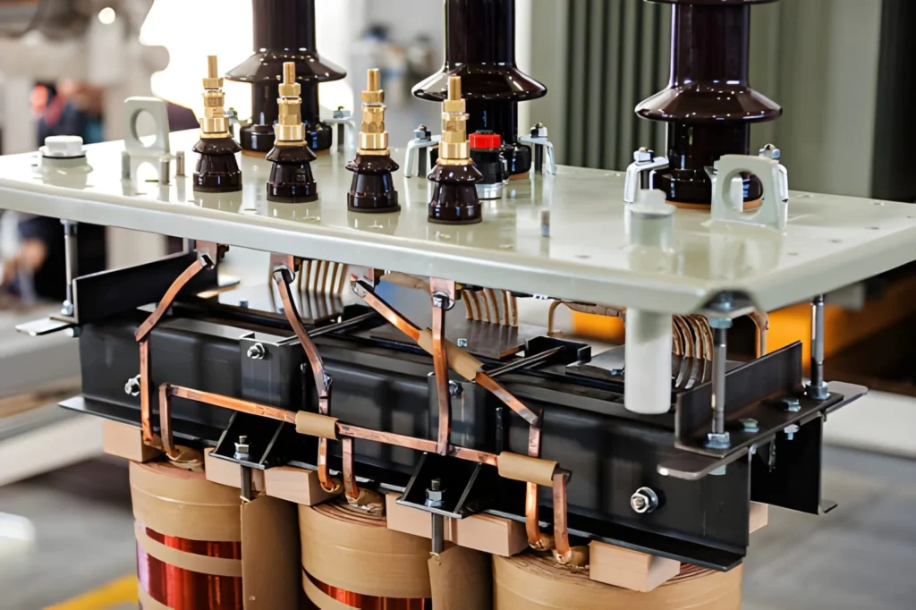
Control transformer vs. power transformer: symbol differences
Control transformers and power transformers share the same basic physical principle, but their symbols and context in diagrams tell a different story.
Consider the practical differences:
Feature
Control transformer
Power transformer
Main function
Supply low‑power control circuits
Distribute large amounts of power
Typical power rating
25 VA – 1000 VA (commonly 63–500 VA)
kVA to MVA range
Voltage levels
400 → 24 V, 230 → 110 V, etc.
10 kV → 0.4 kV, 0.4 kV → 0.23 kV, etc.
Location in diagram
Inside control panel, near PLC and relays
In substation or main distribution area
Symbol annotation
Small device tag (T1, TR1), control voltage notes
Major device tag (TR‑1), detailed power ratings
On the drawing:
Power transformer symbols are usually placed in high‑voltage or main distribution parts of the diagram, with detailed tap information, cooling symbols, etc.
Control transformer symbols are compact, often annotated simply with primary/secondary voltages and VA rating, and grouped with contactors, MCBs, and PLC components.
If you mix symbols or forget to specify that a transformer is a control transformer, technicians may misinterpret its function, causing wrong wire sizing, protective device selection, or even overload conditions.
Practical design tips for using control transformer symbols
To make your schematics clearer and more professional, consider these easy but effective practices:
Design tip
Benefit for your project
Use a dedicated symbol for “control transformer” in your CAD library
Visual clarity; avoids confusion with power transformers
Always show primary and secondary voltages next to the symbol
Faster understanding, fewer questions
Add VA rating and frequency (50/60 Hz)
Helps in load checks and approvals
Show primary and secondary fuses or breakers
Demonstrates compliance with safety standards
Use consistent device tags (T1, T2, etc.)
Easier BOM generation and maintenance
Provide a legend / symbol list page
Helpful for external reviewers and inspectors
From a purchasing perspective, clear drawings also make it easier to standardize and reorder control transformers across multiple projects and panels.
If your company needs a stable, long‑term partner for control transformer supply, including engineering support and symbol libraries, feel free to send your drawing or BOM for a quick quotation and technical check.
A control transformer is a small component in physical size, but it plays a critical role in your electrical control system. The electrical symbol that represents it in your schematic is even smaller, yet it carries a lot of meaning:
Where control power comes from
Which voltage is used
How circuits are isolated and protected
By using standard, well‑drawn control transformer electrical symbols, clear voltage labels, and consistent wiring diagrams, you help every party in the project chain: design engineers, panel builders, commissioning teams, and maintenance staff.
If your company is planning new control panels or upgrading existing equipment and you need reliable control transformers plus ready‑to‑use CAD symbols and wiring diagrams, feel free to reach out with your technical requirements or sample drawings for a detailed quotation and engineering support.
FAQ
What is a control transformer?
It’s a transformer that supplies stable low voltage for control circuits, isolating sensitive components from main power.
How do I select the right control transformer?
Calculate the total VA required by your control components and add extra capacity for inrush current.
Does the symbol for a control transformer differ from a standard transformer?
Yes, it usually includes a label like “CT” or “control” in the schematic for easy identification.
Is output voltage regulated by a control transformer?
No, output voltage depends on the input voltage and transformer turns ratio.
Can a control transformer be used in reverse?
It’s possible, but the output may be lower than specified due to the winding design.
Table of Contents
Affordable price, huge discount!
Upgrade your power system today with reliable controltransformer! Contact us now for control transformer symbol custom solutions and expert support.
In the world of industrial automation and power distribution, control transformers play a small yet pivotal role in ensuring stable voltage and reliable performance. Whether you’re an electrical engineer designing complex control panels or a procurement specialist sourcing reliable components from trusted control transformer suppliers, understanding the core and winding designs of control transformers can help you make […]
People often ask: what exactly is a Control Transformer, and why does it matter in industrial applications? If your operation includes control panels, relays, sensors, or machine automation, a dedicated control transformer can be the unsung hero of reliability and safety. In this article, we’ll demystify the concept, walk through how it works, outline essential […]
If you buy or spec control transformers often, you’ve probably noticed a pattern: many “selection mistakes” are not really about VA rating or even voltage—they’re about how the windings are arranged and brought out to terminals. Those choices determine whether your panel gets stable control power during contactor inrush, whether you can reuse one part […]
We use cookies to enhance your browsing experience, serve personalised ads or content, and analyse our traffic. By clicking "Accept All", you consent to our use of cookies.