
Description
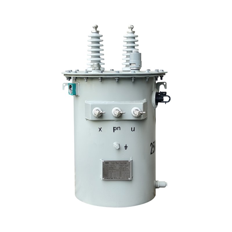
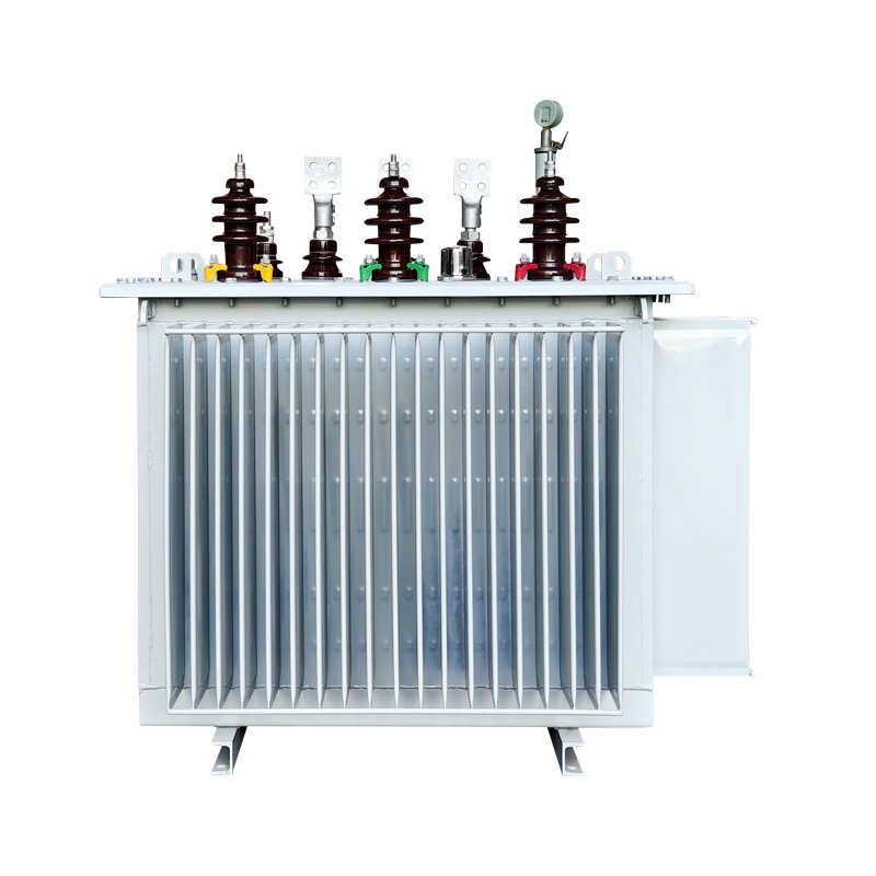
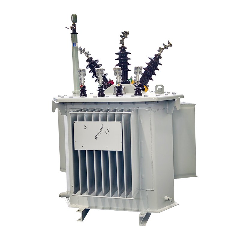
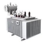
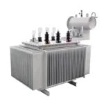
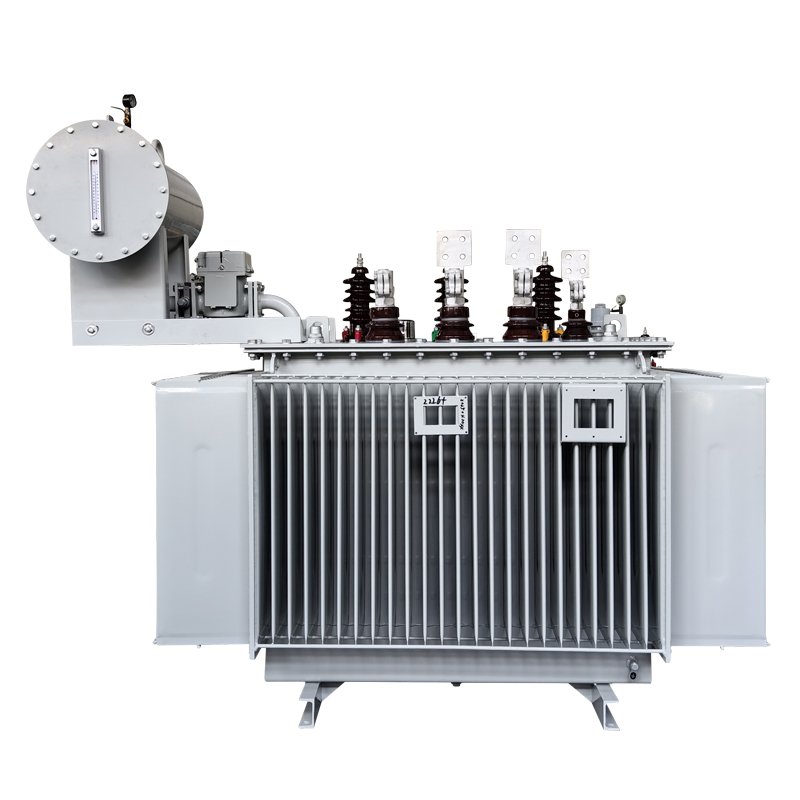
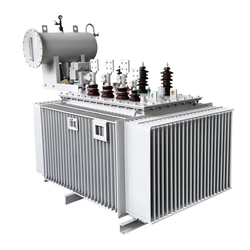
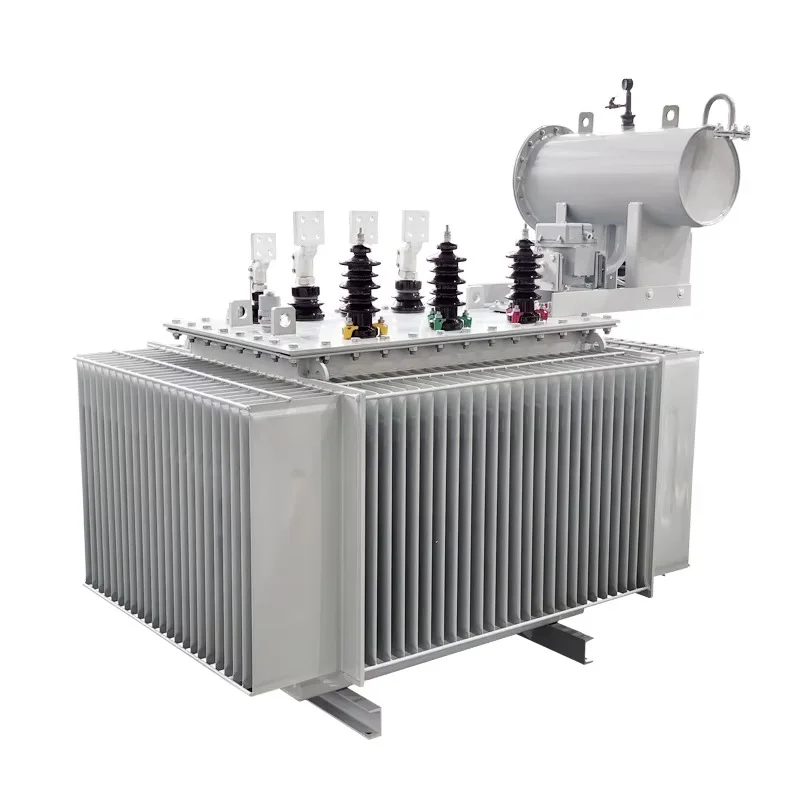
An oil-cooled transformer with oil pillow is a type of oil immersed transformer that includes an oil expansion device mounted on top of the tank. This pillow, often called an oil conservator, allows the transformer to adjust to temperature variations, ensuring that insulating oil maintains optimal pressure and volume.
This design not only enhances transformer safety but also reduces maintenance risks. The result is a sealed oil cooled transformer capable of delivering reliable power even under heavy or fluctuating loads.
Core Features
- Oil pillow integration – provides automatic oil level adjustment and expansion.
- Advanced cooling system – oil immersion ensures efficient thermal regulation.
- Durable tank design – resistant to pressure changes and environmental stress.
- Flexible voltage ratings – suitable for medium and high-voltage distribution.
- Improved insulation – oil acts as both coolant and dielectric barrier.
- Reliable operation – reduces downtime in industrial and utility networks.
Key Advantages
- Stable oil management – prevents oil overflow or vacuum inside the transformer.
- Enhanced efficiency – supports high load conditions without overheating.
- Extended lifespan – oil conservator reduces stress on seals and windings.
- Low maintenance costs – easy monitoring through oil level indicators.
- Adaptable – compatible with outdoor and indoor applications.
- Safety assurance – reduces the chance of internal faults caused by oil imbalance.
| Technical Parameters of 35kV Class S11 Series Oil-immersed Distribution Transformer | ||||||||||||
| Rated Capacity (kVA) | Voltage Combination (kV) | Connection Group Designation | Losses (kW) | No-Load Current (%) | Short-Circuit Impedance (%) | Weight(Kg) | OverallDimensions (mm) L(Length) ×B(Width) ×H(Height) | Gauge Longitudinal/ Transverse | ||||
| High Voltage | Low Voltage | No-Load | Load (75℃) | Weight of Core and Windings | Oil Weight | Total Weight | ||||||
| 30 | 35 36.5 38.5 | 0.4 | Yyno Dyn11 | 0.14 | 0.89/0.84 | 1.7 | 6.5 | 165 | 230 | 580 | 1320×550×1550 | 550/550 |
| 50 | 0.17 | 1.21/1.15 | 1.6 | 230 | 265 | 730 | 1360×700×1680 | |||||
| 80 | 0.22 | 1.80/1.71 | 1.7 | 310 | 310 | 870 | 1395×730×1730 | |||||
| 100 | 0.23 | 2.01/1.92 | 1.4 | 370 | 340 | 1000 | 1440×760×1810 | |||||
| 125 | 0.27 | 2.38/2.26 | 1.4 | 440 | 380 | 1120 | 1450×800×1940 | 660/660 | ||||
| 160 | 0.29 | 2.82/2.69 | 1.3 | 540 | 415 | 1360 | 1470×800×2910 | |||||
| 200 | 0.34 | 3.33/3.16 | 1.2 | 635 | 455 | 1540 | 1500×800×2050 | |||||
| 250 | 0.41 | 3.95/3.75 | 1.1 | 725 | 490 | 1745 | 1530×830×2090 | |||||
| 315 | 0.49 | 4.76/4.53 | 1.1 | 825 | 525 | 1910 | 1550×870×2150 | |||||
| 400 | 0.58 | 5.75/5.47 | 1.0 | 980 | 595 | 2220 | 1600×940×2200 | 820/820 | ||||
| 500 | 0.69 | 6.92/6.58 | 1.0 | 7210 | 680 | 2(340 | 1750×1000×2280 | |||||
| 630 | 0.83 | 7.88 | 0.9 | 1110 | 800 | 3175 | 2130×950×2400 | |||||
| 800 | 0.98 | 9.41 | 0.8 | 1625 | 850 | 3595 | 2210×1075×2450 | |||||
| 1000 | 1.15 | 11.54 | 0.8 | 7955 | 965 | 4260 | 2250×1090×2630 | |||||
| 1250 | 1.41 | 13.94 | 0.7 | 2250 | 1130 | 4835 | 2210×1740×2690 | 1070/1070 | ||||
| 1600 | 1.70 | 16.67 | 0.6 | 2890 | 1260 | 5995 | 2250×2145×2700 | |||||
| 2000 | 2.09 | 20.43 | 0.5 | 3070 | 1330 | 6445 | 2320×2170×2750 | |||||
| 2500 | 2.52 | 21.85 | 0.5 | 3555 | 1390 | 7080 | 2340×2180×2510 | |||||
| Note: | ||||||||||||
| 1.The high voltage can provide a voltage regulation range of±5%or±2×2.5%.(The provided outline dimensions are for model selection reference only,and the final dimensions shall be subject to the product outline drawing.) | ||||||||||||
| 2.The load loss values above the diagonal in the table are applicable to the Dyn11 connection group,and the load loss values below the diagonal are applicable to the Yyn0 connection group. | ||||||||||||
Applications
The oil expansion tank transformer is widely used across industries:
- Utility substations – ensuring grid stability.
- Heavy industries – supporting continuous operations in steel, mining, and chemical plants.
- Renewable energy – wind and solar farms requiring stable transformers.
- Commercial complexes – hospitals, data centers, and shopping malls.
- Transport infrastructure – railway power systems and metro networks.
| Technical Parameters of 35kV Class S9 Series Oil-immersed Power Transformer | |||||||||||||
| Rated Capacity (KVA) | Voltage Combination (kV) | Connecfion Group Designaion | Losses (kW) | No-Load Current (%) | Short-Circut Impedance (%) | Weight(Kg) | Overall Dimensions (mm) L(Length) ×B(Width) ×H(Height) | Gauge Longitudinal/ Transverse | |||||
| High Voltage | High-voltage tapping range(%) | Low Voltage | No-Load | Load (75℃) | Weight of Core and Windings | Oil Weight | Total Weight | ||||||
| 200 | 35 | ±5 | 3.15 6.3 10.5 | Yd11 | 0.43 | 3.30 | 1.55 | 6.5 | 610 | 365 | 1310 | 1240×1270×1680 | 660/660 |
| 250 | 0.52 | 3.96 | 1.4 | 670 | 370 | 1405 | 1290×1280×1680 | ||||||
| 315 | 0.61 | 4.77 | 1.4 | 825 | 440 | 1685 | 1300×1350×1840 | ||||||
| 400 | 0.75 | 5.76 | 1.3 | 920 | 530 | 1910 | 2020×940×1870 | 820/820 | |||||
| 500 | 0.87 | 6.93 | 1.25 | 1110 | 610 | 2235 | 2150×1000×1920 | ||||||
| 630 | 1.04 | 8.28 | 1.10 | 1215 | 630 | 2420 | 2260×1060×1920 | ||||||
| 800 | 1.23 | 9.90 | 1.00 | 1540 | 750 | 3050 | 2330×1080×2010 | ||||||
| 1000 | 1.44 | 12.15 | 1.00 | 1795 | 835 | 3440 | 2390×1100×2060 | ||||||
| 1250 | 1.76 | 14.67 | 0.90 | 1960 | 900 | 3860 | 2450×1210×2090 | ||||||
| 1600 | 2.12 | 17.55 | 0.80 | 2275 | 1025 | 4540 | 2475×1230×2300 | ||||||
| 2000 | 2.72 | 19.35 | 0.70 | 2560 | 1050 | 4960 | 2380×2010×2300 | ||||||
| 2500 | 3.20 | 20.70 | 0.60 | 3390 | 1245 | 5730 | 2460×2150×2400 | 1070/1070 | |||||
| 3150 | 35~ 38.5 | 3.80 | 24.30 | 0.56 | 7.0 | 3785 | 1500 | 7600 | 2550×2220×2420 | ||||
| 4000 | 4.52 | 28.80 | 0.56 | 4690 | 1790 | 8500 | 2670×2390×2510 | ||||||
| 5000 | 5.40 | 33.03 | 0.48 | 5570 | 2015 | 9790 | 2870×2450×2750 | ||||||
| 6300 | 6.56 | 36.90 | 0.48 | 7.5 | 7380 | 2460 | 12620 | 3100×2580×2950 | 1475/1475 | ||||
| 8000 | 35~ 38.5 | ±2×2.5 | 3.15 3.3 6.3 6.6 10.5 11 | Ynd11 | 9.00 | 40.50 | 0.42 | 8870 | 2650 | 14100 | 3250×2680×3150 | ||
| 10000 | 10.88 | 47.70 | 0.42 | 10020 | 2930 | 16500 | 3320×2720×3230 | ||||||
| 12500 | 12.60 | 56.70 | 0.40 | 8.0 | 12880 | 3710 | 19780 | 3410×2950×3410 | |||||
| 16000 | 15.20 | 69.30 | 0.40 | 16120 | 4280 | 23950 | 3520×3180×3570 | ||||||
| 20000 | 18.00 | 83.70 | 0.40 | 18580 | 5230 | 29600 | 3730×3560×3990 | ||||||
| 25000 | 21.28 | 99.00 | 0.32 | 22970 | 6370 | 25350 | 4110×4120×4220 | 2040/2040 | |||||
| 31500 | 25.28 | 118.80 | 0.32 | 27600 | 7740 | 41900 | 4760×4570×4390 | ||||||
Installation & Maintenance
Installation steps:
- Place the transformer on a level, vibration-free foundation.
- Securely connect oil pillow equipment and check all seals.
- Fill the oil conservator to the recommended level.
- Test grounding, insulation, and cooling systems before operation.
Maintenance tips:
- Regularly monitor oil level through the pillow indicator.
- Conduct oil testing for dielectric strength every 12–18 months.
- Inspect gaskets and bushings for leaks or pressure issues.
- Schedule infrared scans to detect thermal irregularities.
How to Choose the Right Oil-Cooled Transformer with Oil Pillow
When selecting, consider:
- Capacity & rating – match load demand and grid voltage.
- Type of oil conservator – sealed vs. breathing oil pillow designs.
- Cooling class – ONAN (natural cooling) or ONAF (forced cooling).
- Efficiency standards – high-efficiency models reduce power losses.
- Application environment – outdoor installations may need extra sealing.
- Manufacturer certification – ensure compliance with IEC/ANSI standards.
FAQ
What is the purpose of the oil pillow in a transformer?
It acts as an expansion device, maintaining stable oil levels during temperature changes.
How does an oil pillow improve transformer safety?
It prevents vacuum conditions and oil leakage, reducing the risk of electrical faults.
Can this equipment be used in outdoor environments?
Yes, with protective sealing, it operates efficiently in outdoor substations and plants.
How often should the oil level in the pillow be checked?
Monthly inspections are recommended, especially in high-load systems.
Is an oil pillow transformer more durable than sealed designs?
Yes, because it reduces internal pressure and extends component lifespan.
Request Quote
Tell us your specifications, quantity, or application scenario and we will reply with a tailored quote.