Can a 480V to 120V control transformer give you 120/240V?
Published: Author: Hairui Electric
In most industrial panels, a standard 480V to 120V control transformer is designed to provide a single 120V secondary for control power, not a 120/240V split‑phase system. You can only get 120/240V from it if the secondary is specifically wound and brought out as 120/240V (with a center tap), or if you add an additional transformer designed for split‑phase output.
Can You Get 120/240V from a 480V to 120V Control Transformer?
When you are designing or purchasing an industrial control panel, the question comes up quickly: “I already have a 480V to 120V control transformer in the cabinet—can I also get 240V or even 120/240V from it?”
The short answer for most standard control transformers is no. They are built to supply a single low‑voltage control circuit (typically 120V or 24V), not a full 120/240V distribution system for receptacles, lighting, or small machinery. But there are a few exceptions and workarounds worth understanding before you finalize your BOM or send a purchase order.
If at any point you realize you need a dedicated 480V to 120V control transformer or a 480V to 120/240V transformer, do not hesitate to send a quick RFQ with your voltage, VA rating, and mounting requirements—clear specs save a lot of back‑and‑forth in procurement.
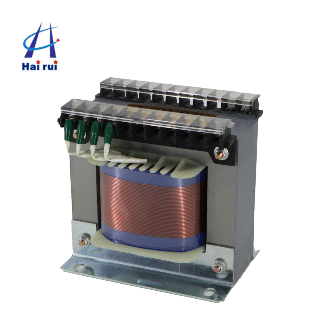
In many plants, a 480V to 120V control transformer is the quiet workhorse in every MCC, VFD enclosure, or OEM machine. Its role is simple: take a relatively high line voltage (often 480V) and step it down to a safer, more manageable level (commonly 120V or 24V) for relays, contactors, PLC I/O, and indicator lights.
A typical industrial control transformer has:
A primary winding connected to the line side, often with taps for 208/240/277/480/600V.
A secondary winding supplying control power, such as 120V, 24V, or a combination like 24/120V.
The basic relationship is defined by the turns ratio. For a 480V to 120V unit, the turns ratio is 4:1, meaning the primary has roughly four times as many turns as the secondary. That is what gives you a stable 120V control supply when the primary sees 480V.
This design is optimized for:
Stable low‑voltage control power
Short‑circuit and inrush performance suitable for coils and auxiliary devices
Compact size (machine tool transformers, motor control transformers, DIN rail control transformers, etc.)
What it is not optimized or configured for, by default, is delivering a 120/240V split‑phase system with a neutral, the way a building service transformer does.
Why You Usually Cannot Get 120/240V from a 480V to 120V Control Transformer
To understand why you normally cannot pull 120/240V from a plain 480V→120V JBK3 Machine Tool control transformer, it helps to compare what you have versus what you actually need.
Voltage and winding configuration differences
A standard control transformer has one secondary winding with two terminals (X1 and X2) that give you a single output voltage, such as 120V. There is no center tap brought out, so there is no way to “split” that secondary into two 120V legs that are 180° apart with a neutral in the middle, which is what a 120/240V split‑phase system requires.
By contrast, a 120/240V split‑phase transformer has a secondary arranged as 120‑0‑120. The 0V point is the grounded neutral; from each hot leg to neutral you get 120V, and between the two hots you get 240V. That configuration is intentionally designed into the transformer winding, and the manufacturer brings out three secondary terminals.
Here is a simple comparison:
Feature
480V→120V Control Transformer
480V→120/240V Distribution‑Type Transformer
Primary nominal voltage
480V (often with taps)
480V (may also have taps)
Secondary nominal voltage
Single 120V or 24V
120/240V split‑phase (120‑0‑120)
Secondary terminals
Typically X1–X2 only
X1–X2–X3 (center tap neutral)
Typical application
Control power, PLC, coils
Branch circuits, receptacles, small loads
Neutral conductor available
Only if one side is grounded
True neutral at center tap
Designed for 120/240V split‑phase?
No
Yes
Even if you try to “get clever” and ground one side of the 120V secondary, you still do not have two 120V legs 180° apart; you simply have a single 120V circuit with a grounded leg and a hot leg. There is no 240V between two hots because there is only one hot.
Code considerations and safety
There is also a code and safety angle. When the primary exceeds 300V, the secondary of a 480V to 120V transformer inside a control panel has specific grounding and bonding requirements. Common practice is to bond one side of the secondary (usually X2) to ground and treat that as the grounded conductor for the control circuit. This is still a single 120V control circuit, not a 120/240V distribution system.
Using that same small control transformer to feed receptacles or mixed branch circuits at 120/240V would usually violate design intent, overload the VA rating, and risk non‑compliance with local codes and standards. For B2B buyers and engineers, that is a non‑starter.
If your project spec or AHJ requires a 120/240V system derived from a 480V supply, plan for a transformer that is explicitly rated and labeled for 480V primary and 120/240V secondary, not a simple control power transformer. When in doubt, always send drawings and load schedules for review before ordering.
Alternatives If You Really Need 120/240V from a 480V System
So what should you do if you have a 480V distribution and need both 120V and 240V? You have three main paths, and your choice depends on load type, power level, and panel space.
1. Use a dedicated 480V to 120/240V transformer
The cleanest solution is to specify a single‑phase transformer with 480V primary and 120/240V secondary. These units are designed like the pole‑mounted or pad‑mounted distribution transformers that supply residential 120/240V split‑phase.
You then:
Land 480V on the primary according to the wiring diagram.
Use the three secondary terminals (120‑0‑120) to build a small 120/240V panelboard.
This allows:
120V loads (L1–N and L2–N).
240V loads (L1–L2).
Such transformers usually have higher kVA ratings than control transformers and are sized for branch‑circuit loading rather than just a few coils. For buyers, typical search terms include “480V to 120/240V dry‑type transformer”, “single‑phase distribution transformer 480–120/240”, or “step‑down transformer 480 to 120/240V, NEMA 3R”.
2. Combine a 480V→120V transformer with an additional 120V→120/240V unit
Another approach, especially in retrofit situations where the 480V to 120V control transformer is already fixed in the design, is to:
Use the existing 480V to 120V transformer for control circuits only.
Add a separate transformer that takes 120V as its primary and outputs 120/240V split‑phase (120‑0‑120).
In this architecture, the 480V network feeds a control transformer, and then a secondary transformer generates a small 120/240V system for special loads. This is commonly seen in off‑grid and inverter systems, where a 120V inverter feeds a split‑phase autotransformer to create 120/240V.
From a procurement angle, this means specifying two items:
A control power transformer (480V to 120V) with VA sized for your control panel.
A split‑phase transformer or autotransformer with 120V primary and 120/240V secondary sized to the downstream load.
3. Use a 3‑phase system or multiple transformers for balanced loads
In some facilities, it may be more efficient to:
Keep most loads at 480V or 240V three‑phase, and
Only step down where truly needed for 120V receptacles, IT loads, or small equipment.
In those cases, you may specify a 480V to 208Y/120V three‑phase transformer for panelboards, and keep the 480V to 120V control transformer dedicated to machine controls. The cost per kVA and conductor sizing can often be optimized this way.
If you are not sure which topology fits your plant, send your line voltage, fault level, and load list; a vendor or consulting engineer can quickly suggest a standard transformer configuration.
Key Selection Factors for a 480V to 120V Control Transformer
Even if you decide not to use the control transformer for 120/240V, you still want to choose the right 480V to 120V control transformer. For engineers and buyers, the usual checklist looks like this.
Voltage and taps
Most modern control transformers support multiple primary voltages:
208V, 240V, 277V, 480V, and sometimes 600V on the line side.
Secondary options like 120V, 24V, or 24/120V combinations.
This flexibility is critical for OEMs who sell into multiple markets and for integrators who standardize on one control transformer model across several panel designs.
VA rating and inrush
Control circuits can have high inrush currents when contactors or solenoids energize. Proper sizing by VA rating is essential to avoid nuisance voltage dips and premature transformer failure. Standards and manufacturer charts are often used to size for:
Total steady‑state VA (sum of coils, lamps, electronics).
Inrush VA for simultaneous coil energization.
Oversizing slightly is common in B2B projects; the cost delta is often small compared to the risk of downtime.
Mounting and form factor
For panel builders, mounting style matters:
Back‑panel mount and base‑mount for traditional MCCs.
DIN rail control transformers for compact OEM and machine‑tool designs.
The footprint and wiring space can influence enclosure size, which in turn affects cost and delivery. Clearly specifying mounting in the RFQ will help vendors quote the right series.
Here is a quick overview of control transformer selection aspects:
Parameter
Typical Options / Notes
Primary voltages
208/240/277/480/600V single‑phase taps
Secondary voltages
120V, 24V, or 24/120V combinations
VA ratings
From small tool transformers to multi‑kVA for dense MCC panels
Mounting
Back‑panel, base‑mount, DIN rail
Application
Motor control, PLC, HMI, auxiliary machines
If you already know your control load and supply voltage, you can send those details directly in an inquiry and receive a matched 480V to 120V control transformer recommendation.
In short, if your design calls for 120/240V, do not rely on a standard 480V to 120V control transformer to do double duty. Instead, specify either a dedicated 480V to 120/240V transformer or a combination of a control transformer plus a split‑phase transformer. When you are ready, share your line voltage, required output (120V only or 120/240V), and VA rating, and you can receive a tailored transformer proposal that fits both your engineering and procurement targets.
FAQ
u003cstrongu003eCan I get both 120V and 240V from a standard 480V to 120V control transformer?u003c/strongu003e
Usually no. A standard 480V to 120V control transformer has only a single 120V secondary, not a 120/240V split‑phase winding.
u003cstrongu003eIf I ground one side of the 120V secondary, do I then have 120/240V?u003c/strongu003e
No. Grounding one side of the 120V secondary just creates a grounded conductor and a hot conductor for a single 120V circuit; it does not create two 120V legs 180° apart or a 240V potential between them.
u003cstrongu003eWhat transformer do I need for a true 120/240V split‑phase system from 480V?u003c/strongu003e
You need a transformer whose secondary is explicitly wound and labeled as 120/240V (120‑0‑120), typically specified as 480V primary and 120/240V secondary.
u003cstrongu003eCan an autotransformer create 120/240V from 120V if I already have a 480V to 120V transformer?u003c/strongu003e
Yes, that is a common solution: use the 480V to 120V transformer for isolation and then a 120V‑in, 120/240V‑out autotransformer to create the split‑phase system.
u003cstrongu003eAre control transformers supposed to feed receptacles or lighting loads?u003c/strongu003e
Not typically. Control transformers are designed for control circuits, not for general‑purpose receptacles or lighting branch circuits, which should be served by properly sized distribution transformers and panels.
u003cstrongu003eWhat information should I include when sending an RFQ for a 480V to 120V control transformer?u003c/strongu003e
Include primary voltage, secondary voltage, VA rating, frequency, mounting style, and environmental (NEMA/IP) requirements so suppliers can quote a suitable control or control‑power transformer quickly.
Have you ever looked inside a control cabinet and wondered why the JBK3 220/24V control transformer for PLC power is there, instead of just running everything straight off the main line? As a transformer sales engineer, I get asked this all the time. The short answer is: safety, isolation, and stable low‑voltage control power. The slightly longer answer […]
Overloading a JBK3 industrial low‑voltage machine control transformer is one of the fastest ways to turn a perfectly good control power supply into a warm‑to‑toasty anxiety trigger. As a transformer seller, I’ve seen more than a few machines shut down because someone simply “plugged in one more relay” without thinking about VA. In this post, […]
If you are an industrial buyer, panel builder, or automation engineer, you have probably seen “control transformer” and “JBK3 control transformer” listed side by side in a catalog. At first glance they look the same. But when you start wiring a machine‑tool panel or an industrial control cabinet, the difference really matters. In this article, […]