When a line stops because one tiny contactor coil doesn’t pull in, people start blaming everything – PLC, relays, even the electrician. Very often, the real “boss” behind the problem is the Control Power Transformers JBK3. In this article, I’ll walk you through what a control power transformer is, how to wire it, how to size it, and when it makes sense to choose a JBK3 model for your B2B projects.
What Is a Control Power Transformers JBK3?
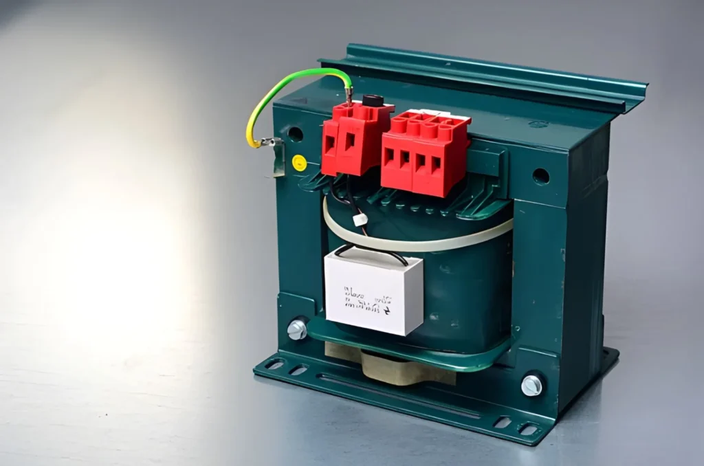
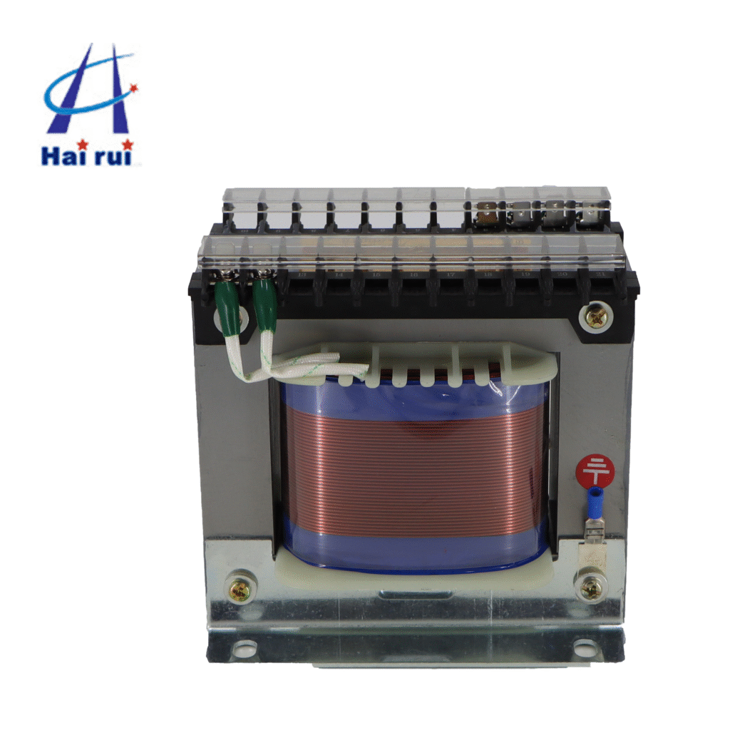
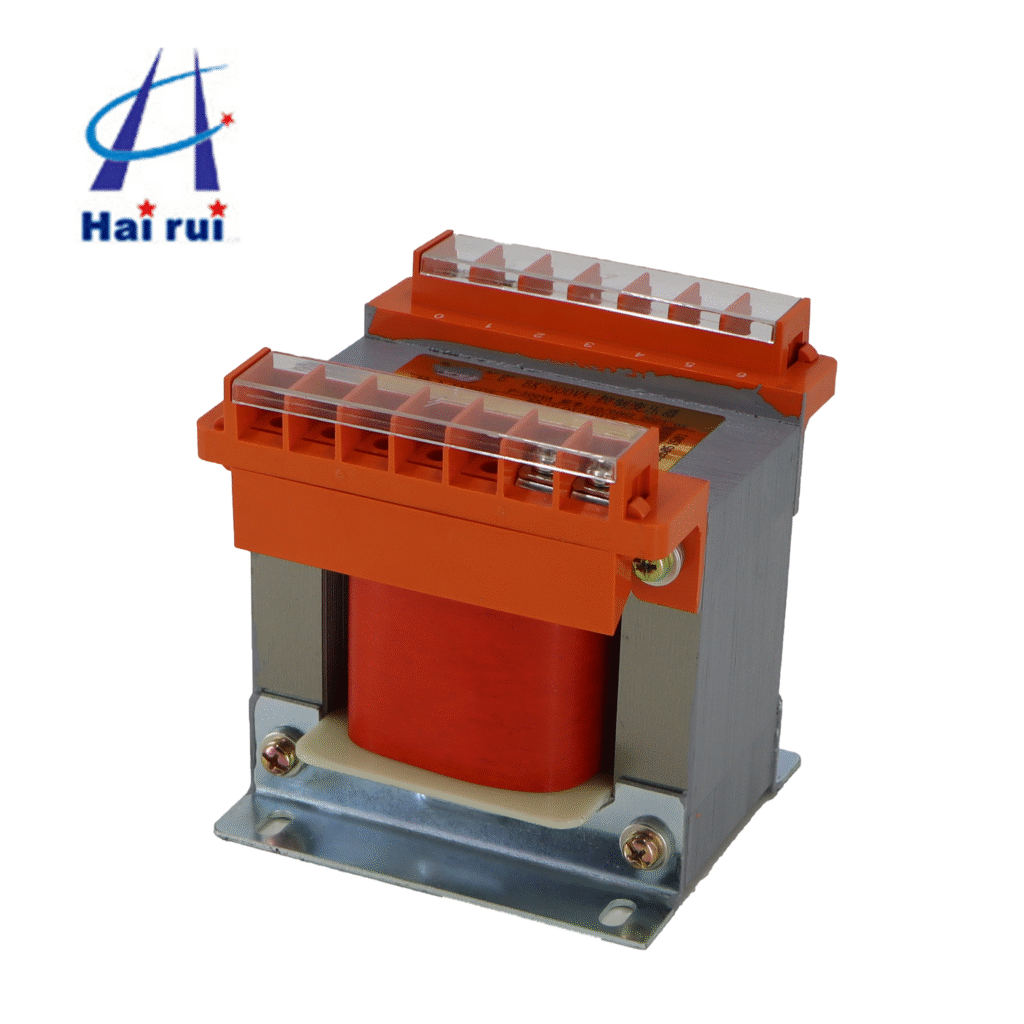
A control transformers is a single‑phase transformer that steps down your main AC line voltage to a safer, stable voltage for control circuits. Think of it as the “power bank” for relays, contactors, PLC input modules, indicator lamps, and small auxiliary loads.
In typical industrial systems, the main bus might be 380 V, 400 V, 415 V, 440 V or 480 V, while control circuits often use 24 V, 36 V, 110 V or 220 V for easier insulation coordination and safer maintenance. The control power transformer takes care of that conversion and provides electrical isolation between the high‑voltage side and the low‑voltage control side.
A good Control Power Transformers JBK3 does three key jobs:
Steps down voltage from line level to control level.
Provides isolation, improving safety and reducing interference.
Maintains relatively stable output even when the supply has minor fluctuations.
For buyers, this part often looks small on the BOM. But if the control power transformer is undersized, the entire machine can become unstable, especially at startup when multiple coils energize together.
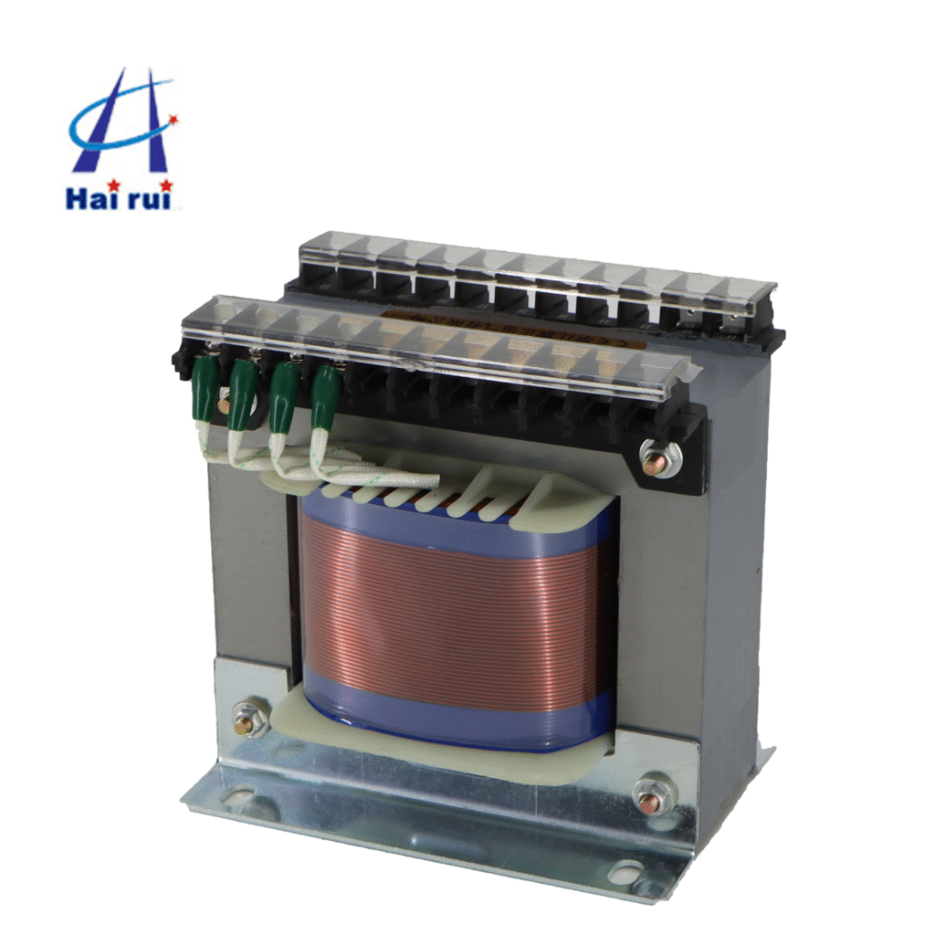
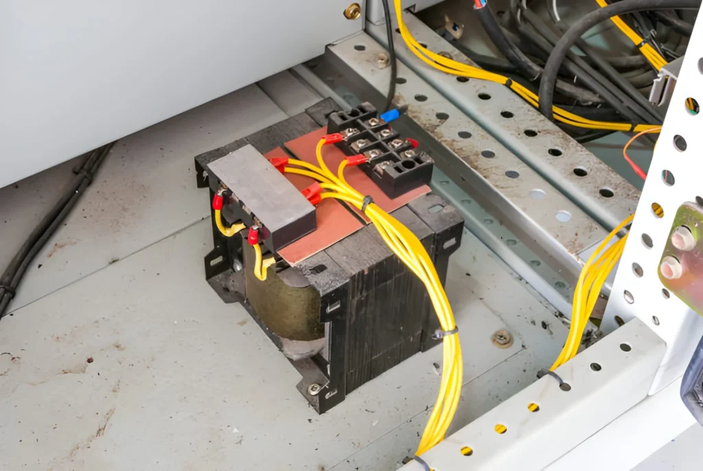
The JBK3 series is a family of machine tool control transformers designed for AC 50/60 Hz, single‑phase applications. It’s commonly used as a control power source in CNC machines, lathes, milling machines, packaging equipment, and general automation cabinets.
Main features of JBK3
Typical features of JBK3 control transformers include:
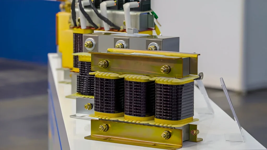
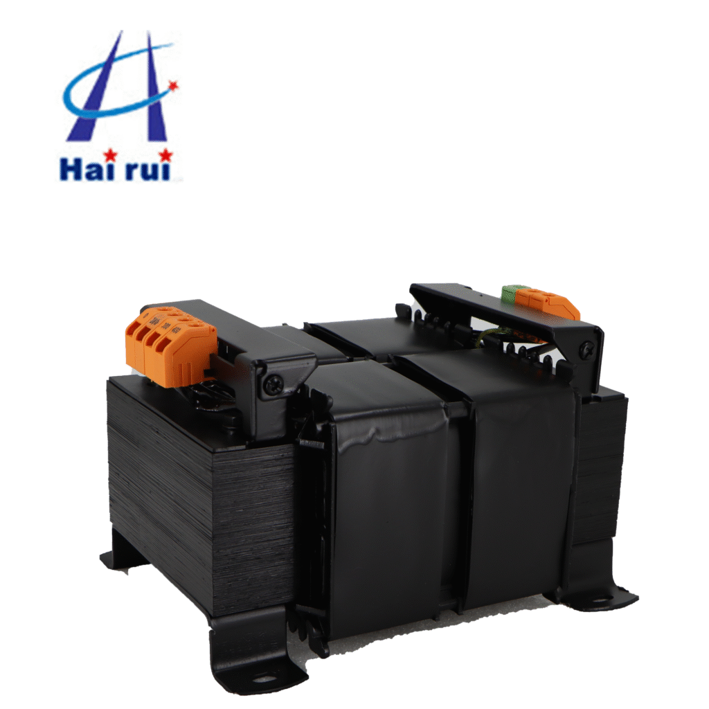
Single‑phase, laminated core construction for compact size and good efficiency.
Rated frequency: 50 Hz or 60 Hz.
Primary voltage options: often multiple taps covering common industrial voltages (for example 200 V, 220 V, 230 V, 380 V, 400 V, 415 V, 440 V, 460 V depending on the specific design).
Secondary voltage options: commonly up to 220 V, with popular combinations like 6 V, 12 V, 24 V, 36 V, 110 V, 127 V, 220 V. Many models allow dual or multi‑secondary outputs (for control circuits and signal lamps).
Rated capacity (VA): a wide range from around 40 VA up to 2500 VA or similar, depending on the series completeness.
Terminal types: screw or pressure‑type terminals, sometimes plug‑in style, designed for quick cabinet wiring.
Typical applications: machine tools, control cabinets, lighting circuits, control signal circuits, and other low‑power auxiliary systems.
Typical technical table for JBK3
Below is a simplified example of what the technical table for Control Power Transformers JBK3 series may look like. Exact values depend on the specific manufacturer, but this structure is close to what you’ll see in a datasheet.
Parameter
Typical JBK3 Range/Value
Comment
Phase
Single‑phase
Standard for control circuits
Frequency
50 / 60 Hz
Works in most grids
Primary voltage
Up to around 500–660 V (multi‑tap options)
Supports common industrial line voltages
Secondary voltage
6–220 V, single or multiple windings
For control, signal, auxiliary circuits
Rated capacity
Approx. 40 VA – 2500 VA (series dependent)
From small panels to large machines
Insulation class
Typically Class B or F
Temperature stability for industrial use
Mounting
Foot / base mounting in control cabinets
For panel or back‑plate installation
Terminals
Screw / pressure / plug‑type
For quick wiring in MCC and machine panels
If you need a quick summary: JBK3 is basically a versatile, standardized control power transformer family that can be reused across multiple machine designs.
How to Wire a Control Power Transformer (Including JBK3)
Let’s be honest: wiring is where things get interesting. Fortunately, control power transformers follow simple rules if you respect terminal markings and wiring diagrams.
Basic terminal logic
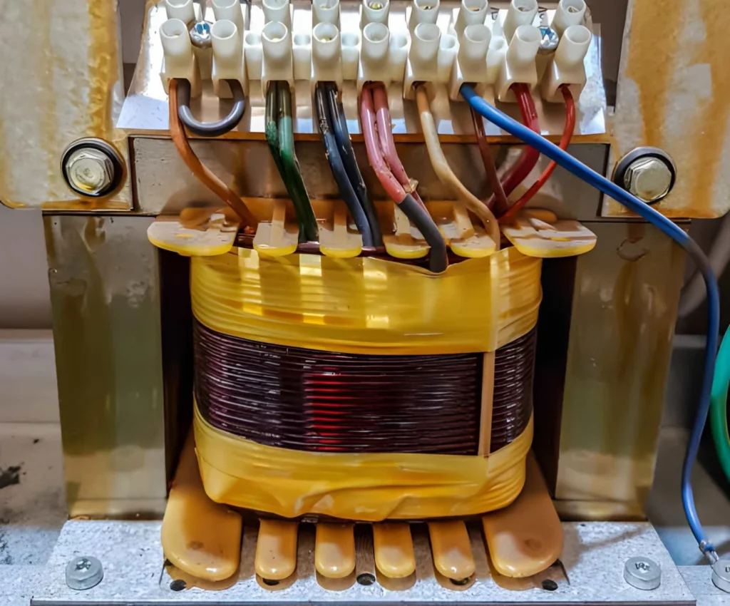
On most control power transformers, you’ll see:
Primary (input) terminals, often labeled as H1, H2 (or P1, P2) and extra taps for different voltages.
Secondary (output) terminals, often labeled as X1, X2, X3, X4, depending on whether you have single or multiple secondaries.
Multi‑tap primaries let you adapt the transformer to different supply voltages by choosing the correct combination of primary terminals. Multi‑secondary outputs allow you to feed different circuits (for example, one secondary for control coils and another for indicator lamps).
Step‑by‑step wiring procedure
Here is a practical wiring procedure you can include in internal instructions or hand to the panel shop.
Wire secondary to the control devices (relays, PLC PSU, lamps, etc.).
Distributes control power properly
8
Check torque on all terminal screws.
Avoids overheating and loose connections
9
Energize and measure secondary voltage at no load.
Verifies the wiring before full operation
10
Add load gradually and recheck voltage stability.
Confirms correct operation under load
A common mistake is to assume “all primaries are the same” and simply feed whatever line voltage is available. For multi‑tap Control Power Transformers JBK3, you must follow the wiring diagram to bridge and connect the correct taps. For example, a JBK3 unit with taps for 380 V and 400 V will specify exactly which terminals to link and which ones receive the incoming line.
Grounding and protection
Always ground the core or metal frame according to your local electrical code.
Protect the primary with an appropriate circuit breaker or fuse.
Consider secondary fusing for sensitive control circuits to simplify troubleshooting and avoid burning wiring if a device fails.
If your maintenance team often works at night or in dark cabinets, consider specifying transformers with clearly printed terminal markings and labeled covers – it’s a small detail that can save a lot of time during breakdowns.
How to Select the Right Control Power Transformer (How to Choose, What to Choose)
Now let’s get to the part procurement teams love: how to select a model, how to size it correctly, and when the JBK3 series makes sense.
Determine input and output voltages
First, fix two simple questions:
What is your line voltage? (e.g., 380 V, 400 V, 415 V, 440 V, 460 V, 480 V)
What control voltage do you use? (e.g., 24 V, 36 V, 110 V, 127 V, 220 V)
Control power transformers must match both values. If your machines are sold to different countries, multi‑tap primaries are extremely useful. One JBK3 transformer model can cover several line voltages just by changing the primary wiring, avoiding redesign of the entire control circuit.
If you need two different control voltages, for example 220 V for contactor coils and 24 V for indicator lamps or sensors, select a JBK3 version with either:
Two secondaries with different voltages, or
A secondary designed with taps for multiple voltages.
Calculate required VA (sizing)
Sizing is where many control transformers are either over‑killed or under‑designed. A simple sizing process looks like this:
List all loads connected to the secondary:
Coils of contactors and relays (check inrush VA and holding VA).
Consider inrush: contactor and solenoid coils can draw several times rated VA during energization.
Add a safety margin, typically 20–50%, depending on how “busy” your control circuit is and whether many loads energize simultaneously.
Here is a simple guidance table:
Total Control Load (approx.)
Suggested Transformer Rating
Typical Scenario
Up to 30–40 VA
40 VA – 63 VA
Very small panel, a few relays and lamps
40–80 VA
100 VA
Small machine control panel
80–130 VA
160 VA
Medium panel, few contactors + PLC PSU
130–200 VA
250 VA
Typical CNC or packaging machine
200–320 VA
400 VA
Larger machine with several contactors
320–500 VA
630 VA
Heavy control panels or small line
Above 500 VA
800 VA and higher
Complex lines, many loads
You don’t have to hit the exact number. If your calculated load is 135 VA, it’s reasonable to choose a 160 VA or even 250 VA unit depending on your expansion plans.
Matching your calculation to JBK3 models
JBK3 series usually includes successive VA steps such as 40, 63, 100, 160, 250, 400, 630, 800, 1000, 1600, 2500 VA, or similar. Once you calculate your required VA:
Choose the next higher standard JBK3 rating.
Check that the selected model supports your desired primary and secondary voltages.
Confirm physical size and mounting dimensions fit your cabinet.
Here is an example of mapping:
Calculated Load
Selected JBK3
Comment
30 VA
JBK3‑40
Enough margin for small capacity increase
55 VA
JBK3‑63
Useful for small control boards
90 VA
JBK3‑100
Covers medium loads with some margin
130 VA
JBK3‑160
Typical small CNC or packaging machine
210 VA
JBK3‑250
Good for medium multi‑contactor panels
300 VA
JBK3‑400
Handles heavier inrush loads
450 VA
JBK3‑630
Suitable for larger and more complex panels
If you are not fully comfortable with the load calculation, you can always prepare a simple table of device types, quantities, and VA rating, then send it to a manufacturer for sizing support.
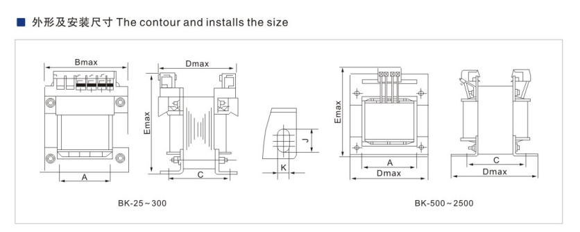
Check dimensions and mechanical details
JBK3 models get physically larger as VA rating increases. As a buyer or designer, you should:
Check length, width, height, and mounting hole spacing.
Confirm the transformer fits into the allowed space in the cabinet.
Decide if terminals will be accessible after installation.
Here is how you might compare dimension trends for planning (numbers are indicative):
JBK3 Rating
Physical Size Trend
Typical Use Case
40 / 63 VA
Very compact, low height
Tight panels, limited space
100 / 160
Small‑medium footprint
Standard machine control panels
250 / 400
Medium size
CNC, larger automatic machines
630 / 800
Larger, heavier
Lines with multiple loads
1000+
Large and heavy
Complex systems or multiple machines feed
If you have strict height or depth constraints, pass those numbers to your supplier at quotation stage and let them adapt the recommendation.
When Does a JBK3 Make the Most Sense?
You can of course use many different series of control power transformers, but JBK3 tends to shine in a few typical B2B scenarios.
Ideal scenarios for using JBK3
Machine tool builders and OEMs JBK3 offers a wide range of voltages and ratings, making it convenient for standardizing across a full machine family.
Export‑oriented control panels Multi‑tap primaries allow manufacturers to adapt the same panel design to different countries simply by changing the primary wiring.
Retrofit and replacement markets JBK3 is widely used and easy to match mechanically in retrofit situations where an old machine tool control transformer needs replacement.
Distributors and wholesalers Because JBK3 covers a wide VA range and common voltages, stocking a limited number of models can still cover many end‑user needs.
Comparison table: generic control transformer vs. JBK3
Feature
Generic Control Transformer
JBK3 Series Control Transformer
Primary voltage options
Often fixed, few options
Often multi‑tap, broad range
Secondary voltage options
Single or limited
Multiple combinations for control + lamps
Typical application focus
General control circuits
Machine tools and industrial automation
VA range
Narrow or brand‑specific
Wide range from small to large loads
Ease of panel standardization
Average
High, thanks to consistent series design
The more you want to standardize across projects, the more attractive a series like JBK3 becomes.
Control power transformers may not be the most glamorous components in your cabinet, but they quietly decide whether your machine starts smoothly or spends its time tripping contactors. A well‑selected, correctly wired JBK3 control transformer gives you stable control voltage, easier standardization, and fewer “mystery” breakdowns at inconvenient hours.
If you are planning a new machine series, upgrading existing panels, or building stock for distribution, it’s a good idea to prepare a simple specification sheet (input voltage, control voltage, VA rating, standards, and quantity) and send it to a professional control transformer supplier. They can help you choose the right JBK3 models and optimize cost, performance, and delivery time for your next project.
FAQ
What does a control power transformer actually do?
It converts high line voltage to a stable, lower voltage for control circuits and provides electrical isolation between power and control sides. This keeps relays, contactors, PLCs, and signal devices operating safely and reliably.
Is a JBK3 transformer only for machine tools?
No. While it is very popular in machine tool applications, JBK3 can also be used in general industrial control cabinets, small distribution panels, packaging machines, and other automation equipment requiring single‑phase control power.
How do I know which VA rating I need?
List all devices connected to the secondary, sum their VA, consider inrush for coils, and add a safety margin of 20–50%. Then pick the next higher standard JBK3 rating (for example 100 VA, 160 VA, 250 VA, 400 VA, 630 VA).
Can one JBK3 unit feed both control circuits and signal lamps?
Yes, as long as you choose a model with suitable secondary voltage(s) and enough VA capacity. Many designs allow sharing one secondary for multiple loads, or using separate secondary windings for different circuits.
How should I wire the primary of a multi‑tap JBK3?
Check your actual line voltage and the transformer wiring diagram. Select the corresponding taps, link any required terminals with copper links as shown, and then connect the line to the designated input terminals. Never guess; always follow the diagram.
What information should I send to a manufacturer when asking for a quote?
At minimum, include: primary voltage (and whether you need multi‑taps), secondary voltage(s), total VA or load list, frequency, working environment, quantity, and any special mounting or terminal requirements. With that, a manufacturer can quickly recommend a JBK3 model and pricing.
Buying a Control Transformer Prices sounds simple until you actually try to source one across borders. Suddenly, you are not just comparing a “price”—you are comparing standards, copper and steel exposure, certifications, lead time, logistics, payment terms, and how much customization a supplier is willing to do without turning your RFQ into a science project. […]
When you’re sourcing electrical components for your system, it’s common to wonder — “Can I use a general transformer instead of a control transformers?” At first glance, they seem quite similar. Both devices step voltage up or down, both rely on electromagnetic induction, and both come in similar enclosures. However, when it comes to reliability, efficiency, and […]
Ever wondered why a control panel or industrial machine often contains more than one type of transformer? If you’ve encountered both Control Transformers and isolation transformers on schematics and weren’t sure how they differ, this article will make it clear. Both play vital roles in electrical systems—but they’re not designed for the same purpose. Understanding their differences helps improve […]
We use cookies to enhance your browsing experience, serve personalised ads or content, and analyse our traffic. By clicking "Accept All", you consent to our use of cookies.