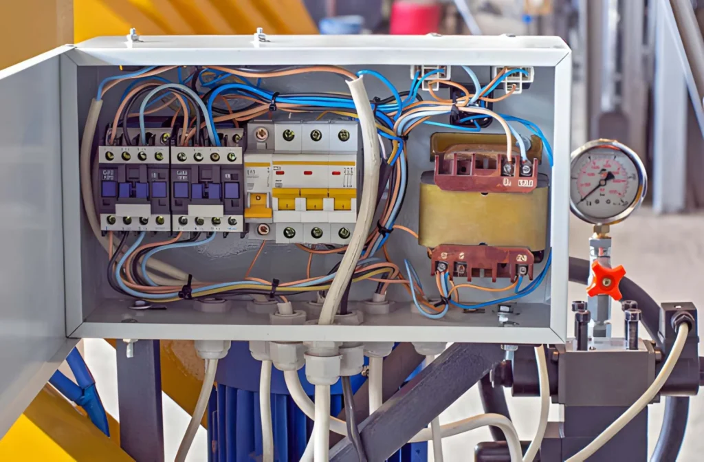
Overloading a JBK3 industrial low‑voltage machine control transformer is one of the fastest ways to turn a perfectly good control power supply into a warm‑to‑toasty anxiety trigger. As a transformer seller, I’ve seen more than a few machines shut down because someone simply “plugged in one more relay” without thinking about VA.
In this post, you’ll see not just theory, but how to actually connect, which JBK3 model to pick, and what to watch for on the panel. If you’re a procurement or engineering buyer choosing transformers for machine tools, automation lines, or control cabinets, this will help you avoid unnecessary failures and keep your suppliers happy—especially when you tell them, “No, we did not overload it this time.”
What “overloading” really means for a JBK3 control transformer
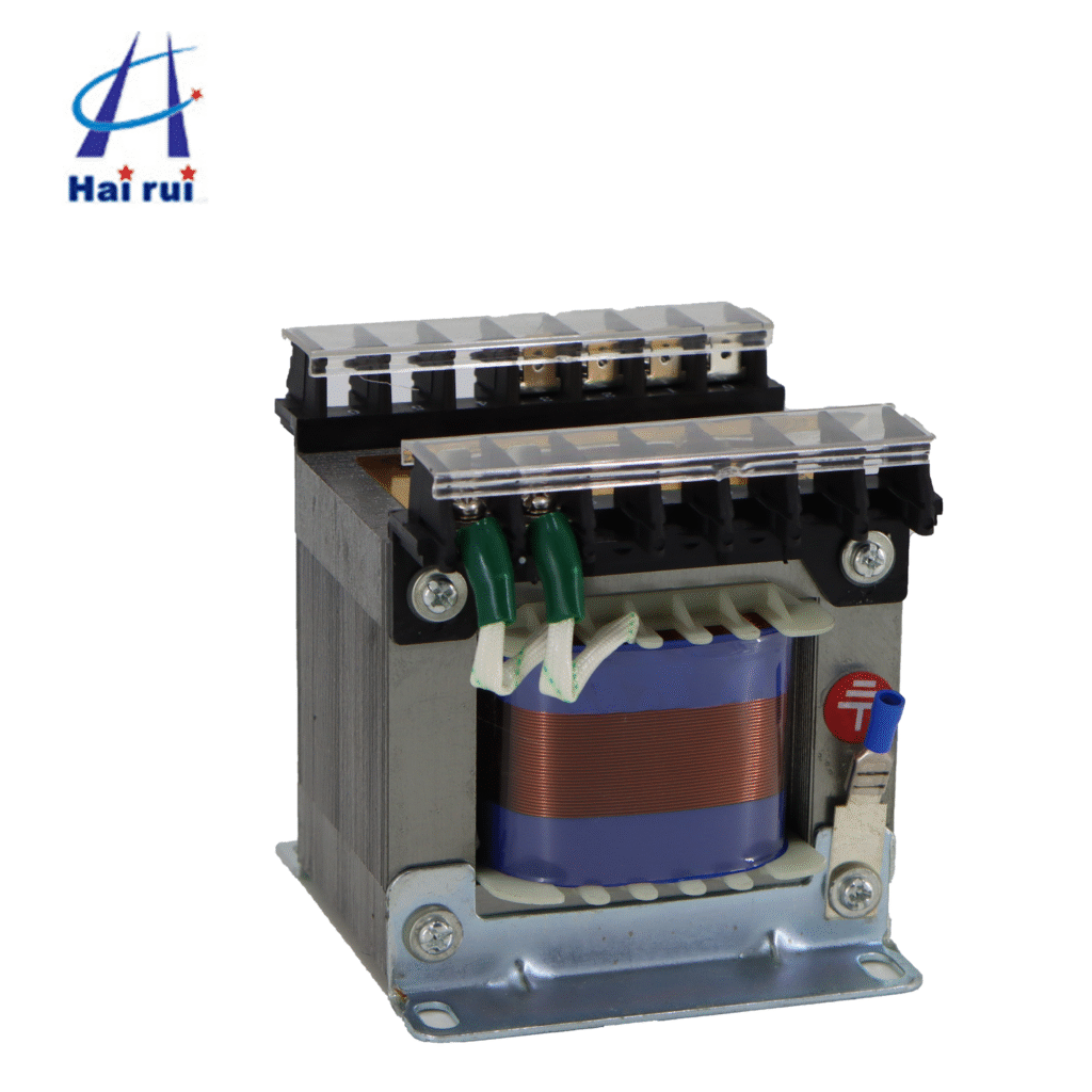
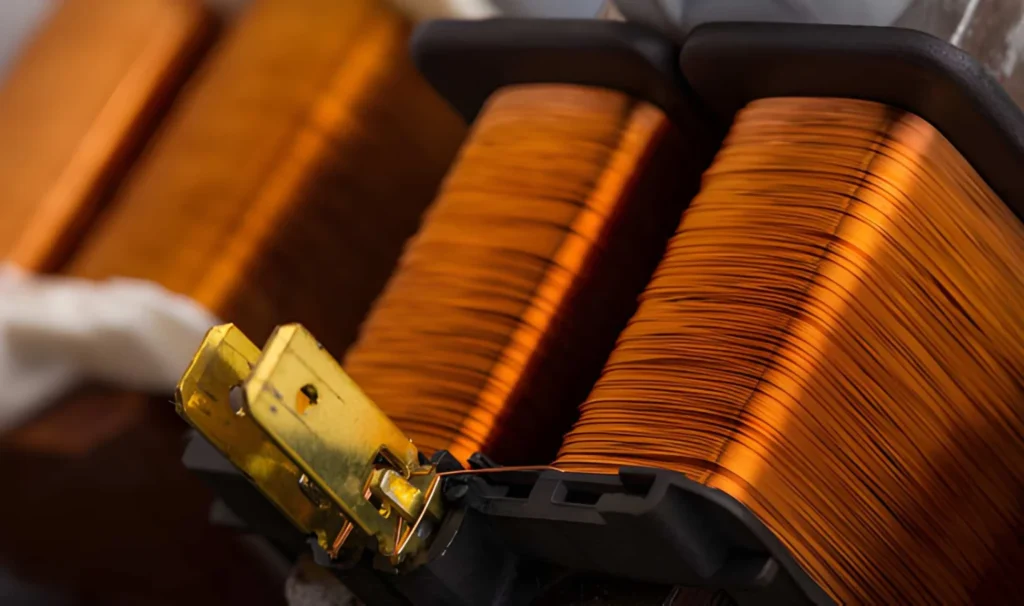
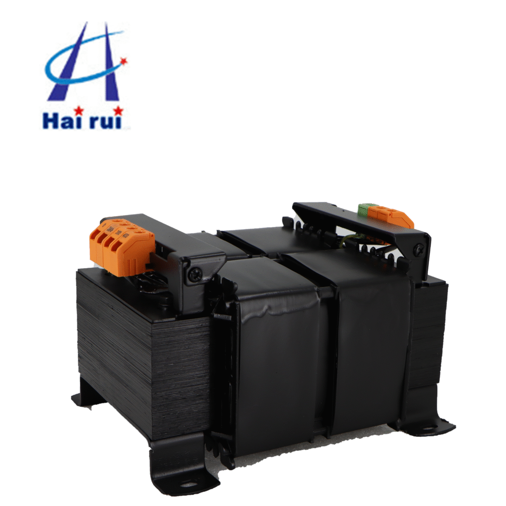
A JBK3 industrial low‑voltage machine control transformer is a single‑phase, dry‑type isolation transformer, typically used for control power, local lighting, signal lamps, and low‑voltage coils of contactors and relays.
Overloading happens when the total connected load (in VA or watts) exceeds the rated kVA/VA of the transformer, or when the heat‑rise conditions are worse than the design allows. This leads to:
Faster insulation aging and premature failure
Higher temperature rise and possible tripping of thermal protection
Reduced life expectancy and unplanned downtime
For a JBK3 industrial low‑voltage machine control transformer, the manufacturer’s rated VA, primary voltage, and secondary voltage are your hard limits—not “a little above” recommendations.
How to choose the right JBK3 model (not too small, not too big)
Picking the right JBK3 industrial low‑voltage machine control transformers model is the first defense against overloading. Here is a practical way to do it, suitable for B2B procurement and panel‑design buyers.
Collect your control‑load data
Start by listing every device that draws power from the control transformer:
Control relays, contactors, PLC power supplies
Pilot lights, indicator lamps, and small control‑circuit heaters
Small local work lights (if fed via the JBK3)
For each device, note:
Voltage (e.g., 24 VAC, 24 VDC, 110 VAC, 220 VAC)
Rated consumption in VA or watts
If only watts are given and the load is resistive (lamps, heaters), treat 1 watt ≈ 1 VA. For inductive coils (relay coils, contactor coils), use the VA rating from the datasheet, not the wattage printed on the device.
Apply a safety margin (B‑to‑B best practice)
Once you have the sum of all VA, add a safety margin. For machine‑tool control‑transformer applications, a widely accepted rule is:
Add 20–30% margin for future add‑ons, relay surges, and ambient temperature.
For example:
Total measured load: 200 VA
With 25% margin: 200 × 1.25 = 250 VA
So you should select at least a JBK3‑250 model or higher, depending on your exact voltage and wiring scheme.
JBK3 model‑size reference table
Here is a simplified performance‑oriented comparison table for common JBK3 industrial low‑voltage machine control transformers. This table helps you quickly narrow down the right transformer for your control‑load level.
Model (JBK3‑x)
Typical rated VA
Typical input voltage range (V)
Typical secondary voltages (V)
Best‑fit control‑load range (VA)
JBK3‑40
40
220–380–440
6, 24, 36, 110, 220
25–35 VA (small CNC panels, basic relays)
JBK3‑63
63
220–380–440
6, 24, 36, 110, 220
40–55 VA (small machines, simple control)
JBK3‑100
100
220–380–440
6, 24, 36, 110, 220
70–90 VA (mid‑size lathes, small PLC)
JBK3‑160
160
380–440
6, 24, 36, 110, 220
110–140 VA (automation cabinets, bigger relay banks)
JBK3‑250
250
380–440
6, 24, 36, 110, 220
170–230 VA (medium‑size PLC‑based machines)
JBK3‑400
400
380–440
6, 24, 36, 110, 220
280–360 VA (larger control panels, multiple PLCs)
JBK3‑630
630
380–440
6, 24, 36, 110, 220
440–570 VA (complex automation lines)
If your calculated load plus margin is close to the upper edge of a model’s range, jump to the next size. Over‑sizing by one step is much cheaper than unplanned downtime and transformer replacement.
If you’re sourcing for OEM machine builders or system integrators, you can also ask for JBK3‑series machine tool control transformers with multi‑tap primaries (e.g., 380V, 400V, 415V, 440V) so one transformer fits multiple global voltage standards from the same panel design.
If you want, you can send me your project specs I’ll help you pick the right industrial JBK3 industrial low‑voltage machine control transformer model and quantity.
How to wire a JBK3 transformer correctly (not “just connect some wires”)
Even a perfectly sized JBK3 industrial low‑voltage machine control transformer can be overloaded if wiring is done wrong. Here is how to get it right in a way that’s easy for electricians and panel assemblers to follow.
Primary side: input connections and overcurrent protection
Typical JBK3 input: single‑phase, 50–60 Hz, up to 500 V or 660 V depending on the design, connected near the main MCCB or contactor.
On the primary side, you can do one of two things:
Use terminal blocks with screw‑type terminals directly on the JBK3
Use press‑fit or plug‑type connectors if the JBK3 model supports them
Make sure the primary conductor size matches the transformer’s full‑load current. For example:
A JBK3‑250 at 380 V primary draws about 0.66 A at full load (250 VA ÷ 380 V).
A JBK3‑630 at 380 V draws about 1.66 A (630 VA ÷ 380 V).
Use copper conductors rated for at least 1.25 times this current for continuous operation. For small control transformers like JBK3‑40–JBK3‑250, 1.5 mm² copper cable is usually sufficient (check local standards).
Overcurrent protection (fuse or breaker) on the primary side should comply with rules similar to those in NEC Article 450:
Primary overcurrent protection not exceeding 125% of full‑load primary current.
Secondary overcurrent protection (if separate) up to 250% of full‑load secondary current for low‑voltage control transformers.
If your local code or standards differ, treat this as a guideline and let your panel engineer or electrical designer confirm the exact fuse or breaker rating.
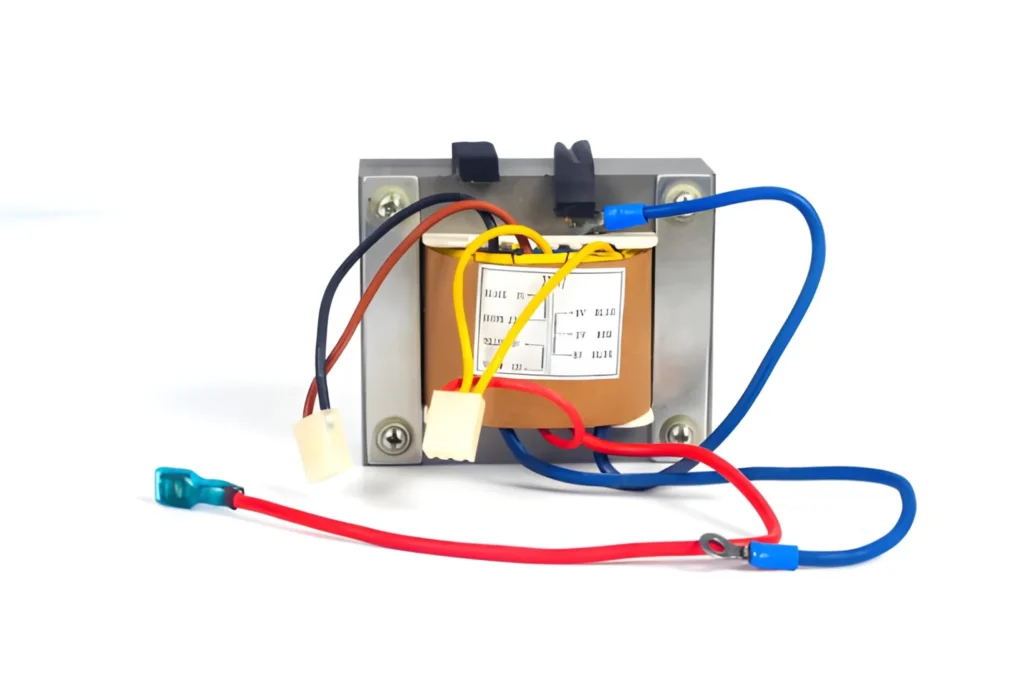
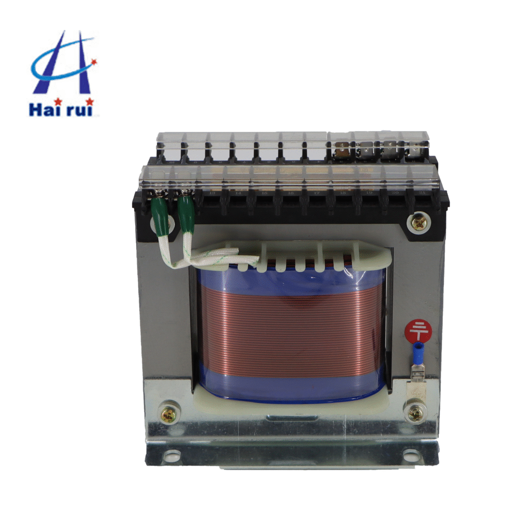
Secondary side: multiple taps, relays, and lamps
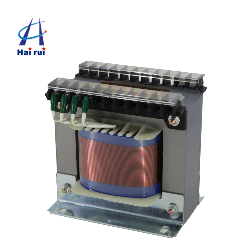
A JBK3 control transformer often has multi‑winding secondaries, for example:
220 V for larger contactor coils
24 V for small relays and PLC input power
36 V for some lighting or safety‑related circuits
Use the following wiring rules:
Do not mix VA loads randomly across taps. Allocate specific loads to each winding and keep a wiring diagram in the panel.
Never share a single 24 V tap with high‑VA loads (e.g., multiple large contactors) if the transformer is only rated for 24 V/20 VA.
Group low‑VA devices (indicator lamps, small relays) on a common 24 V rail, but keep a sum of their VA below 80% of the secondary’s rated VA.
Here is an example multi‑tap allocation table you can adapt for your own panels:
JBK3 model
Secondary 1 (V)
Secondary 2 (V)
Secondary 3 (V)
Example load group
JBK3‑160‑06
220 V
20–24 V
15 V
220 V contactor coils, 20–24 V relays, 15 V indicators
JBK3‑250‑14
220 V
20–24 V
15 V
220 V contactors, 20–24 V PLC module, 15 V pilot lights
JBK3‑450‑03
220 V
20–24 V
15 V
220 V contactor bank, 20–24 V PLC power, 15 V HMI panel light
Label every terminal clearly (e.g., “24 VAC CH1”, “220 VAC CT”). This helps maintenance teams avoid accidental overloading during upgrades.
Layout and installation tips to reduce real‑world overloading
Even a correctly sized and wired JBK3 industrial low‑voltage machine control transformer can suffer from “effective” overload if installation conditions are poor. Think of it like buying a good car engine and parking it inside a closed garage with no ventilation.
Heat and ventilation do matter
JBK3 series machine tool control transformers are dry‑type, meaning they cool by air. Key points:
Mount the transformer in a ventilated area inside the control cabinet, not jammed behind a PLC or drive.
Leave at least 50–100 mm clearance around the transformer body, especially above and behind it.
Do not stack multiple JBK3 units too close to each other unless the cabinet is actively cooled.
If your control cabinet is installed in a hot environment (e.g., metal‑fabrication shop, near furnaces), increase your safety margin or choose the next JBK3 frame size up.
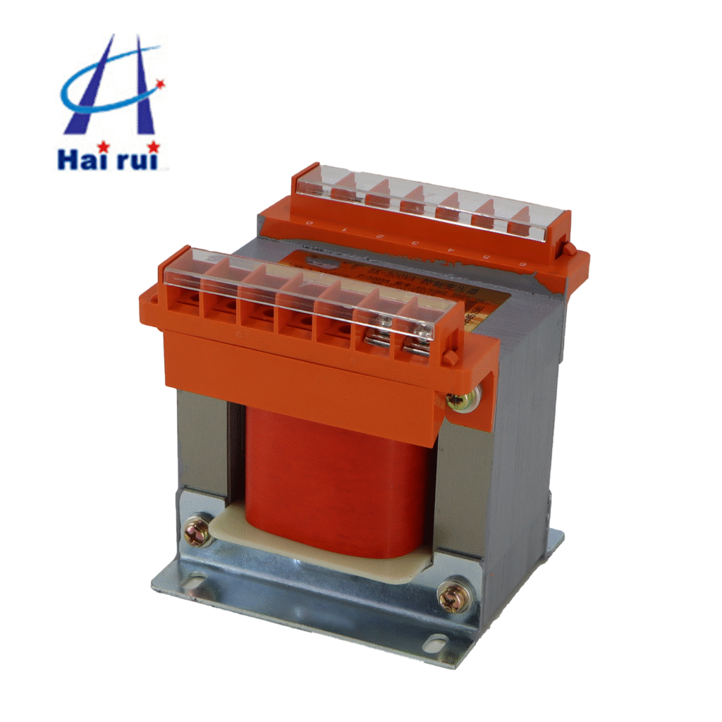
Mounting and grounding
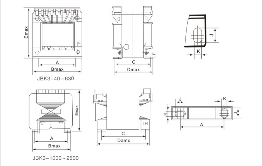
Most JBK3 transformers use shell‑type laminated cores and are mounted with through‑bolt holes on the base.
Follow these guidelines:
Secure the transformer to the panel using all recommended mounting holes. A loose transformer can vibrate, leading to loose connections and partial phase faults.
Connect the transformer frame to the cabinet grounding bar using a separate copper wire (minimum 4 mm² or per local code).
Do not use the transformer casing as the main grounding path; use a dedicated grounding conductor.
Proper grounding and mounting reduce the risk of arcing and insulation stress, which can indirectly increase the chance of overload‑related failure.
Cable management and labeling
Use separate terminal blocks for each secondary voltage (e.g., one block for 24 V, one for 220 V).
Mark each terminal with voltage and purpose (e.g., “24 V AC – RLY‑1, RLY‑2”).
Document the total VA per tap on the panel layout drawing and keep it in the control cabinet.
When maintenance staff later add a new device, they can see at a glance whether the 24 V rail is already close to its VA limit, and decide whether to add a dedicated JBK3‑250 instead of overloading the existing one.
Protection and monitoring—how to catch overload before it kills the transformer
Just like a wise transformer salesman, a good JBK3 configuration doesn’t count on people remembering the VA limit. Here are practical ways to protect your low‑voltage machine control transformer.
Primary‑side fuses or breakers
Choose fuses or breakers that match the transformer’s rated current and your local standards:
Primary overcurrent protection typically ≤ 125% of full‑load primary current.
For example, a JBK3‑250 at 380 V has a full‑load current of about 0.66 A. A 1 A or 1.6 A fuse is generally acceptable (check local rules).
Always document the fuse rating and part number on the cabinet label plate. Staff can then easily replace it with the correct type instead of “borrowing” a larger one from another machine.
Thermal protection (if available)
Some JBK3 series machine tool control transformers have built‑in thermal protection (e.g., thermal cut‑out or connection points for an external temperature sensor). If yours does:
Connect the thermal switch in series with the control circuit so that the transformer power is cut off when temperature rises too high.
Route the thermal‑protection wire clearly and label it as “THERMAL‑PROT” to avoid being confused with a normal control signal.
If the transformer does not have this built‑in feature, you can consider external thermal protection or monitoring cabinet temperature using a separate sensor.
Visual and operational checks
Once the JBK3 is wired and running, perform periodic checks:
Touch test: The transformer should feel warm but not hot enough to scald.
Smell test: Any burning or “hot insulation” smell is a red flag.
Voltage check: Measure secondary voltages under load; if they drop significantly below rated values, the transformer may be overloaded or the wiring is undersized.
If you are a procurement manager responsible for multiple machines, ask your maintenance team to keep a log of transformer temperature and load for high‑risk machines. This data helps you plan preventive replacements and justify investment in larger JBK3 models.
How to avoid common overloading mistakes in real projects
Let’s face it: nobody buys a JBK3 control transformer to make it fail. Yet, certain patterns pop up again and again in the field. Here are some real‑world mistakes and how to avoid them.
“We’ll just add a few more relays”
One of the most common causes of JBK3 overload is incremental additions. Initially, a JBK3‑100 might be fine for a simple lathe, but over time:
Extra relays are added on the same 24 V tap.
A small PLC or HMI power supply is “piggybacked” onto an existing 24 V rail.
Result: the 24 V winding is suddenly carrying 120 VA, even though the transformer is only rated for 100 VA.
Solution:
Define a maximum VA budget per JBK3 model and keep it in the panel documentation.
When new loads are added, recalculate the total VA and upgrade the transformer if needed.
If you are a JBK3 control transformer Manufacturer or OEM, you can also standardize on JBK3‑250 or JBK3‑400 for most machines, which reduces the risk of overload during customization.
Sharing the same transformer for control and lighting
Another classic mistake is using the same JBK3 transformer for both control circuits and workshop lighting:
A single JBK3‑160 feeding 24 V PLC, 220 V contactors, and 220 V work lights.
Control loads are intermittent, but lighting loads are often continuous. This can push the transformer into overload because:
Lighting loads are resistive and have no “off” phase.
Voltage drop and heat accumulation build up over time.
Solution:
Use separate transformers for control power and lighting, or
Use a larger JBK3 frame (e.g., JBK3‑400 or JBK3‑630) if both must share the same unit.
This is a good argument for B‑to‑B buyers who want to reduce warranty claims and service calls.
Ignoring voltage taps and wrong primary selection
Some engineers choose the wrong primary voltage tap on the JBK3 transformer, for example:
Using a 440 V input when the supply is actually 380 V, which can cause the secondary voltage to rise and increase the effective VA drawn by some loads.
Always:
Match the primary tap to the actual supply voltage.
Verify the secondary voltage after installation under load.
If your factory has multiple voltage standards (e.g., 380 V, 400 V, 415 V), consider multi‑tap JBK3 models so you can use the same transformer design across different regions.
If you’re choosing JBK3 industrial low‑voltage machine control transformers for a batch of machines, it pays to get the right model and wiring done early—less downtime, fewer emergency replacement orders, and happier maintenance teams.
If you want, you can send me your project specs I’ll help you pick the right industrial JBK3 industrial low‑voltage machine control transformer model and quantity.
How do I know if my JBK3 industrial low‑voltage machine control transformer is overloaded?
If the transformer is very hot to the touch, there is a burning smell, or the secondary voltage drops significantly under load, it may be overloaded. Check the total VA of all connected devices and compare it to the JBK3 model’s rated VA.
Can I connect more than one JBK3 to the same line to share the load?
Yes, you can install multiple JBK3 control transformers on the same supply line, but each must be sized and protected individually. This is common when you want separate 24 V and 220 V control rails, or when you need to avoid overloading a single transformer.
What happens if I slightly exceed the rated VA of a JBK3 machine tool control transformer?
A small, short‑term overload may not immediately fail the unit, but continuous overloading shortens insulation life, increases temperature, and raises the risk of failure over time. For industrial use, staying within rated VA plus a safety margin is the best practice.
Should I use a JBK3‑250 or JBK3‑400 for a mid‑size PLC‑based machine?
If your total control load (PLC, relays, contactors, lamps) with 20–30% margin is under 250 VA, a JBK3‑250 is usually enough. If the load is close to 250 VA or likely to grow, choose a JBK3‑400 to avoid future overloading during upgrades.
Can I use a JBK3 transformer for both control circuits and small workshop lighting?
You can, but it’s safer to keep control power and lighting on separate circuits or use a larger JBK3 frame (like JBK3‑400 or JBK3‑630). Mixing continuous lighting loads with control loads can push the transformer into overload.
How do I protect a JBK3 transformer from overload?
Use correctly sized primary fuses or breakers (around 125% of full‑load current), keep total VA below rated capacity, ensure good ventilation, and avoid adding extra devices without checking the VA budget. If available, connect built‑in thermal protection into the control circuit.
Why does my JBK3 control transformer get hotter than expected?
Possible reasons include overloading, poor ventilation, wrong VA sizing, or operation at a higher input voltage than the selected tap. Check the load, mounting clearance, and wiring to see where the heat is coming from.
Can I order a custom JBK3 series machine tool control transformer for special voltages?
Many manufacturers offer JBK3‑series transformers with custom primary and secondary voltages or multi‑tap configurations for OEMs and panel builders. If you need a specific voltage split for your machines, discussing a customized JBK3 model with your supplier can help avoid future overloading issues.
When you wire a 480V to 120V control transformer Wiring correctly, you get stable low‑voltage power for control circuits, PLC I/O, contactor coils, and panel auxiliaries—wired incorrectly, you get nuisance trips, overheated transformers, or even damaged equipment. This guide walks engineers, panel builders, and purchasing teams through how the wiring diagram works, typical 480V primary […]
A JBK3 Control Transformer is a device that steps down voltage from a higher level to a lower, safer level for use in control circuits. These transformers are commonly used in industrial automation, HVAC systems, and machinery. They help protect sensitive equipment by providing stable, low-voltage power for relays, contactors, and other control devices. What […]
In today’s competitive manufacturing and automation world, Industrial Control Transformer power stability is everything. When you’re running machines 24/7, a single voltage drop or short circuit event can cause unwanted downtime—and in industries like processing or automation, downtime equals lost revenue. That’s where an industrial control transformer steps in. Let’s break down why this small but crucial component deserves […]
We use cookies to enhance your browsing experience, serve personalised ads or content, and analyse our traffic. By clicking "Accept All", you consent to our use of cookies.