When you wire a 480V to 120V control transformer Wiring correctly, you get stable low‑voltage power for control circuits, PLC I/O, contactor coils, and panel auxiliaries—wired incorrectly, you get nuisance trips, overheated transformers, or even damaged equipment. This guide walks engineers, panel builders, and purchasing teams through how the wiring diagram works, typical 480V primary / 120V secondary configurations, and what to check before you sign off a control panel or place a bulk order.
If you are sourcing large volumes or need custom primary/secondary combinations, you can always send your single‑line diagrams and load list to your transformer supplier to get a tailored wiring proposal and quotation.
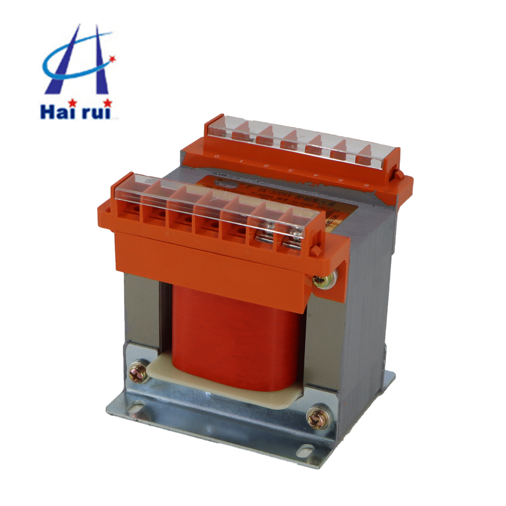
What a 480V to 120V Control Transformer Actually Does
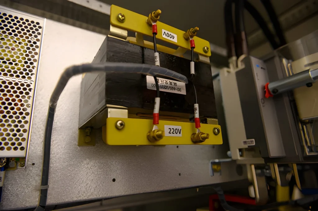
A 480V to 120V control transformer Wiring is a single‑phase step‑down transformer that takes a high‑voltage line (typically from a 480V distribution or motor control center) and converts it to 120V for control circuits, HMI, lighting, or small single‑phase loads. In many industrial systems this is the safest and most economical way to power control logic without running separate 120V feeders across the plant.
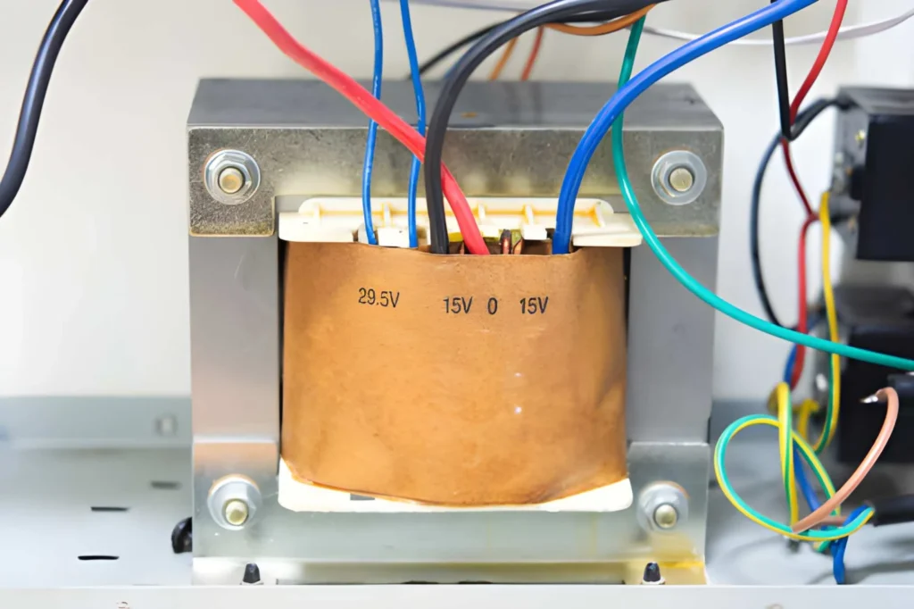
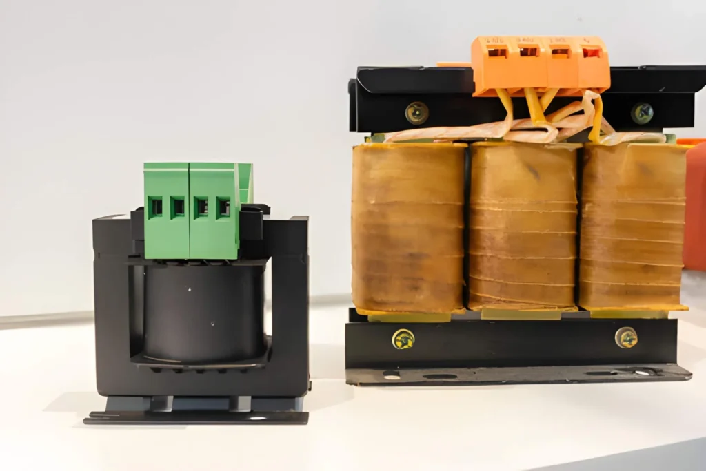
In most designs, the primary winding is rated 240/480V or 240/480/600V, and the secondary winding provides 120V or 120/240V, sometimes with multiple taps for 110/115/120V control voltages. That is why the wiring diagram on the nameplate often shows several options, not just a single fixed connection.
Typical nameplate options for 480V ➝ 120V control transformers
Aspect
Typical values (example products)
Why it matters
Primary voltage range
240/480V, sometimes 240/480/600V
Allows use on different plant distribution systems.
Secondary voltage options
110/115/120V or 120/240V dual secondary
Fits control coils, relays, small loads with different nominal voltages.
Frequency
50/60 Hz, single‑phase
Supports export machinery and global installations.
VA rating
50 VA, 100 VA, 250 VA, 1000 VA etc.
Must match total load of contactors, PLCs, lamps, etc.
Construction type
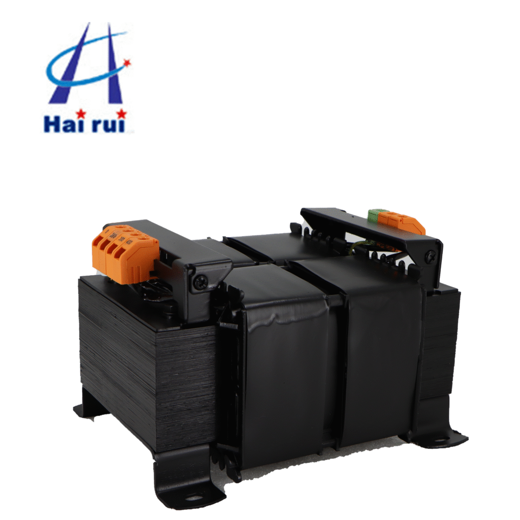
Open core‑coil, epoxy resin encapsulated, machine tool type
Impacts mounting, environment, and heat dissipation.
When you plan your 480V to 120V Control Transformer Wiring, you always start from the nameplate diagram because each manufacturer uses slightly different terminal markings and tap options, even if the function looks similar.
How to Read a 480V to 120V Control Transformer Wiring Diagram
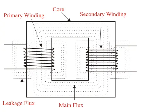
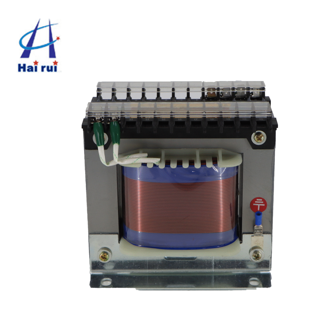
Many B2B buyers and even some engineers find the first transformer diagram confusing because it shows multiple windings, series/parallel options, and several terminal labels such as H1, H2, H3, H4 on the primary and X1, X2, X3, X4 on the secondary. Yet once you understand the pattern, most 480V to 120V control transformer wiring diagrams follow the same logic.
At a high level, the primary side typically has two identical coils that can be wired in series for 480V or in parallel for 240V, while the secondary often has two coils that can be wired for 120V only or 120/240V service. This is why the same physical transformer can be used in multiple configurations, just by changing links or jumpers.
Common terminal conventions on wiring diagrams
Side
Terminals
Typical role in 480V ➝ 120V wiring
Notes
Primary
H1, H4
480V line inputs when coils are in series
Connect your 480V L1 and L2 (or L and N) here according to the diagram.
Primary
H2, H3
Series/parallel jumpers between primary coils
Often linked together for 480V series connection.
Secondary
X1, X4
Outer ends of secondary windings
For 240V between X1 and X4 in many dual‑voltage designs.
Secondary
X2, X3
Inner ends / center‑tap points
Linked for 120/240V systems; one point may be neutral.
Before wiring, engineers should always confirm:
The primary voltage that will actually be applied (480V, 460V, 440V, or 240V).
Whether a neutral is required on the primary side (for some grounded systems).
Which secondary voltage and configuration is required (120V only, or 120/240V split).
A quick review of the wiring diagram with your panel shop or OEM supplier early in the project avoids change orders on the factory floor.
Step‑by‑Step Wiring 480V Primary and 120V Secondary
Now let’s look at how a typical 480V to 120V JBK3 Machine Tool control transformer is wired in practice, based on common single‑phase transformer diagrams and manufacturer instructions. Exact steps will depend on the specific product and local electrical code, but the sequence is similar across brands.
From a functional point of view, wiring a 480V to 120V control transformer involves three tasks: configuring the primary windings for 480V, configuring the secondary windings for 120V, and then connecting grounding and overcurrent protection. If any of those steps are skipped or done incorrectly, the control circuit may see the wrong voltage, or the transformer may run hot.
Example wiring logic for 480V in / 120V out
Step
Primary (480V) wiring example
Secondary (120V) wiring example
1
Bond H2 and H3 together to place two 240V coils in series for 480V.
Decide whether you need 120V only or 120/240V output based on loads.
2
Connect 480V Line 1 (L1) to H1.
For 120V only, link X2 and X4 (neutral) and use X1 and X3 as the 120V hot.
3
Connect 480V Line 2 (L2) to H4.
For 120/240V, link X2 and X3 as neutral/center‑tap and use X1 and X4 for 240V.
4
Install primary fuses or breaker per local code and manufacturer guidance.
Connect load neutral to the chosen neutral terminal, and load hot to the 120V hot terminal(s).
5
Bond transformer core and secondary neutral to ground where required.
Verify correct voltage at terminals before energizing the full control circuit.
In many industrial designs, the secondary neutral is grounded to create a separately derived 120V system, which improves safety and fault clearing, but grounding methods must follow local regulations and the equipment standard. Before energizing connected PLCs or contactor coils, technicians typically test the secondary with a multimeter to confirm 120V under no‑load and then under partial load.
If your project has a mix of control voltages (for example, 24V DC for PLCs and 120V AC for contactors), it is common to combine the 480V to 120V JBK3 Machine Tool control transformers with a subsequent power supply, so proper wiring at each stage is essential for long‑term reliability.
Practical Use Cases and Procurement Considerations
Control transformers with 480V primary and 120V secondary show up in a wide range of B2B applications: from machine tools to HVAC units, from small OEM panels to building lighting systems. For purchasing teams and project engineers, understanding the wiring diagram is part of the buying decision, because it tells you how flexible the unit will be across different projects and markets.
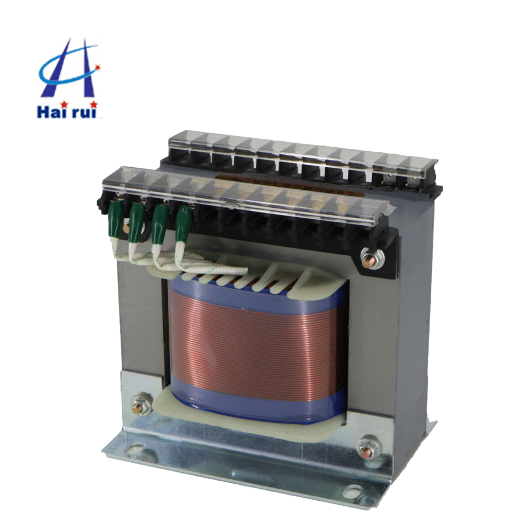
Typical examples include 480V machine tool or industrial control transformers that accept 240/480V on the primary and deliver a 120V control supply, sized from 50 VA for a simple starter up to 1000 VA or more for complex control panels. Some epoxy‑encapsulated versions are designed for harsh environments, with terminals and wiring diagrams optimized for cabinet mounting and straightforward series/parallel configuration.
Key selection factors for B2B buyers
Factor
What to check
Why it matters for 480V ➝ 120V wiring
Primary configurations
240/480 or 240/480/600, with clear H1–H4 markings
Ensures easy series wiring for 480V and flexibility for other voltages.
Secondary options
120V only or 120/240V with X1–X4 terminals
Determines if you can power mixed 120V and 240V loads from one unit.
VA rating and inrush
Total VA of coils, PLCs, lamps, and inrush loads
Avoids undervaluing the transformer and overheating issues.
Standards and approvals
UL, CSA, CE, or regional certifications
Facilitates panel certification and export to other markets.
Mounting and environment
Open, enclosed, or encapsulated, plus IP rating
Affects wiring space, cooling, and durability in dusty or humid areas.
When you are comparing suppliers, request both the datasheet and the wiring diagram, not only the catalog VA rating, so your engineering team can verify that the available connections match your intended 480V to 120V control scheme. If you are planning a long‑term frame agreement, it also makes sense to standardize on one or two wiring styles to simplify panel documentation and technician training.
If you already have a project in mind, feel free to share your line diagram, control loads, and preferred primary voltages with the Control Transformer manufacturer and ask them to recommend the most suitable 480V to 120V Control Transformer Wiring configuration for your application.
If you’re planning new control panels, exports to 50/60 Hz markets, or large‑volume transformer purchases, consider sending your specifications, preferred wiring diagrams, and standards requirements to your supplier so they can propose the most suitable 480V to 120V control transformer solution and offer a competitive quote.
FAQ
How do I wire a transformer for 480V input and 120V output?
In a typical dual‑primary design you connect the two primary coils in series for 480V by linking H2 and H3 together, then bring your 480V lines to H1 and H4 according to the wiring diagram. On the secondary, you usually configure the windings for 120V by tying specific terminals together (for example X2–X4 as neutral and X1–X3 as hot) as shown in the manufacturer’s drawing.
Why are there multiple primary voltages like 240/480V on the same transformer?
Manufacturers often design control transformers with dual primaries so they can be wired in parallel for 240V or in series for 480V, which reduces inventory and supports different plant supply systems. The wiring diagram illustrates how to jumper the H‑terminals for each voltage, making the same device usable in several regions and applications.
Can I get 120/240V from a 480V to 120V control transformer?
Many industrial control transformers have dual secondary windings that can be wired for 120V only or for 120/240V with a center tap, depending on how X1–X4 are linked. However, not every 480V to 120V transformer supports a 240V secondary, so checking the nameplate and wiring diagram is essential before planning mixed‑voltage loads.
What happens if I wire a 480V primary transformer incorrectly?
If the primary coils are wired incorrectly—for example, left in parallel but supplied with 480V—you may over‑flux or overheat the transformer, leading to insulation damage or a failed unit. Incorrect secondary wiring can also result in abnormal voltages on control circuits, causing mis‑operation or premature failure of contactors, relays, and PLC power supplies.
Do I need to ground the secondary neutral on a 480V to 120V control transformer?
In many installations, the 120V secondary is treated as a separately derived system and its neutral point is bonded to ground to improve fault clearing and safety, following electrical codes and standards. The specific grounding scheme should always follow local regulations and the equipment manufacturer’s recommendations for the control panel or machine.
Micron control transformers sit quietly in your control panel, but they decide whether your machinery starts smoothly or fails at the worst possible moment. For OEMs, panel builders, and purchasing managers, choosing the right Micron control transformer is not just a technical decision, it is a reliability and cost decision across the whole life cycle […]
Transformers are everywhere in electrical systems. But not all transformers serve the same purpose. If you work with industrial machines, HVAC equipment, CNC systems, or automation control panels, you’ve likely heard the term control transformer. So what makes a control transformer different from a power transformer? In this article, we’ll explore their differences in function, […]
In most industrial panels, a standard 480V to 120V control transformer is designed to provide a single 120V secondary for control power, not a 120/240V split‑phase system. You can only get 120/240V from it if the secondary is specifically wound and brought out as 120/240V (with a center tap), or if you add an additional […]
We use cookies to enhance your browsing experience, serve personalised ads or content, and analyse our traffic. By clicking "Accept All", you consent to our use of cookies.